time NISSAN TIIDA 2007 Service Repair Manual
[x] Cancel search | Manufacturer: NISSAN, Model Year: 2007, Model line: TIIDA, Model: NISSAN TIIDA 2007Pages: 5883, PDF Size: 78.95 MB
Page 1 of 5883
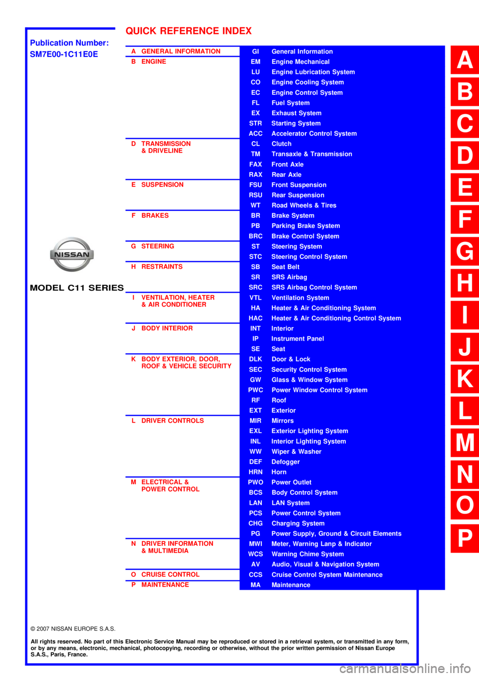
MODEL C11 SERIES
2007 NISSAN EUROPE S.A.S.
All rights reserved. No part of this Electronic Service Manual may be reproduced or stored in a retrieval system, or transmitted in any form,
or by any means, electronic, mechanical, photocopying, recording or otherwise, without the prior written permission of Nissan Europe
S.A.S., Paris, France.
A GENERAL INFORMATION
B ENGINE
D TRANSMISSION& DRIVELINE
E SUSPENSION F BRAKES
G STEERING H RESTRAINTS
I VENTILATION, HEATER & AIR CONDITIONER
J BODY INTERIOR
K BODY EXTERIOR, DOOR, ROOF & VEHICLE SECURITY
L DRIVER CONTROLS
M ELECTRICAL & POWER CONTROL
N DRIVER INFORMATION & MULTIMEDIA
O CRUISE CONTROL P MAINTENANCEGI General Information
EM Engine Mechanical
LU Engine Lubrication System
CO Engine Cooling System
EC Engine Control System
FL Fuel System
EX Exhaust System
STR Starting System
ACC Accelerator Control System
CL Clutch
TM Transaxle & Transmission
FAX Front Axle
RAX Rear Axle
FSU Front Suspension
RSU Rear Suspension
WT Road Wheels & Tires
BR Brake System
PB Parking Brake System
BRC Brake Control System
ST Steering System
STC Steering Control System
SB Seat Belt
SR SRS Airbag
SRC SRS Airbag Control System
VTL Ventilation System
HA Heater & Air Conditioning System
HAC Heater & Air Conditioning Control System
INT Interior
IP Instrument Panel
SE Seat
DLK Door & Lock
SEC Security Control System
GW Glass & Window System
PWC Power Window Control System
RF Roof
EXT Exterior
MIR Mirrors
EXL Exterior Lighting System
INL Interior Lighting System
WW Wiper & Washer
DEF Defogger
HRN Horn
PWO Power Outlet
BCS Body Control System
LAN LAN System
PCS Power Control System
CHG Charging System
PG Power Supply, Ground & Circuit Elements
MWI Meter, Warning Lanp & Indicator
WCS Warning Chime System
AV Audio, Visual & Navigation System
CCS Cruise Control System Maintenance
MA Maintenance
QUICK REFERENCE INDEX
A
B
C
D
E
F
G
H
I
J
K
L
M
N
O
P
M
Publication Number:
SM7E00-1C11E0E
Page 2 of 5883

FOREWORD
This manual contains maintenance and repair procedures for the NISSAN
TIIDA, model C11 series.
In order to assure your safety and the efficient functioning of the vehicle,
this manual should be read thoroughly. It is especially important that the
PRECAUTIONS in the GI section be completely understood before starting
any repair task.
All information in this manual is based on the latest product information
at the time of publication. The right is reserved to make changes in speci-
fications and methods at any time without notice.
IMPORTANT SAFETY NOTICE
The proper performance of service is essential for both the safety of the
technician and the efficient functioning of the vehicle.
The service methods in this Service Manual are described in such a man-
ner that the service may be performed safely and accurately.
Service varies with the procedures used, the skills of the technician and the
tools and parts available. Accordingly, anyone using service procedures,
tools or parts which are not specifically recommended by NISSAN must
first be completely satisfied that neither personal safety nor the vehicle's
safety will be jeopardized by the service method selected.
NISSAN EUROPE S.A.S.
Service Engineering SectionParis, France
Page 6 of 5883

AV
AV-1
DRIVER INFORMATION & MULTIMEDIA
C
D
E
F
G
H
I
J
K
L
MB
SECTION AV
A
O
P
CONTENTS
AUDIO, VISUAL & NAVIGATION SYSTEM
AUDIO WITHOUT NAVIGATION
BASIC INSPECTION ....................................
5
DIAGNOSIS AND REPAIR WORKFLOW ..........5
Work Flow .................................................................5
FUNCTION DIAGNOSIS ...............................6
AUDIO SYSTEM ..................................................6
System Diagram ........................................................6
System Description ...................................................6
Component Parts Location ........................................8
Component Description .............................................8
COMPONENT DIAGNOSIS ..........................9
POWER SUPPLY AND GROUND CIRCUIT .......9
AV CONTROL UNIT ....................................................9
AV CONTROL UNIT : Diagnosis Procedure .............9
MICROPHONE ............................................................9
MICROPHONE : Diagnosis Procedure .....................9
STEERING SWITCH ..........................................11
Description ..............................................................11
Diagnosis Procedure ...............................................11
MICROPHONE SIGNAL CIRCUIT .....................13
Description ..............................................................13
Diagnosis Procedure ...............................................13
ECU DIAGNOSIS .........................................15
AV CONTROL UNIT ...........................................15
Reference Value .....................................................15
Wiring Diagram .......................................................17
SYMPTOM DIAGNOSIS ..............................19
MULTI AV SYSTEM SYMPTOMS ......................19
Symptom Table .......................................................19
NORMAL OPERATING CONDITION ...............20
Description ...............................................................20
PRECAUTION ..............................................21
PRECAUTIONS .................................................21
Precaution for Supplemental Restraint System
(SRS) "AIR BAG" and "SEAT BELT PRE-TEN-
SIONER" .................................................................
21
PREPARATION ...........................................22
PREPARATION .................................................22
Commercial Service Tool ........................................22
ON-VEHICLE REPAIR .................................23
AUDIO UNIT ......................................................23
Removal and Installation .........................................23
TWEETER .........................................................24
Removal and Installation .........................................24
FRONT DOOR SPEAKER ................................25
Removal and Installation .........................................25
REAR DOOR SPEAKER ..................................26
Removal and Installation .........................................26
STEERING SWITCH .........................................27
Removal and Installation .........................................27
AUDIO ANTENNA .............................................28
Location of Antenna .................................................28
Removal and Installation of Roof Antenna ..............28
AUDIO WITH NAVIGATION
BASIC INSPECTION ...................................
30
DIAGNOSIS AND REPAIR WORKFLOW ........30
Work Flow ................................................................30
FUNCTION DIAGNOSIS ..............................32
Page 12 of 5883
![NISSAN TIIDA 2007 Service Repair Manual AV
AUDIO SYSTEM
AV-7
< FUNCTION DIAGNOSIS >[AUDIO WITHOUT NAVIGATION]
C
D
E
F
G
H
I
J
K
L
MB A
O
P Description
The link with the NATS IMMU implies that the AV control unit can basically only be operat](/img/5/57395/w960_57395-11.png "NISSAN TIIDA 2007 Service Repair Manual AV
AUDIO SYSTEM
AV-7
< FUNCTION DIAGNOSIS >[AUDIO WITHOUT NAVIGATION]
C
D
E
F
G
H
I
J
K
L
MB A
O
P Description
The link with the NATS IMMU implies that the AV control unit can basically only be operat")
AV
AUDIO SYSTEM
AV-7
< FUNCTION DIAGNOSIS >[AUDIO WITHOUT NAVIGATION]
C
D
E
F
G
H
I
J
K
L
MB A
O
P Description
The link with the NATS IMMU implies that the AV control unit can basically only be operated if connected to the
matching NATS IMMU to which the AV control unit was initially fitted on the production line.
Since radio operation is impossible after the link with the NATS is disrupted, theft of the AV control unit is basi-
cally useless since special equipment is required to reset the AV control unit.
Initialization Process for AV control units That Are Linked to the NATS IMMU
New AV control units will be delivered to the factories in the “NEW” state, i.e. ready to be linked with the vehi-
cle's NATS. When the AV control unit in “NEW” state is first switched on at the factory, it will start up communi-
cation with the vehicle's immobilizer control unit (IMMU) and send a code (the “AV control unit Code”) to the
IMMU. The IMMU will then store this code, which is unique to each AV control unit, in its (permanent) memory.
Upon receipt of the code by the IMMU, the NATS will confirm correct receipt of the AV control unit code to the
AV control unit. Hereafter, the AV control unit will operate as normal.
During the initialization process, “NEW” is displayed on the AV control unit display. Normally though, communi-
cation between AV control unit and IMMU takes such a short time (300 ms) that the AV control unit seems to
switch on directly without showing “NEW” on its display.
Normal Operation
Each time the AV control unit is switched on afterwards, the AV control unit code will be verified between the
AV control unit and the NATS before the AV control unit becomes operational. During the code verification pro-
cess, “WAIT” is shown on the AV control unit display. Again, the communication takes such a short time (300
ms) that the AV control unit seems to switch on directly without showing “WAIT” on its display.
When The Radio Is Locked
In case of the AV control unit being linked with the vehicle's NATS (immobilizer system), disconnection of the
link between the AV control unit and the IMMU will cause the AV control unit to switch into the lock
(“SECURE”) mode in which the AV control unit is fully inoperative. Hence, repair of the AV control unit is basi-
cally impossible, unless the AV control unit is reset to the “NEW” state for which special decoding equipment is
required.
Clarion has provided their authorized service representatives with so called “decoder boxes” which can bring
the AV control unit back to the “NEW” state, enabling the AV control unit to be switched on after which repair
can be performed. Subsequently, when the repaired AV control unit is delivered to the final user again, it will
be in the “NEW” state to enable re-linking the AV control unit to the vehicle's immobilizer system. As a result of
the above, repair of the AV control unit can only be done by an authorized Clarion representative (when the
owner of the vehicle requests repair and can show personal identification).
Service Procedure
Item Service procedure Description
Battery disconnection No additional action required. –
Radio needs repair Repair needs to be done by authorized rep-
resentative of radio manufacturer since ra-
dio cannot be operated unless it is reset to
NEW state, using special decoding equip-
ment.–
Replacement of radio by new part No additional action required. Radio is delivered in “NEW” state.
Transferring radio to another vehicle/re-
placement of radio by an old partRadio needs to be reset to NEW state by
authorized representative of radio manu-
facturer.–
Replacement of IMMU Radio needs to be reset to NEW state by
authorized representative of Clarion.After switching on the radio, it will display
“SECURE” after 1 minute.
No communication from IMMU to radio 1. Check NATS system if NATS is mal-
functioning.
2. Reset radio to “NEW” state by autho-
rized representative of Clarion after
NATS is repaired.The radio will display “SECURE” after 1
minute after switching on the radio. Further
use of radio is impossible until communica-
tion is established again, or after radio is re-
set by authorized representative of Clarion.
When initialized between ECM and IMMU. Radio needs to be reset to “NEW” status by
authorized representative of Clarion.It will display “SECURE” after 1 minute after
switching on the radio.
Page 25 of 5883
![NISSAN TIIDA 2007 Service Repair Manual AV-20
< SYMPTOM DIAGNOSIS >[AUDIO WITHOUT NAVIGATION]
NORMAL OPERATING CONDITION
NORMAL OPERATING CONDITION
DescriptionINFOID:0000000001728625
RELATED TO AUDIO
The majority of the audio malfunctions](/img/5/57395/w960_57395-24.png "NISSAN TIIDA 2007 Service Repair Manual AV-20
< SYMPTOM DIAGNOSIS >[AUDIO WITHOUT NAVIGATION]
NORMAL OPERATING CONDITION
NORMAL OPERATING CONDITION
DescriptionINFOID:0000000001728625
RELATED TO AUDIO
The majority of the audio malfunctions")
AV-20
< SYMPTOM DIAGNOSIS >[AUDIO WITHOUT NAVIGATION]
NORMAL OPERATING CONDITION
NORMAL OPERATING CONDITION
DescriptionINFOID:0000000001728625
RELATED TO AUDIO
The majority of the audio malfunctions are the result of outside causes (bad CD, electromagnetic interfer-
ence, etc.). Check the symptoms below to diagnose the malfunction.
The vehicle itself can be a source of noise if noise prevention parts or electrical equipment is malfunctioning.
Check that noise is caused and/or changed by engine speed, ignition switch turned to each position, and
operation of each piece of electrical equipment. Then determine the cause.
NOTE:
CD-R is not guaranteed to play because they can contain compressed audio (MP3, WMA) or could be incor-
rectly mastered by the customer on a computer.
Check that the CDs carry the Compact Disc Logo. If not, the disc is not mastered to the red book Compact
Disc Standard and may not play.
Noise resulting from variations in field strength, such as fading noise and multi-path noise, or external noise from trains and other
sources, is not a malfunction.
NOTE:
Fading noise: This noise occurs because of variations in the field strength in a narrow range due to mountains or buildings blocking
the signal.
Multi-path noise: This noise results from a time difference between the broadcast waves directly from the station arriving at the
antenna and the waves reflected by mountains or buildings.
RELATED TO TELEPHONE
Symptoms Cause and Counter measure
Cannot playCheck that the CD was inserted correctly.
Check that the CD is scratched or dirty.
Check that there is condensation inside the player, and if there is, wait until the condensation is
gone (about 1 hour) before using the player.
The player will play correctly after it returns to the normal temperature if there is a temperature
increase error.
Only the music CD files (CD-DA data) will be played if there is a mixture of music CD files (CD-
DA data) and MP3/WMA files on a CD.
Files with extensions other than “.MP3”, “.WMA”, “.mp3”, or “.wma” cannot be played.
Check that the finalization process, such as session close and disc close, is done for the disc.
Check that the CD is protected by copyright.
Poor sound quality Check that the CD is scratched or dirty.
It takes a relatively long time before
the music starts playing.If there are many folder or file levels on the MP3/WMA CD, or if it is a multisession disc, some
time may be required before the music starts playing.
The songs do not play back in the
desired order.The playback order is the order in which the files were written by the software, so the files might
not play in the desired order.
Symptom Possible cause Possible solution
The system does not recognize the
command.
The system recognizes the com-
mand incorrectly.The interior of the vehicle is too noisy.Close the windows or have other occupants
be quiet.
The volume of the voice is too low. Speak louder.
Pronunciation is unclear. Speak clearly.
Voice recognition mode is not yet ready to speak.Push the release “ ” on the steering
switch, and speak a command after the
tone sounds.
5 seconds or more have passed after pushed and
released “ ” on the steering switch.Make sure to speak a command within
5seconds after push and release “ ” on
the steering switch.
Page 41 of 5883
![NISSAN TIIDA 2007 Service Repair Manual AV-36
< FUNCTION DIAGNOSIS >[AUDIO WITH NAVIGATION]
NAVIGATION SYSTEM
More accurate traveling direction is detected because priorities are set for the signals from these two
devices according to the s](/img/5/57395/w960_57395-40.png "NISSAN TIIDA 2007 Service Repair Manual AV-36
< FUNCTION DIAGNOSIS >[AUDIO WITH NAVIGATION]
NAVIGATION SYSTEM
More accurate traveling direction is detected because priorities are set for the signals from these two
devices according to the s")
AV-36
< FUNCTION DIAGNOSIS >[AUDIO WITH NAVIGATION]
NAVIGATION SYSTEM
More accurate traveling direction is detected because priorities are set for the signals from these two
devices according to the situation.
Map-Matching
Map-matching compares a current location detected by the method
in the “Location Detection Principle” with a road map data from Map
DVD-ROM stored in DVD-ROM drive.
NOTE:
The road map data is based on data stored in the map DVD-ROM.
The vehicle position may not be corrected under the following circumstances and after driving for a certain
time when GPS information is difficult to receive. In this case, the vehicle mark on the display must be cor-
rected manually.
In map-matching, alternative routes to reach the destination will be
shown and prioritized, after the road on which the vehicle is cur-
rently driven has been judged and the vehicle mark has been repo-
sitioned.
Alternative routes will be shown in different order of priority, and
the incorrect road can be avoided if there is an error in distance
and/or direction.
They are of the same priority if two roads are running in parallel.
Therefore, the vehicle mark may appear on either of them alter-
nately, depending on maneuvering of the steering wheel and con-
figuration of the road.
Map-matching does not function correctly when a road on which
the vehicle is driving is new and not recorded in the map DVD-
ROM, or when road pattern stored in the map data and the actual
road pattern are different due to repair.
The map-matching function may find another road and position the
vehicle mark on it when driving on a road not present in the map.
Then, the vehicle mark may change to it when the correct road is
detected.
Effective range for comparing the vehicle position and travel direc-
tion calculated by the distance and direction with the road data
read from the map DVD-ROM is limited. Therefore, correction by
map-matching is not possible when there is an excessive gap
between current vehicle position and the position on the map.
GPS (Global Positioning System)
Type Advantage Disadvantage
Gyroscope
(angular velocity sensor)Can detect the vehicle's turning angle quite
accurately.Direction errors may accumulate when vehicle is
driven for long distances without stopping.
GPS antenna
(GPS information)Can detect the vehicle's travel direction
(North/South/East/West).Correct direction cannot be detected when vehicle
speed is low.
SEL685V
SEL686V
SKIA0613E
Page 42 of 5883
![NISSAN TIIDA 2007 Service Repair Manual AV
NAVIGATION SYSTEM
AV-37
< FUNCTION DIAGNOSIS >[AUDIO WITH NAVIGATION]
C
D
E
F
G
H
I
J
K
L
MB A
O
P
GPS (Global Positioning System) was developed for and is con-
trolled by the US Department of Defe](/img/5/57395/w960_57395-41.png "NISSAN TIIDA 2007 Service Repair Manual AV
NAVIGATION SYSTEM
AV-37
< FUNCTION DIAGNOSIS >[AUDIO WITH NAVIGATION]
C
D
E
F
G
H
I
J
K
L
MB A
O
P
GPS (Global Positioning System) was developed for and is con-
trolled by the US Department of Defe")
AV
NAVIGATION SYSTEM
AV-37
< FUNCTION DIAGNOSIS >[AUDIO WITH NAVIGATION]
C
D
E
F
G
H
I
J
K
L
MB A
O
P
GPS (Global Positioning System) was developed for and is con-
trolled by the US Department of Defense. The system utilizes GPS
satellites (NAVSTAR), sending out radio waves while flying on an
orbit around the earth at an altitude of approximately 21,000 km
(13,100miles).
The GPS receiver calculates the vehicle's position in three dimen-
sions (latitude/longitude/altitude) according to the time lag of the
radio waves received from four or more GPS satellites (three-dimen-
sional positioning). The GPS receiver calculates the vehicle's posi-
tion in two dimensions (latitude/longitude), utilizing the altitude data
calculated previously with radio waves from four or more GPS satel-
lites (two-dimensional positioning) if radio waves were received only
from three GPS satellites.
Position correction by GPS is not available while the vehicle is stopped.
Accuracy of GPS will deteriorate under the following conditions:
In two-dimensional positioning, GPS accuracy will deteriorate when altitude of the vehicle position changes.
The accuracy can be even lower depending on the arrangement of the GPS satellites utilized for the posi-
tioning.
Position detection is not possible when vehicle is in an area where radio waves from the GPS satellite do not
reach, such as in a tunnel, parking lot in a building, and under an elevated highway. Radio waves from the
GPS satellites may not be received when some object is located over the GPS antenna.
NOTE:
Even a high-precision three dimensional positioning, the detection result has an error about 10 m (30ft).
Because the signals of GPS satellite is controlled by the Tracking and Control Center in the United States,
the accuracy may be degraded lower intentionally or the radio waves may stop.
Traffic Information (RDS-TMC)
NOTE:This system is built-in NAVI control unit.
The traffic information broadcast allows to you to avoid delays due to traffic incidents.
Traffic jams, roadwork, closed roads around your current location, etc. are represented graphically on the map
by icons depicting the nature of the event.
Incidents on the route are automatically brought to your attention when they are approached.
The Traffic Information feature gives you the opportunity to forecast traffic incidents, determine how serious
they are, via the guidance mode, and allows you to detour around traffic incidents.
The navigation system receives traffic information from best available sources and enables the RDS-TMC
(Radio Data System-Traffic Information Channel) to inform and guide you.
The RDS-TMC broadcast is fed by a dedicated FM tuner so that you can still tune your radio station while Traf-
fic Information is being broadcasted.
Component Parts LocationINFOID:0000000001728633
Refer to AV-33, "Component Parts Location".
Component DescriptionINFOID:0000000001728634
SEL526V
Part name Description
NAVI CONTROL UNIT The master unit controls each operation of the Navigation system.
Map data can be read from the Map DVD-ROM by installing Map DVD-ROM.
The RGB signal (map information) is output to the display.
The voice guidance signal is output to the audio unit.
MAP DVD-ROM A collection of Map data
DISPLAY UNITMap image signal is input from NAVI control unit, and it map image indicated on
the display.
AUDIO UNIT Voice guidance signal is input from NAVI control unit, and it is output to front
LH/RH speakers.
Each operation of navigation can be performed.
FRONT DOOR SPEAKER
Voice guidance signal from audio unit is output.
FRONT TWEETER
Page 44 of 5883
![NISSAN TIIDA 2007 Service Repair Manual AV
DIAGNOSIS SYSTEM (NAVI CONTROL UNIT)
AV-39
< FUNCTION DIAGNOSIS >[AUDIO WITH NAVIGATION]
C
D
E
F
G
H
I
J
K
L
MB A
O
P
DIAGNOSIS SYSTEM (NAVI CONTROL UNIT)
Diagnosis DescriptionINFOID:00000000017286](/img/5/57395/w960_57395-43.png "NISSAN TIIDA 2007 Service Repair Manual AV
DIAGNOSIS SYSTEM (NAVI CONTROL UNIT)
AV-39
< FUNCTION DIAGNOSIS >[AUDIO WITH NAVIGATION]
C
D
E
F
G
H
I
J
K
L
MB A
O
P
DIAGNOSIS SYSTEM (NAVI CONTROL UNIT)
Diagnosis DescriptionINFOID:00000000017286")
AV
DIAGNOSIS SYSTEM (NAVI CONTROL UNIT)
AV-39
< FUNCTION DIAGNOSIS >[AUDIO WITH NAVIGATION]
C
D
E
F
G
H
I
J
K
L
MB A
O
P
DIAGNOSIS SYSTEM (NAVI CONTROL UNIT)
Diagnosis DescriptionINFOID:0000000001728643
MULTI AV SYSTEM on board diagnosis function
The NAVI control unit diagnosis function starts up with audio switch operation and the NAVI control unit per-
forms a diagnosis for each unit in the system during the on board diagnosis.
Perform a CONSULT-III diagnosis if the on board diagnosis does not start, e.g., the screen does not display
anything, the multifunction switch does not function. etc.
On board diagnosis
Description
The trouble diagnosis function has a self-diagnosis mode for conducting trouble diagnosis automatically and
a confirmation/adjustment mode for operating manually.
The self-diagnosis mode performs diagnoses on the NAVI control unit, connections between system compo-
nents as well as connections between NAVI control unit and GPS antenna. Then it displays the diagnosis
results on the display.
The confirmation/adjustment mode allows the technician to check, modify or adjust the vehicle signals and
set values, as well as to monitor the system error records and system communication status. The check,
modify or adjust actions generally require human intervention and judgment (the system cannot make judg-
ment automatically).
On board diagnosis item
STARTING PROCEDURE
1. Start the engine.
2. Turn the audio system OFF.
Mode Description
Self Diagnosis NAVI control unit diagnosis
Diagnoses the connections across system components, between
NAVI control unit and GPS antenna.
Confirmation/
AdjustmentDisplay DiagnosisThe following check functions are available: color tone check by color
bar display, light and shade check by gray scale display.
Vehicle SignalsDiagnosis of signals can be performed for vehicle speed, parking
brake, lights, ignition switch, and reverse.
Speaker Test The connection of a speaker can be confirmed by test tone.
NavigationSteering Angle Ad-
justmentA difference can be adjusted between the actual turning angle and the
vehicle mark turning angle.
Speed CalibrationA difference can be adjusted between the current location mark and the
actual location.
Error HistoryThe system malfunction and the frequency when occurred in the past
are displayed. The time and place that the selected malfunction last oc-
curred are displayed when the malfunctioning item is selected.
Vehicle CAN Diagnosis The transmitting/receiving of CAN communication can be monitored.
AV COMM DiagnosisThe communication condition of each unit of Multi AV system can be
monitored.
Handsfree PhoneThe received volume adjustment of hands-free phone, microphone
speaker check, and erase memory can be performed.
Bluetooth The passkey and the device name can be checked and changed.
Delete Unit Connection Log Erase the connection history of unit and error history.
Feature Restriction SettingOperations of navigation system while driving can be restricted by us-
ing this function.
Page 45 of 5883
![NISSAN TIIDA 2007 Service Repair Manual AV-40
< FUNCTION DIAGNOSIS >[AUDIO WITH NAVIGATION]
DIAGNOSIS SYSTEM (NAVI CONTROL UNIT)
3. Turn the volume control dial clockwise or counterclockwise for
40 clicks or more while pushing the “SETTIN](/img/5/57395/w960_57395-44.png "NISSAN TIIDA 2007 Service Repair Manual AV-40
< FUNCTION DIAGNOSIS >[AUDIO WITH NAVIGATION]
DIAGNOSIS SYSTEM (NAVI CONTROL UNIT)
3. Turn the volume control dial clockwise or counterclockwise for
40 clicks or more while pushing the “SETTIN")
AV-40
< FUNCTION DIAGNOSIS >[AUDIO WITH NAVIGATION]
DIAGNOSIS SYSTEM (NAVI CONTROL UNIT)
3. Turn the volume control dial clockwise or counterclockwise for
40 clicks or more while pushing the “SETTING” button. (A short
beep will be heard when the self-diagnosis mode is started.)
Shifting from current screen to previous screen is performed
by pushing “BACK” button.
4. The trouble diagnosis initial screen is displayed, and then the
items of “Self Diagnosis” and “Confirmation / Adjustment” can be
selected.
Self-diagnosis mode
1. Start the self-diagnosis function. Then select “Self Diagnosis”.
- Self-diagnosis subdivision screen is displayed, and the self-
diagnosis mode starts.
- The bar graph visible on the center of the self-diagnosis subdivi-
sion screen indicates progress of the trouble diagnosis.
2. Diagnosis results are displayed after the self-diagnosis is com-
pleted. The unit names and the connection lines are color-coded
according to the diagnostic results.
NOTE:
Only the control unit (NAVI control unit) is displayed in red.
- The screen switch colors are determined according to the following order of priority: red > yellow > gray if
multiple errors occur at the same time for a single unit.
JPNIA0173GB
SKIB3961E
SKIB3657E
Diagnosis results Unit Connection
line
Normal Green Green
Connection malfunction Gray Yellow
DVD drive undiagnosed Gray Green
DVD-ROM and DVD-ROM
drive malfunctionYellow Green
Unit malfunction
NoteRed Green
ALNIA0883GB
Page 49 of 5883
![NISSAN TIIDA 2007 Service Repair Manual AV-44
< FUNCTION DIAGNOSIS >[AUDIO WITH NAVIGATION]
DIAGNOSIS SYSTEM (NAVI CONTROL UNIT)
Select “SPEAKER TEST” to display the Speaker Diagnosis screen.
Press “START and NEXT” to generate a tes](/img/5/57395/w960_57395-48.png "NISSAN TIIDA 2007 Service Repair Manual AV-44
< FUNCTION DIAGNOSIS >[AUDIO WITH NAVIGATION]
DIAGNOSIS SYSTEM (NAVI CONTROL UNIT)
Select “SPEAKER TEST” to display the Speaker Diagnosis screen.
Press “START and NEXT” to generate a tes")
AV-44
< FUNCTION DIAGNOSIS >[AUDIO WITH NAVIGATION]
DIAGNOSIS SYSTEM (NAVI CONTROL UNIT)
Select “SPEAKER TEST” to display the Speaker Diagnosis screen.
Press “START and NEXT” to generate a test tone in a speaker.
Press “Start” to generate a test tone in the next speaker. Press
“Stop” to stop the test tones.
NOTE:
The frequency of test tone emitted from each speaker is as follows.
Navigation
STEERING ANGLE ADJUSTMENT
The steering angle output value detected with the gyroscope is
adjusted.
SPEED CALIBRATION
During normal driving, distance error caused by tire wear and tire
pressure change is automatically adjusted for by the automatic dis-
tance correction function. This function, on the other hand, is for
immediate adjustment, in cases such as driving with tire chain fitted
on tires.
ERROR HISTORY
The diagnostic results of “Self-diagnosis” determine if any malfunction occurred between selecting “Self-diag-
nosis” and displaying “Self-diagnostic Results”.
The trouble diagnosis result will be judged normal if an error occurred before the ignition switch was turned
ON and does not occur again until “Self-diagnosis” is completed. Therefore, errors in the past which cannot be
found by “Self-diagnosis”, must be found by checking the “Error record”.
The error history shows the error occurrence frequency in past. The frequency of occurrence is displayed by 2
types: the count down type and the count up type. Select either type according to the error item.
In “Error History” of models with NAVI, time and place that the selected error last occurred are displayed. Be
careful about the following.
The correct date of occurrence may not be able to be displayed if there is a malfunction with the GPS
antenna circuit board in the NAVI control unit.
Place of the error occurrence is represented by the position of the current location mark at the time an error
occurred. If current location mark has deviated from the correct position, then the place of the error occur-
rence cannot be located correctly.Tweeter : 3 kHz
Front door speaker : 300 Hz
Rear door speaker : 1 kHz
SKIB4686E
SKIB3684E
SKIB3685E