NISSAN TIIDA 2009 Service Repair Manual
TIIDA 2009
NISSAN
NISSAN
https://www.carmanualsonline.info/img/5/57398/w960_57398-0.png
NISSAN TIIDA 2009 Service Repair Manual
Trending: fuse box, Top tether, roof rack, lug pattern, Fuel pump relay, Top tether child restraint, ecu connector
Page 3691 of 4331
LT
N
O P
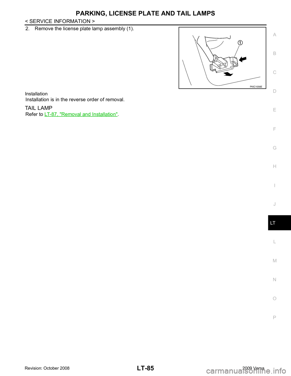
2. Remove the license plate lamp assembly (1).
Installation Installation is in the reverse order of removal.
TAIL LAMP Refer to LT-87, " Removal and Installation " .
Page 3692 of 4331
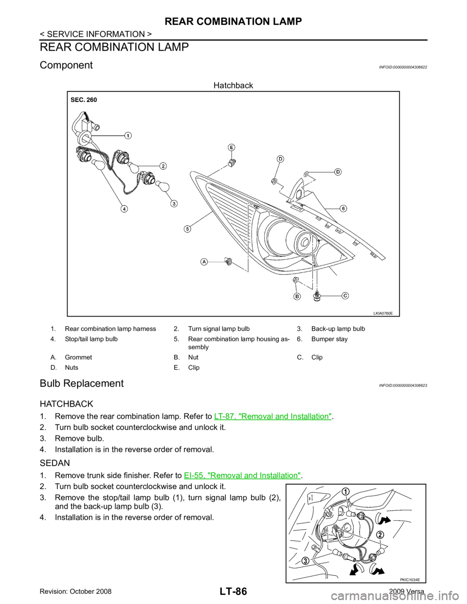
Removal and Installation " .
2. Turn bulb socket counterclockwise and unlock it.
3. Remove bulb.
4. Installation is in the reverse order of removal.
SEDAN
1. Remove trunk side finisher. Refer to EI-55, " Removal and Installation " .
2. Turn bulb socket counterclockwise and unlock it.
3. Remove the stop/tail lamp bulb (1), turn signal lamp bulb (2), and the back-up lamp bulb (3).
4. Installation is in the reverse order of removal.
Page 3693 of 4331
LT
N
O P
Removal and Installation
INFOID:0000000004306624
HATCHBACK
Removal 1. Remove rear combination lamp nuts.
2. Pull the rear combination lamp toward rear of the vehicle and remove from the vehicle.
3. Disconnect rear combination lamp connector, and remove rear combination lamp.
Installation Installation is in the reverse order of removal.
SEDAN
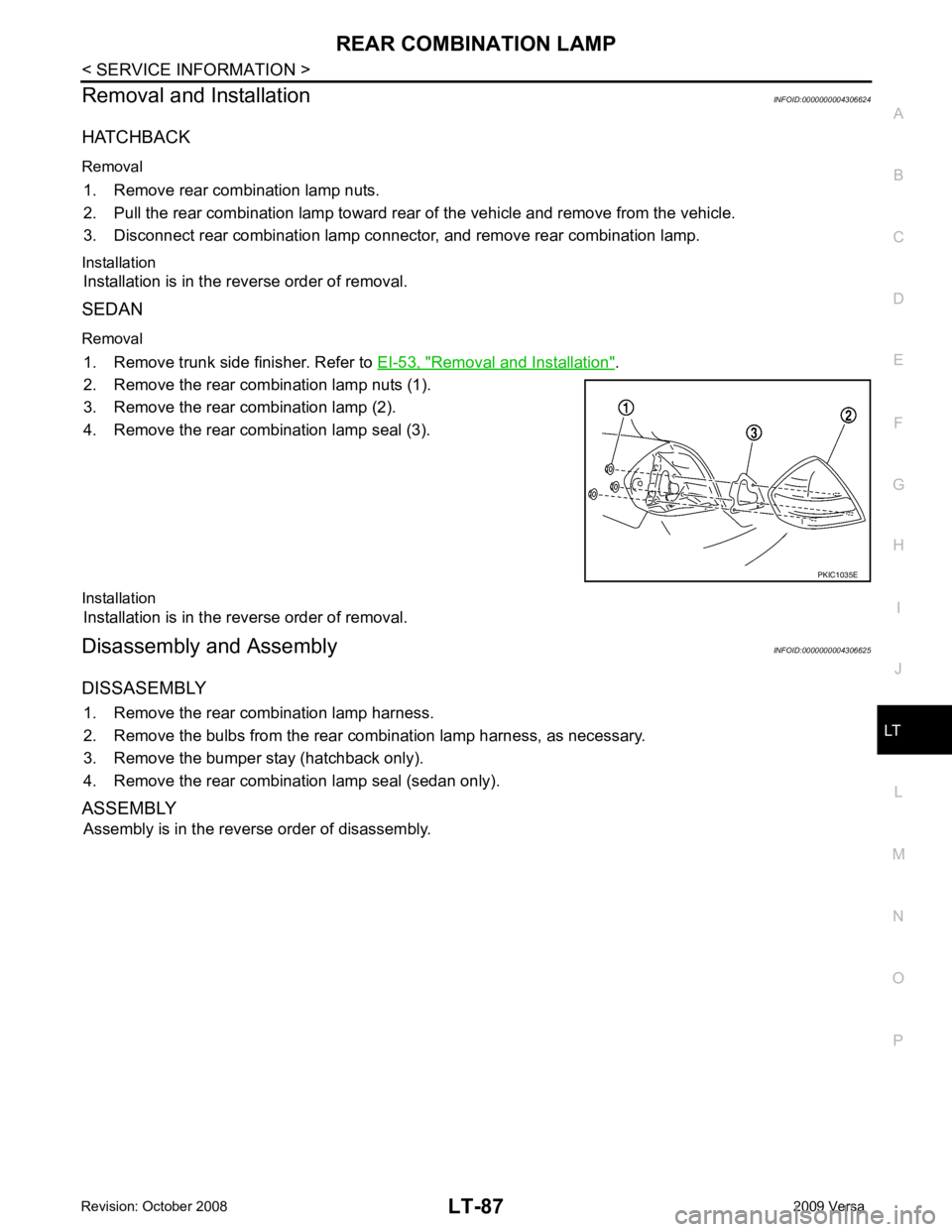
Removal 1. Remove trunk side finisher. Refer to EI-53, " Removal and Installation " .
2. Remove the rear combination lamp nuts (1).
3. Remove the rear combination lamp (2).
4. Remove the rear combination lamp seal (3).
Installation Installation is in the reverse order of removal.
Disassembly and Assembly INFOID:0000000004306625
DISSASEMBLY 1. Remove the rear combination lamp harness.
2. Remove the bulbs from the rear combination lamp harness, as necessary.
3. Remove the bumper stay (hatchback only).
4. Remove the rear combination lamp seal (sedan only).
ASSEMBLY Assembly is in the reverse order of disassembly.
Page 3694 of 4331
Page 3695 of 4331
LT
N
O P
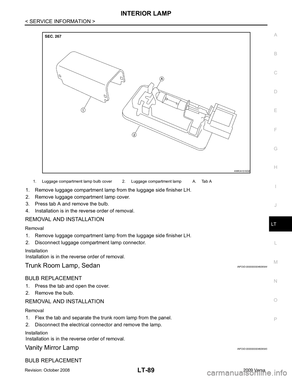
1. Remove luggage compartment lamp from the luggage side finisher LH.
2. Remove luggage compartment lamp cover.
3. Press tab A and remove the bulb.
4. Installation is in the reverse order of removal.
REMOVAL AND INSTALLATION
Removal 1. Remove luggage compartment lamp from the luggage side finisher LH.
2. Disconnect luggage compartment lamp connector.
Installation Installation is in the reverse order of removal.
Trunk Room Lamp, Sedan INFOID:0000000004609544
BULB REPLACEMENT 1. Press the tab and open the cover.
2. Remove the bulb.
REMOVAL AND INSTALLATION
Removal 1. Flex the tab and separate the trunk room lamp from the panel.
2. Disconnect the electrical connector and remove the lamp.
Installation Installation is in the reverse order of removal.
Vanity Mirror Lamp INFOID:0000000004609545
BULB REPLACEMENT 1. Luggage compartment lamp bulb cover 2. Luggage compartment lamp A. Tab A
Page 3696 of 4331
Page 3697 of 4331
LT
N
O P
INTERIOR ROOM LAMP
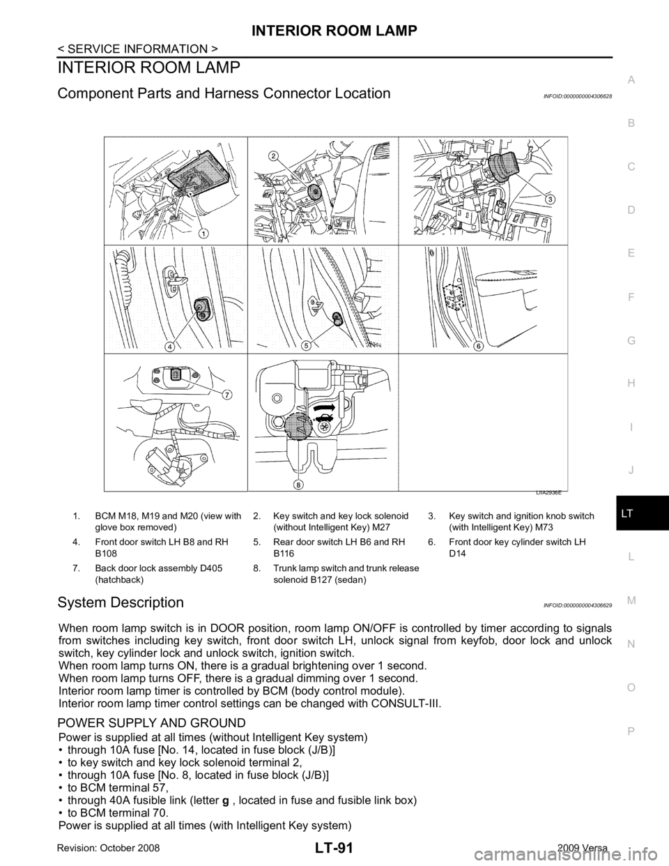
Component Parts and Har ness Connector Location INFOID:0000000004306628
System Description INFOID:0000000004306629
When room lamp switch is in DOOR position, room la mp ON/OFF is controlled by timer according to signals
from switches including key switch, front door switch LH, unlock signal from keyfob, door lock and unlock
switch, key cylinder lock and unlock switch, ignition switch.
When room lamp turns ON, there is a gradual brightening over 1 second.
When room lamp turns OFF, there is a gradual dimming over 1 second.
Interior room lamp timer is controlled by BCM (body control module).
Interior room lamp timer control settings can be changed with CONSULT-III.
POWER SUPPLY AND GROUND Power is supplied at all times (without Intelligent Key system)
• through 10A fuse [No. 14, located in fuse block (J/B)]
• to key switch and key lock solenoid terminal 2,
• through 10A fuse [No. 8, located in fuse block (J/B)]
• to BCM terminal 57,
• through 40A fusible link (letter g , located in fuse and fusible link box)
• to BCM terminal 70.
Power is supplied at all times (with Intelligent Key system) 1. BCM M18, M19 and M20 (view with
glove box removed) 2. Key switch and key lock solenoid
(without Intelligent Key) M27 3. Key switch and ignition knob switch
(with Intelligent Key) M73
4. Front door switch LH B8 and RH B108 5. Rear door switch LH B6 and RH
B116 6. Front door key cylinder switch LH
D14
7. Back door lock assembly D405 (hatchback) 8. Trunk lamp switch and trunk release
solenoid B127 (sedan)
Page 3698 of 4331
Page 3699 of 4331

LT
N
O P
• to map lamp terminal 1
Power is supplied
• through BCM terminal 56
• to map lamp terminal 4.
When interior room lamp switch is ON, ground is supplied
• to interior room lamp terminal 1
• through map lamp (with map lamp) terminal 7
• through map lamp (with map lamp) terminal 1
• through grounds M57 and M61.
Power is supplied
• through BCM terminal 56
• through map lamp (with map lamp) terminal 4
• through map lamp (with map lamp) terminal 6
• to room lamp terminal 3.
INTERIOR ROOM LAMP TIMER OPERATION
Without Intelligent Key System When room lamp switch is in DOOR position, and w hen all conditions below are met, BCM performs timer
control (maximum 30 seconds) for room lamp ON/OFF.
In addition, when the interior room lamp turns ON or OFF there is gradual brightening or dimming over 1 sec-
ond.
Power is supplied
• through 10A fuse [No. 14, located in fuse block (J/B)]
• to key switch and key lock solenoid terminal 2.
When the key is removed from ignition key cylinder (key switch OFF), power will not be supplied to BCM termi-
nal 37.
When front door key cylinder switch LH is unlocked, ground is supplied
• to BCM terminal 7
• through front door key cylinder switch LH terminal 3
• through front door key cylinder switch LH terminal 2
• through grounds M57 and M61.
At the time that front door LH is opened, BCM detects that front door LH is unlocked. It determines that interior
room lamp timer operation condition is met, and turns the room lamp ON for 30 seconds.
When key is in ignition key cylinder (key switch ON),
Power is supplied
• through key switch and key lock solenoid terminal 1
• to BCM terminal 37.
When key is removed from key switch and key lock soleno id (key switch OFF), the power supply to BCM ter-
minal 37 is terminated. BCM detects that key has been re moved, determines that interior room lamp timer
conditions are met, and turns the room lamp ON for 30 seconds.
When front door LH opens → closes, and the key is not inserted in the key switch and key lock solenoid (key
switch OFF), voltage at BCM terminal 47 changes between 0V (door open) → 12V (door closed). The BCM
determines that conditions for room lamp operation are met and turns the room lamp ON for 30 seconds.
Interior room lamp timer control is canceled under the following conditions:
• Front door LH is locked (locked by front door key cylinder switch LH, keyfob or door lock/unlock switch).
• Front door LH is opened (front door switch LH).
• Ignition switch ON.
With Intelligent Key System When the room lamp switch is in DOOR position, and when all conditions below are met, BCM performs timer
control (maximum 30 second) for room lamp ON/OFF.
In addition, when interior room lamp turns ON or OFF there is gradual brightening or dimming over 1 second.
Power is supplied
• through 10A fuse (No. 31, located in fuse and fusible link box)
• to key switch and ignition knob switch terminals 2 and 4.
When key is removed from ignition key cylinder (key switch OFF), power will not be supplied to BCM terminal
37.
When the ignition knob switch is released, power wil l not be supplied to Intelligent Key unit terminal 27.
When front door key cylinder switch LH is unlocked, ground is supplied
• to BCM terminal 7
• through front door key cylinder switch LH terminal 3
Page 3700 of 4331
Trending: Airbag module, Master cylinder, battery capacity, fuel consumption, manual radio set, air suspension, OBD port
