NISSAN TIIDA 2009 Service Repair Manual
Manufacturer: NISSAN, Model Year: 2009, Model line: TIIDA, Model: NISSAN TIIDA 2009Pages: 4331, PDF Size: 58.04 MB
Page 3791 of 4331
MA-48< SERVICE INFORMATION >
CHASSIS AND BODY MAINTENANCE
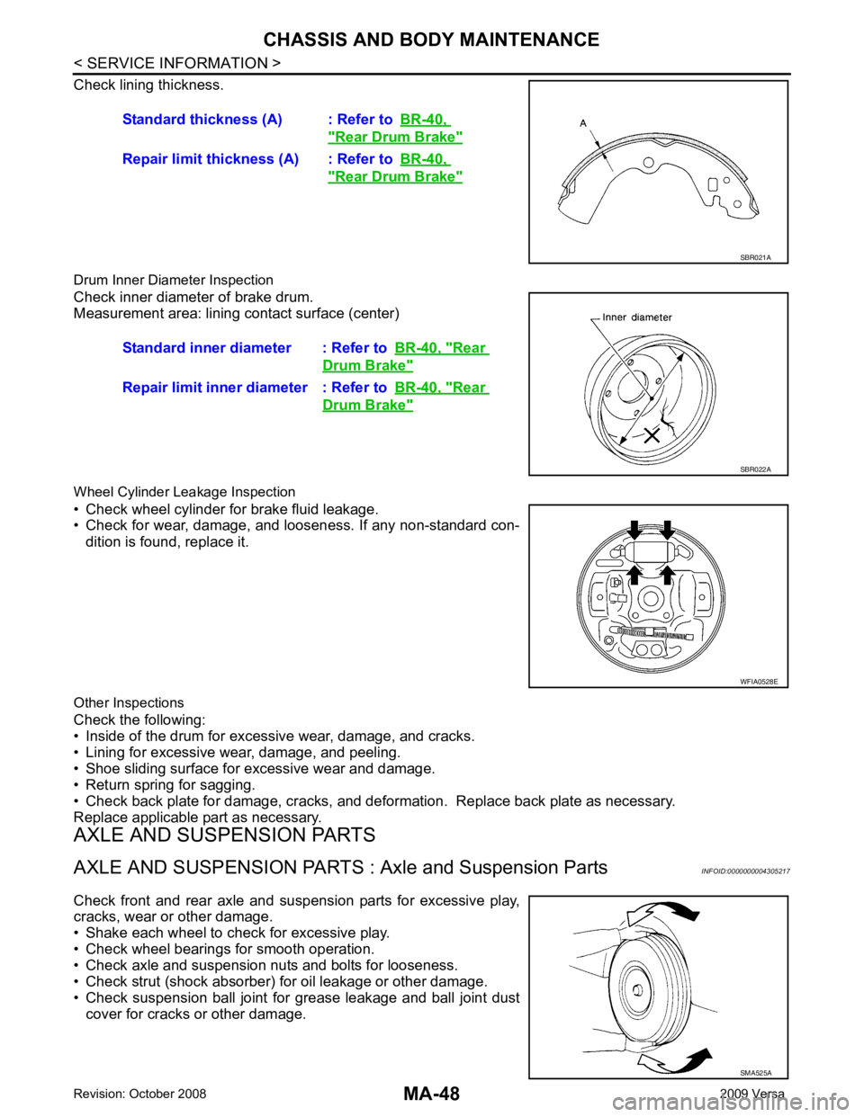
Check lining thickness.
Drum Inner Diameter Inspection
Check inner diameter of brake drum.
Measurement area: lining contact surface (center)
Wheel Cylinder Leakage Inspection
• Check wheel cylinder for brake fluid leakage.
• Check for wear, damage, and looseness. If any non-standard con-
dition is found, replace it.
Other Inspections
Check the following:
• Inside of the drum for excessive wear, damage, and cracks.
• Lining for excessive wear, damage, and peeling.
• Shoe sliding surface for excessive wear and damage.
• Return spring for sagging.
• Check back plate for damage, cracks, and deforma tion. Replace back plate as necessary.
Replace applicable part as necessary.
AXLE AND SUSPENSION PARTS
AXLE AND SUSPENSION PARTS : Axle and Suspension Parts INFOID:0000000004305217
Check front and rear axle and suspension parts for excessive play,
cracks, wear or other damage.
• Shake each wheel to check for excessive play.
• Check wheel bearings for smooth operation.
• Check axle and suspension nuts and bolts for looseness.
• Check strut (shock absorber) for oil leakage or other damage.
• Check suspension ball joint for grease leakage and ball joint dust cover for cracks or other damage. Standard thickness (A) : Refer to
BR-40, " Rear Drum Brake "
Repair limit thickness (A) : Refer to
BR-40, " Rear Drum Brake "
SBR021A
Standard inner diameter : Refer to
BR-40, " Rear
Drum Brake "
Repair limit inner diameter : Refer to
BR-40, " Rear
Drum Brake "
SBR022A
WFIA0528E
SMA525A
Page 3792 of 4331
MA
N
O P
DRIVE SHAFT
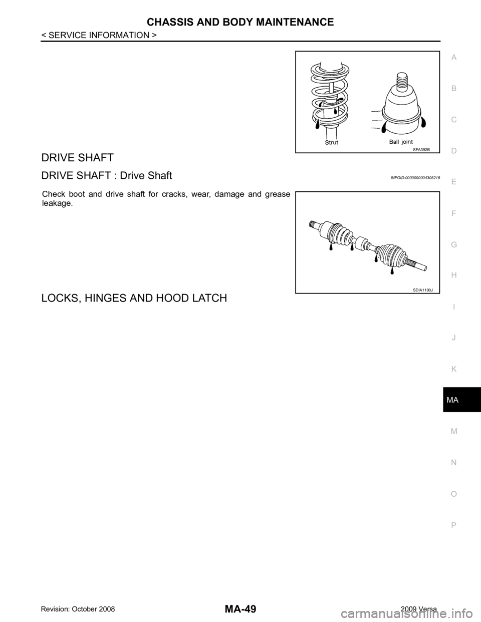
DRIVE SHAFT : Drive Shaft INFOID:0000000004305218
Check boot and drive shaft for cracks, wear, damage and grease
leakage.
LOCKS, HINGES AND HOOD LATCH SDIA1190J
Page 3793 of 4331
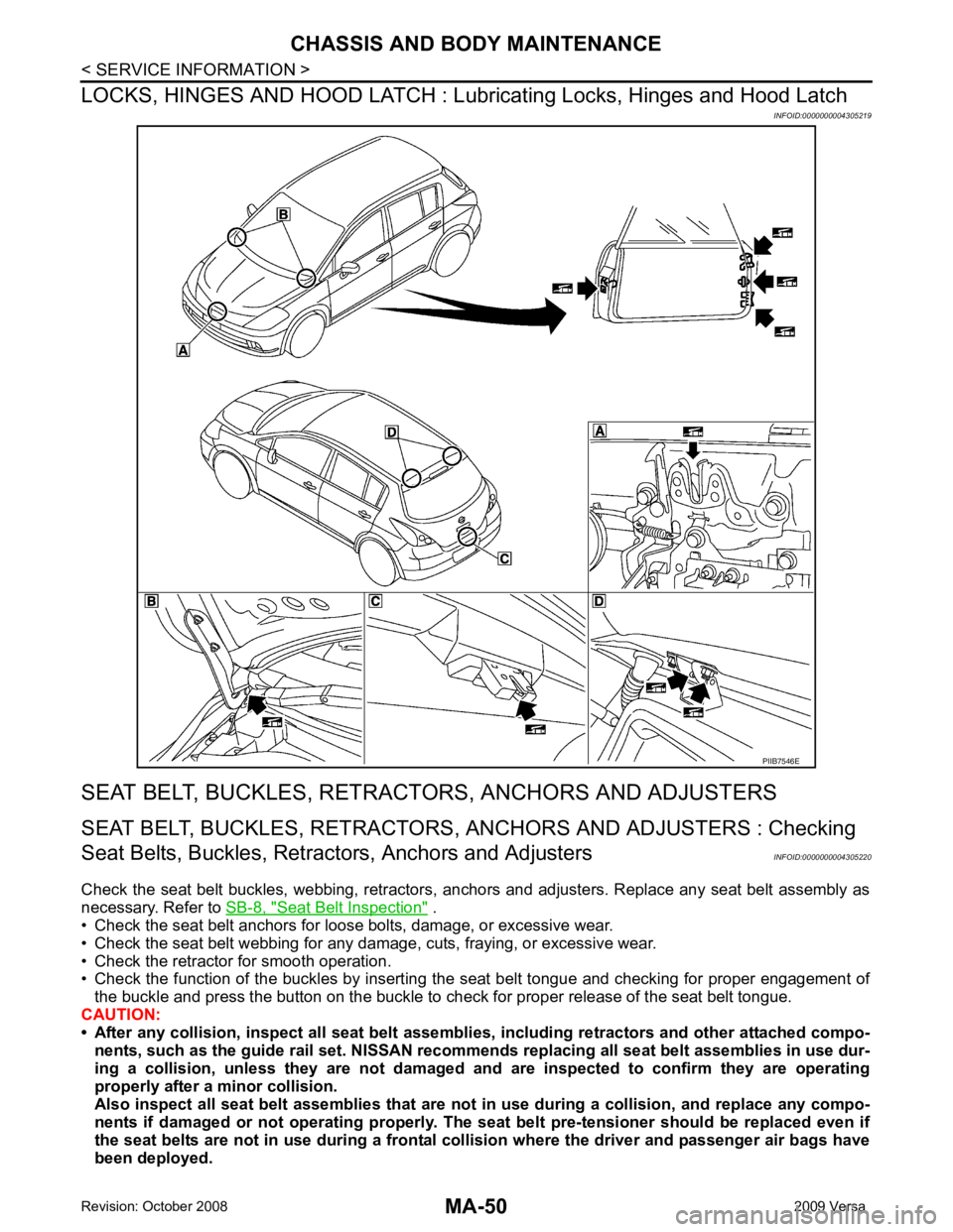
Seat Belt Inspection " .
• Check the seat belt anchors for loose bolts, damage, or excessive wear.
• Check the seat belt webbing for any damage, cuts, fraying, or excessive wear.
• Check the retractor for smooth operation.
• Check the function of the buckles by inserting the seat belt tongue and checking for proper engagement of
the buckle and press the button on the buckle to c heck for proper release of the seat belt tongue.
CAUTION:
• After any collision, inspect all seat belt assembli es, including retractors and other attached compo-
nents, such as the guide rail set. NISSAN recomme nds replacing all seat belt assemblies in use dur-
ing a collision, unless they are not damaged an d are inspected to confirm they are operating
properly after a minor collision.
Also inspect all seat belt assemblies that are not in use during a collision, and replace any compo-
nents if damaged or not operating properly. The seat belt pre-tensioner should be replaced even if
the seat belts are not in use during a frontal coll ision where the driver and passenger air bags have
been deployed.
Page 3794 of 4331

MA
N
O P
• If any component of the seat belt assembly is susp
ected of being damaged or not operating prop-
erly, do not repair the component. Replace the components as an assembly.
• If the seat belt webbing is cut, frayed, or damaged then replace the seat belt assembly.
• Never lubricate the seat belt buckle or tongue.
• When replacing any seat belt assembly alw ays use a Genuine NISSAN seat belt assembly.
Page 3795 of 4331

MT
N
O P
CONTENTS
MANUAL TRANSAXLE
RS5F91R
SERVICE INFORMATION .. ..........................
3
PRECAUTIONS .............................................. .....3
Precaution for Supplemental Restraint System
(SRS) "AIR BAG" and "SEAT BELT PRE-TEN-
SIONER" ............................................................. ......
3
PREPARATION .............................................. .....4
Special Service Tools ........................................ ......4
Commercial Service Tools ................................. ......5
NOISE, VIBRATION AND HARSHNESS
(NVH) TROUBLESHOOTING ........................ .....
7
NVH Troubleshooting Chart ................................ ......7
DESCRIPTION ............................................... .....8
System Diagram .................................................. ......8
System Description ............................................. ......8
M/T OIL ........................................................... ....10
Draining ............................................................... ....10
Refilling ............................................................... ....10
Inspection ............................................................ ....10
SIDE OIL SEAL .............................................. ....11
Removal and Installation .........................................11
POSITION SWITCH ........................................ ....12
Checking ............................................................. ....12
CONTROL LINKAGE ..................................... ....13
Exploded View .................................................... ....13
Removal and Installation .........................................13
Inspection ............................................................ ....14
AIR BREATHER HOSE .................................. ....15
Exploded View .................................................... ....15
Removal and Installation .........................................15
TRANSAXLE ASSEMBLY ............................. ....16
Exploded View .................................................... ....16 Removal and Installation .....................................
....16
Disassembly and Assembly ................................. ....17
INPUT SHAFT AND GEAR ............................... 36
Disassembly and Assembly ................................. ....36
MAINSHAFT AND GEAR ................................. 37
Disassembly and Assembly ................................. ....37
FINAL DRIVE .................................................... 41
Disassembly and Assembly ................................. ....41
SHIFT CONTROL .............................................. 42
Inspection ............................................................ ....42
SERVICE DATA AND SPECIFICATIONS
(SDS) ................................................................. 43
General Specification .......................................... ....43
RS6F94R
SERVICE INFORMATION .. .........................44
PRECAUTIONS ................................................. 44
Precaution for Supplemental Restraint System
(SRS) "AIR BAG" and "SEAT BELT PRE-TEN-
SIONER" ............................................................. ....
44
Precaution for Procedure without Cowl Top Cover ....44
Precaution ........................................................... ....44
PREPARATION ................................................. 45
Special Service Tool ............................................ ....45
Commercial Service Tool .................................... ....47
NOISE, VIBRATION AND HARSHNESS
(NVH) TROUBLESHOOTING ........................... 49
NVH Troubleshooting Chart ................................ ....49
DESCRIPTION .................................................. 50
Cross-Sectional View ...... ........................................50
M/T OIL .............................................................. 52
Changing M/T Oil ................................................. ....52
Checking M/T Oil ................................................. ....52
Page 3796 of 4331

Page 3797 of 4331
MT
N
O P
SERVICE INFORMATION
PRECAUTIONS
Precaution for Supplemental Restraint System (SRS) "AIR BAG" and "SEAT BELT
PRE-TENSIONER" INFOID:0000000004786253
The Supplemental Restraint System such as “A IR BAG” and “SEAT BELT PRE-TENSIONER”, used along
with a front seat belt, helps to reduce the risk or severi ty of injury to the driver and front passenger for certain
types of collision. This system includes seat belt switch inputs and dual stage front air bag modules. The SRS
system uses the seat belt switches to determine the front air bag deployment, and may only deploy one front
air bag, depending on the severity of a collision and w hether the front occupants are belted or unbelted.
Information necessary to service the system safely is included in the SRS and SB section of this Service Man-
ual.
WARNING:
• To avoid rendering the SRS inoper ative, which could increase the risk of personal injury or death in
the event of a collision which would result in air bag inflation, all maintenance must be performed by
an authorized NISSAN/INFINITI dealer.
• Improper maintenance, including in correct removal and installation of the SRS can lead to personal
injury caused by unintentional act ivation of the system. For removal of Spiral Cable and Air Bag
Module, see the SRS section.
• Do not use electrical test equipm ent on any circuit related to the SRS unless instructed to in this
Service Manual. SRS wiring harnesses can be identi fied by yellow and/or orange harnesses or har-
ness connectors.
• When working near the Airbag Diagnosis Sensor Un it or other Airbag System sensors with the Igni-
tion ON or engine running, DO NOT use air or el ectric power tools or strike near the sensor(s) with a
hammer. Heavy vibration could activate the sensor( s) and deploy the air bag(s), possibly causing
serious injury.
• When using air or electric power tools or hammers , always switch the Ignition OFF, disconnect the
battery, and wait at least 3 minutes before performing any service.
Page 3798 of 4331
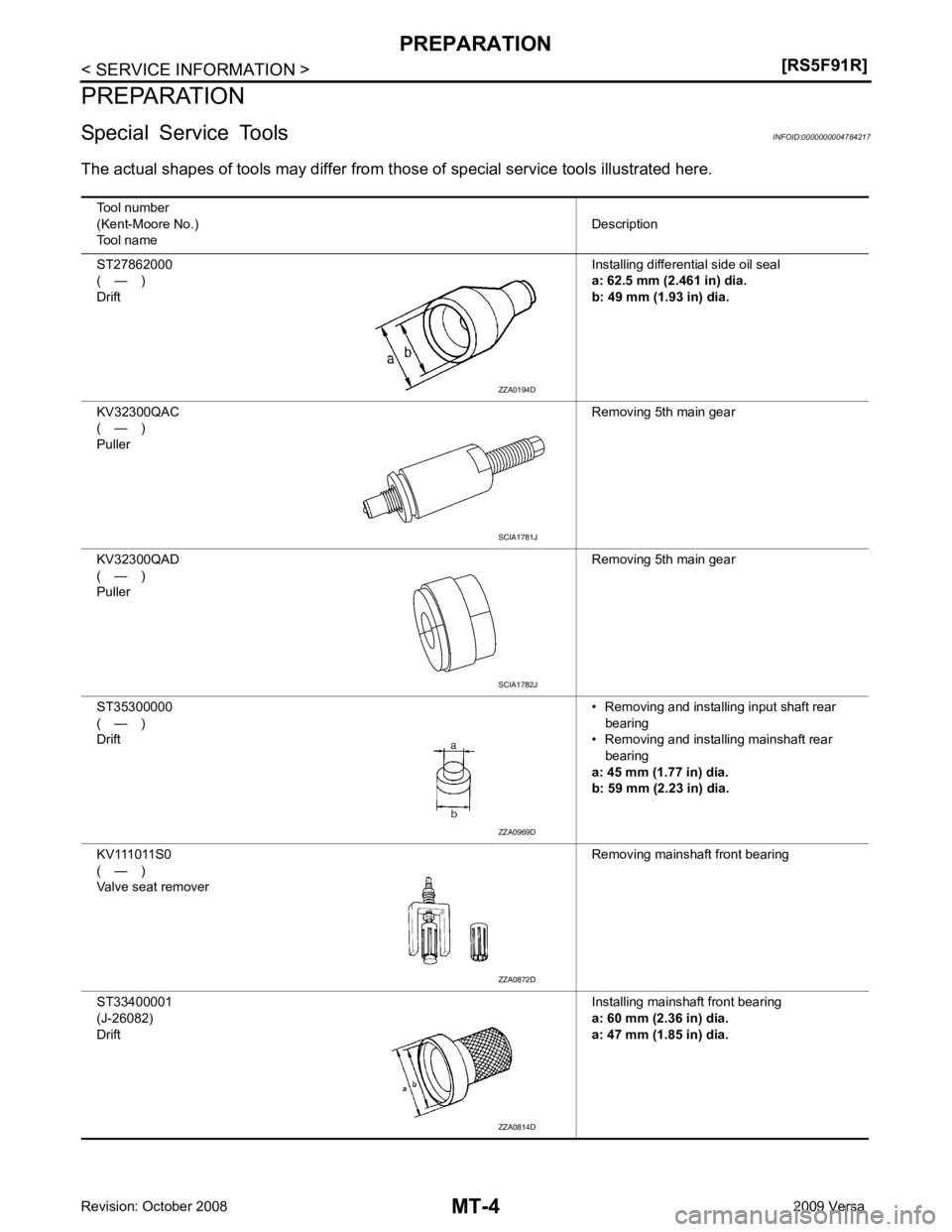
SCIA1781J
SCIA1782J
ZZA0872D
ZZA0814D
Page 3799 of 4331
![NISSAN TIIDA 2009 Service Repair Manual PREPARATION
MT-5
< SERVICE INFORMATION >
[RS5F91R] D
E
F
G H
I
J
K L
M A
B MT
N
O P
Commercial Service Tools
INFOID:0000000004784218
KV40100900
( — )
Drift Installing input shaft front bearing
a: 52 NISSAN TIIDA 2009 Service Repair Manual PREPARATION
MT-5
< SERVICE INFORMATION >
[RS5F91R] D
E
F
G H
I
J
K L
M A
B MT
N
O P
Commercial Service Tools
INFOID:0000000004784218
KV40100900
( — )
Drift Installing input shaft front bearing
a: 52](/img/5/57398/w960_57398-3798.png)
PREPARATION
MT-5
< SERVICE INFORMATION >
[RS5F91R] D
E
F
G H
I
J
K L
M A
B MT
N
O P
Commercial Service Tools
INFOID:0000000004784218
KV40100900
( — )
Drift Installing input shaft front bearing
a: 52 mm (2.05 in) dia.
a: 39.5 mm (1.55 in) dia.
KV32300QAE
( — )
Drift Installing differential side bearing outer race
a: 65 mm (2.56 in) dia.
a: 63 mm (2.48 in) dia.
ST33052000
( — )
Drift Removing differential side bearing
a: 22 mm (0.87 in) dia.
a: 28 mm (1.10 in) dia.
KV40104920
( — )
Drift Installing differential side bearing
a: 21.7 mm (0.85 in) dia.
a: 44.7 mm (1.76 in) dia.
Tool number
(Kent-Moore No.)
Tool name Description NT084
SCIA1783J
ZZA0969D
ZZA0969D
Tool name Description
Drift Removing input shaft front bearing
a: 38 mm (1.50 in) dia.
Drift Installing bushing
a: 14.5 mm (0.571 in) dia. S-NT063
S-NT063
Page 3800 of 4331
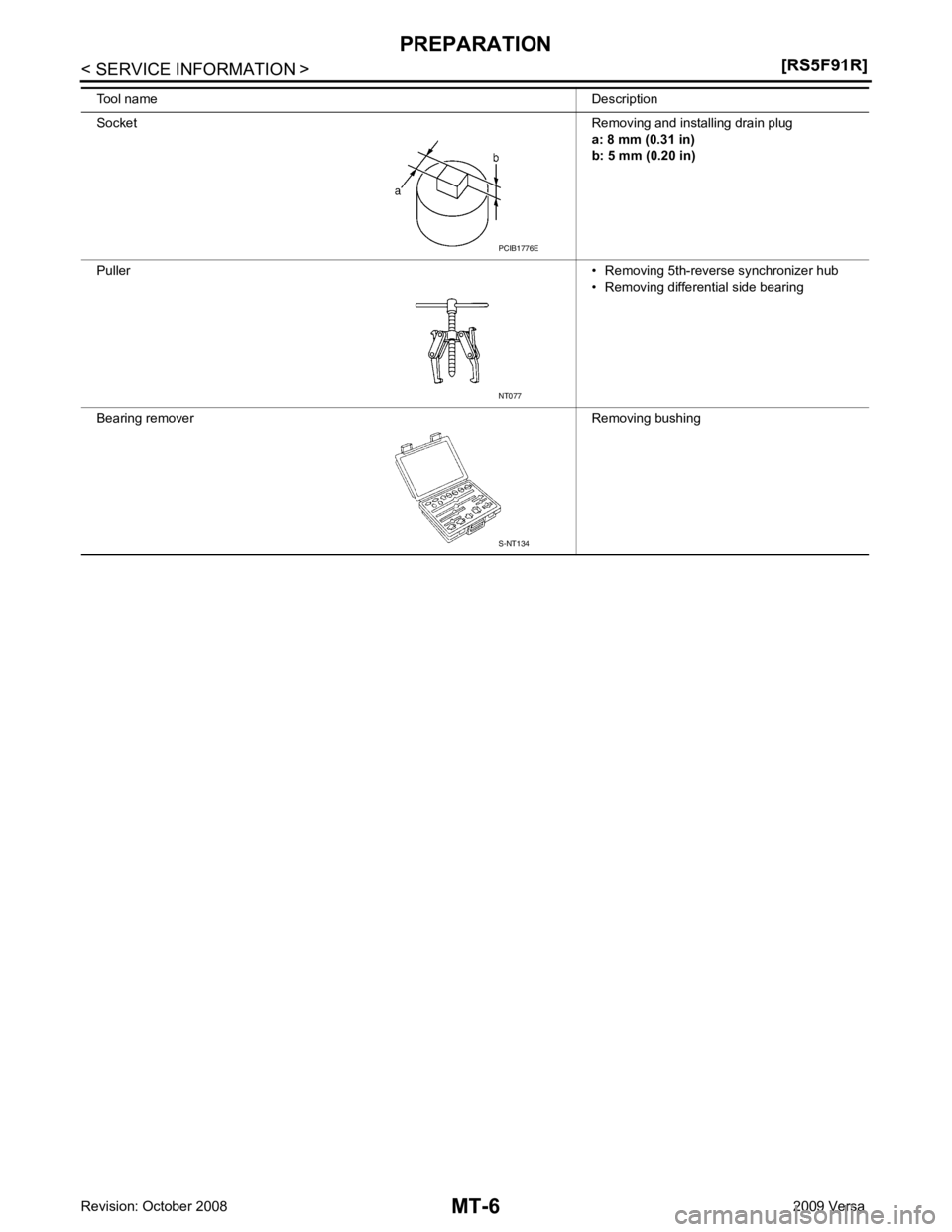
NT077
S-NT134