NISSAN X-TRAIL 2001 Service Repair Manual
Manufacturer: NISSAN, Model Year: 2001, Model line: X-TRAIL, Model: NISSAN X-TRAIL 2001Pages: 3833, PDF Size: 39.49 MB
Page 2671 of 3833
PR-1
PROPELLER SHAFT
D DRIVELINE/AXLE
CONTENTS
C
E
F
G
H
I
J
K
L
M
SECTION
A
B
PR
PROPELLER SHAFT
REAR PROPELLER SHAFT ...................................... 2
On-Vehicle Inspection .............................................. 2
PROPELLER SHAFT RUNOUT INSPECTION ..... 2
APPEARANCE AND NOISE INSPECTION .......... 2
Removal and Installation .......................................... 3
REMOVAL ............................................................. 3
INSPECTION AFTER REMOVAL ......................... 3
INSTALLATION ..................................................... 4SERVICE DATA AND SPECIFICATIONS (SDS) ........ 5
General Specifications ......................................... ..... 5
Propeller Shaft Axial Play ......................................... 5
Propeller Shaft Vibration ........................................... 5
Page 2672 of 3833
PR-2
REAR PROPELLER SHAFT
REAR PROPELLER SHAFT
PFP:37000
On-Vehicle InspectionEDS000ZW
PROPELLER SHAFT RUNOUT INSPECTION
If vibration occurs during driving at high speed, check for propeller shaft runout first.
1. Lift vehicle.
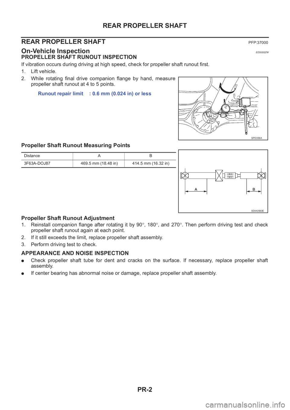
2. While rotating final drive companion flange by hand, measure
propeller shaft runout at 4 to 5 points.
Propeller Shaft Runout Measuring Points
Propeller Shaft Runout Adjustment
1. Reinstall companion flange after rotating it by 90°, 180°, and 270°. Then perform driving test and check
propeller shaft runout again at each point.
2. If it still exceeds the limit, replace propeller shaft assembly.
3. Perform driving test to check.
APPEARANCE AND NOISE INSPECTION
●Check propeller shaft tube for dent and cracks on the surface. If necessary, replace propeller shaft
assembly.
●If center bearing has abnormal noise or damage, replace propeller shaft assembly. Runout repair limit : 0.6 mm (0.024 in) or less
SPD356A
Distance A B
3F63A-DOJ87 469.5 mm (18.48 in) 414.5 mm (16.32 in)
SDIA0560E
Page 2673 of 3833
REAR PROPELLER SHAFT
PR-3
C
E
F
G
H
I
J
K
L
MA
B
PR
Removal and InstallationEDS000ZX
REMOVAL
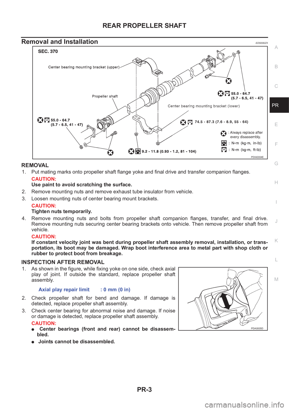
1. Put mating marks onto propeller shaft flange yoke and final drive and transfer companion flanges.
CAUTION:
Use paint to avoid scratching the surface.
2. Remove mounting nuts and remove exhaust tube insulator from vehicle.
3. Loosen mounting nuts of center bearing mount brackets.
CAUTION:
Tighten nuts temporarily.
4. Remove mounting nuts and bolts from propeller shaft companion flanges, transfer, and final drive.
Remove mounting nuts securing center bearing brackets onto vehicle. Then remove propeller shaft from
vehicle.
CAUTION:
If constant velocity joint was bent during propeller shaft assembly removal, installation, or trans-
portation, its boot may be damaged. Wrap boot interference area to metal part with shop cloth or
rubber to protect boot from breakage.
INSPECTION AFTER REMOVAL
1. As shown in the figure, while fixing yoke on one side, check axial
play of joint. If outside the standard, replace propeller shaft
assembly.
2. Check propeller shaft for bend and damage. If damage is
detected, replace propeller shaft assembly.
3. Check center bearing for abnormal noise and damage. If noise
or damage is detected, replace propeller shaft assembly.
CAUTION:
● Center bearings (front and rear) cannot be disassem-
bled.
● Joints cannot be disassembled.
PDIA0004E
Axial play repair limit : 0 mm (0 in)
PDA0005D
Page 2674 of 3833
PR-4
REAR PROPELLER SHAFT
INSTALLATION
Paying attention to following items, install in the reverse order of removal.
●Align mating marks to install propeller shaft, and tighten to specified torque.
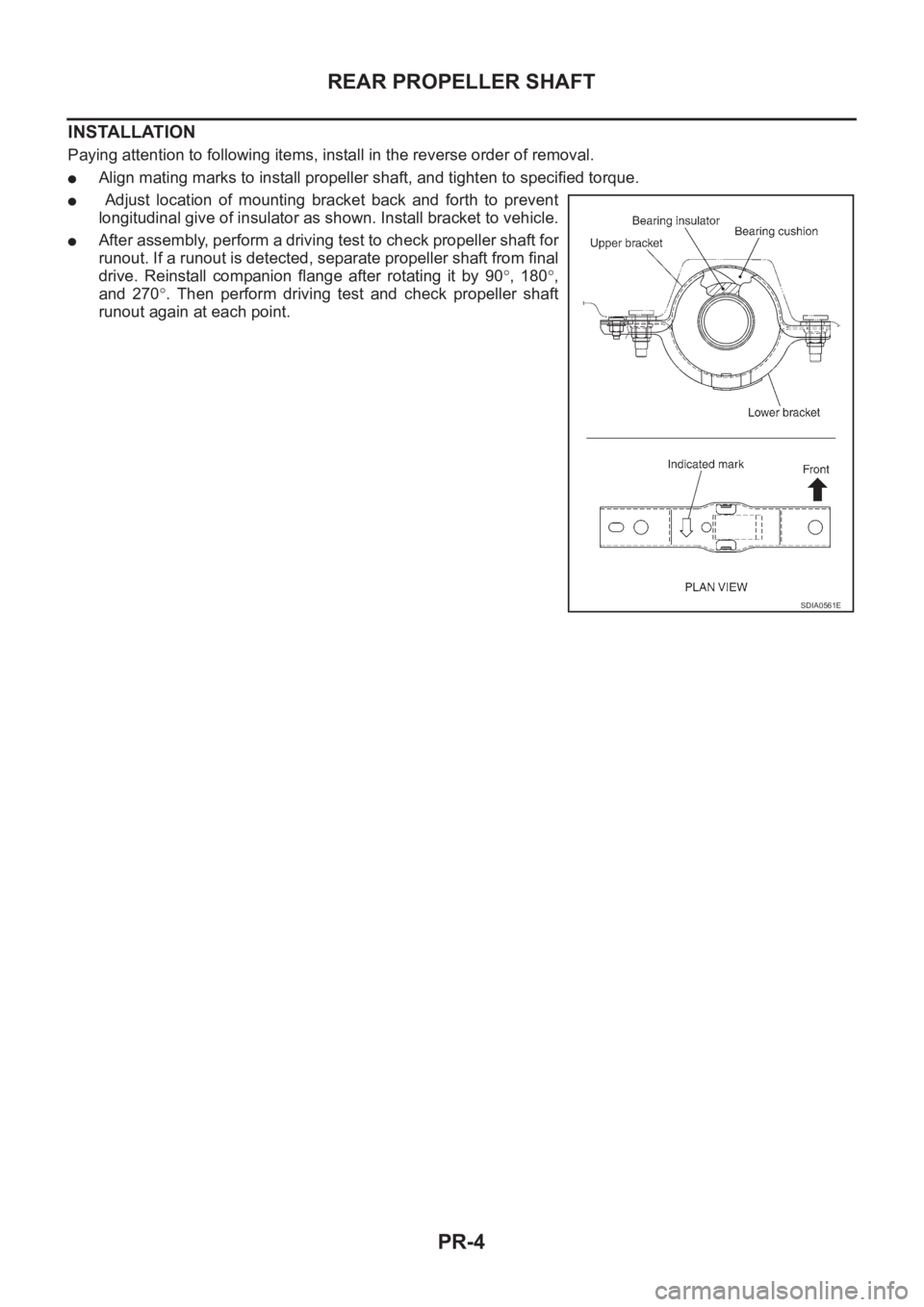
● Adjust location of mounting bracket back and forth to prevent
longitudinal give of insulator as shown. Install bracket to vehicle.
●After assembly, perform a driving test to check propeller shaft for
runout. If a runout is detected, separate propeller shaft from final
drive. Reinstall companion flange after rotating it by 90°, 180°,
and 270°. Then perform driving test and check propeller shaft
runout again at each point.
SDIA0561E
Page 2675 of 3833
SERVICE DATA AND SPECIFICATIONS (SDS)
PR-5
C
E
F
G
H
I
J
K
L
MA
B
PR
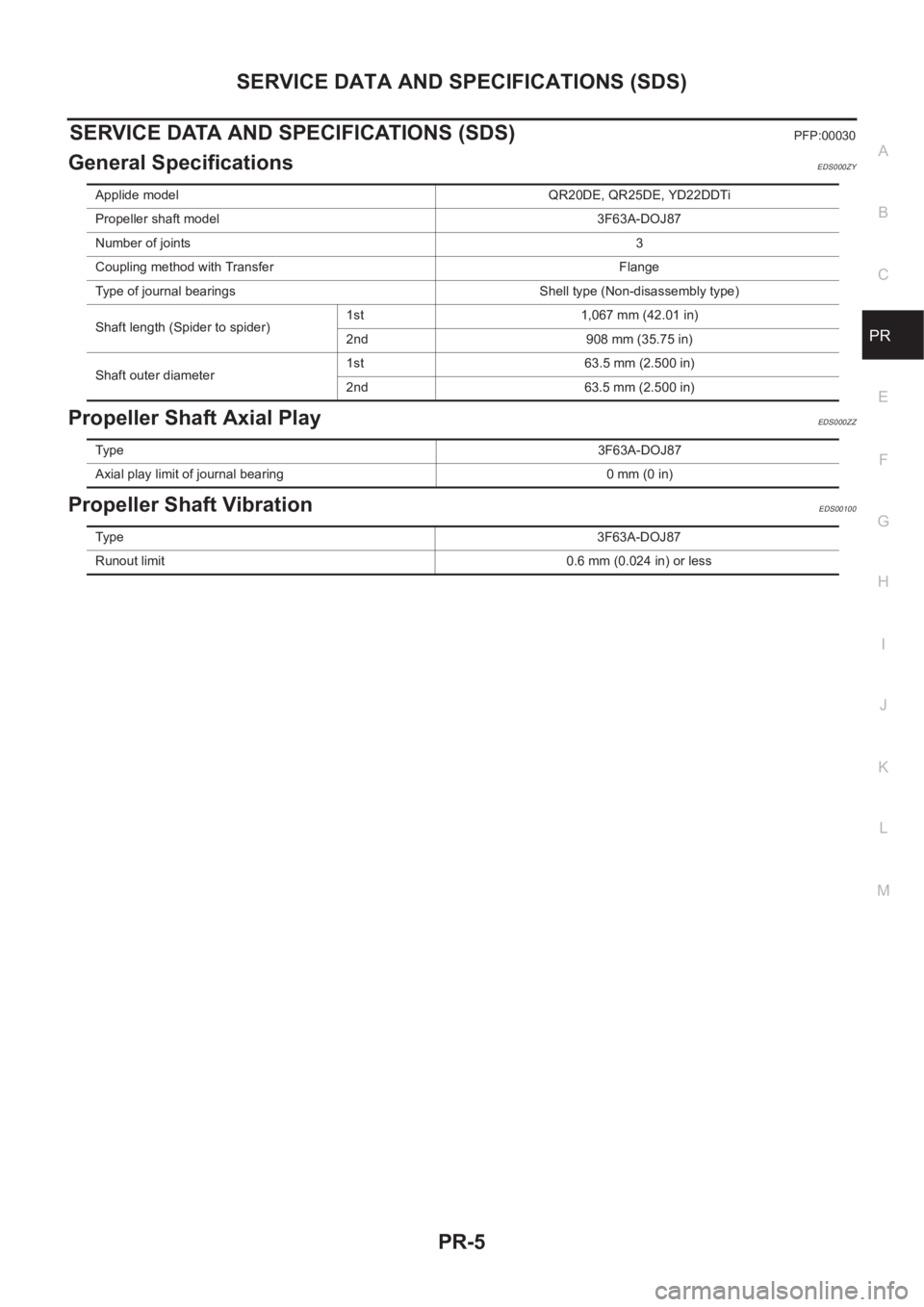
SERVICE DATA AND SPECIFICATIONS (SDS)PFP:00030
General SpecificationsEDS000ZY
Propeller Shaft Axial PlayEDS000ZZ
Propeller Shaft VibrationEDS00100
Applide model QR20DE, QR25DE, YD22DDTi
Propeller shaft model 3F63A-DOJ87
Number of joints3
Coupling method with Transfer Flange
Type of journal bearings Shell type (Non-disassembly type)
Shaft length (Spider to spider)1st 1,067 mm (42.01 in)
2nd 908 mm (35.75 in)
Shaft outer diameter1st 63.5 mm (2.500 in)
2nd 63.5 mm (2.500 in)
Ty p e3F63A-DOJ87
Axial play limit of journal bearing 0 mm (0 in)
Ty p e3F63A-DOJ87
Runout limit 0.6 mm (0.024 in) or less
Page 2676 of 3833
PR-6
SERVICE DATA AND SPECIFICATIONS (SDS)
Page 2677 of 3833
RFD-1
REAR FINAL DRIVE
D DRIVELINE/AXLE
CONTENTS
C
E
F
G
H
I
J
K
L
M
SECTION
A
B
RFD
REAR FINAL DRIVE
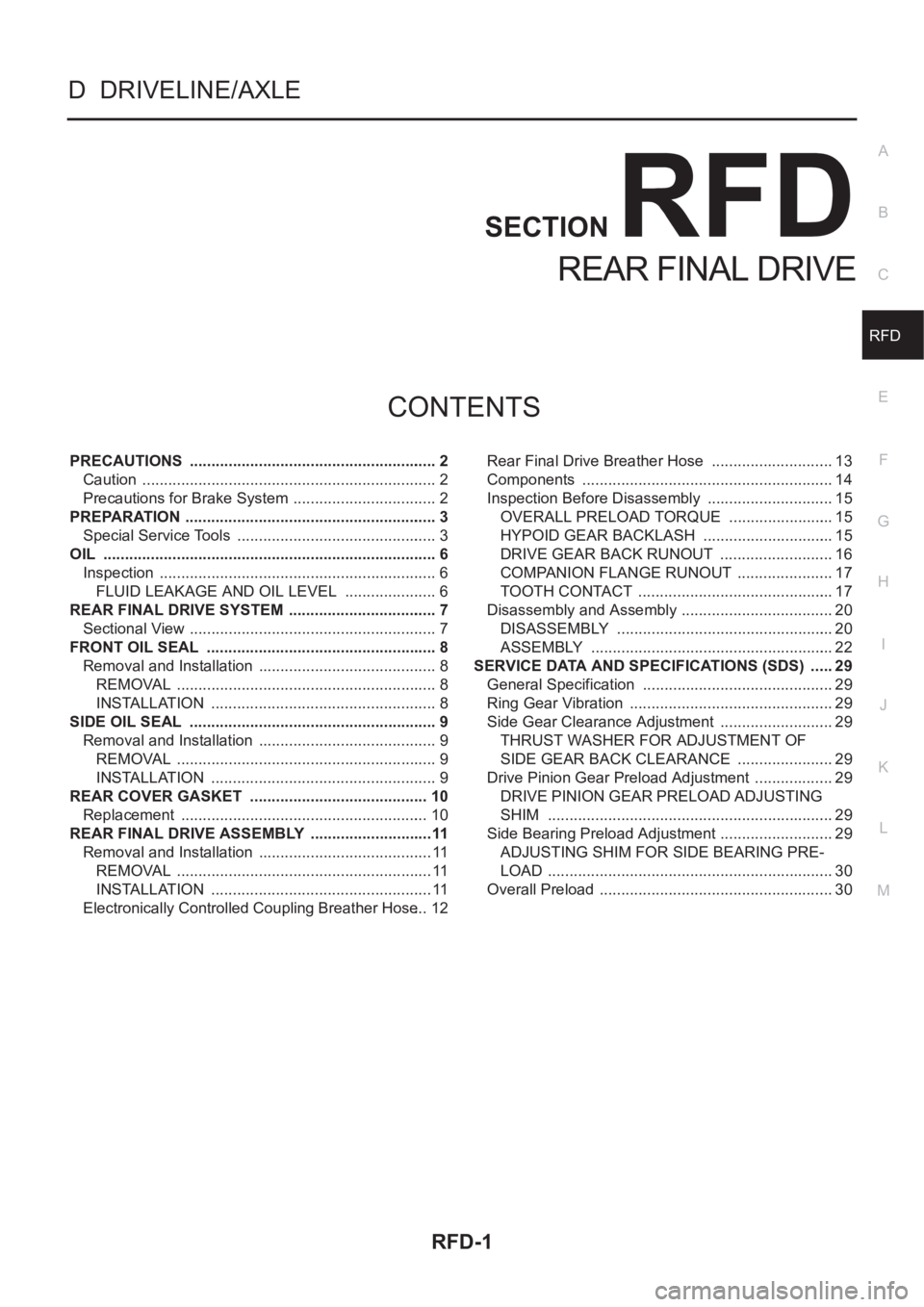
PRECAUTIONS .......................................................... 2
Caution ..................................................................... 2
Precautions for Brake System .................................. 2
PREPARATION ........................................................... 3
Special Service Tools ............................................... 3
OIL .............................................................................. 6
Inspection ................................................................. 6
FLUID LEAKAGE AND OIL LEVEL ...................... 6
REAR FINAL DRIVE SYSTEM ................................... 7
Sectional View .......................................................... 7
FRONT OIL SEAL ................................................. ..... 8
Removal and Installation .......................................... 8
REMOVAL ............................................................. 8
INSTALLATION ..................................................... 8
SIDE OIL SEAL .......................................................... 9
Removal and Installation .......................................... 9
REMOVAL ............................................................. 9
INSTALLATION ..................................................... 9
REAR COVER GASKET .......................................... 10
Replacement .......................................................... 10
REAR FINAL DRIVE ASSEMBLY .............................11
Removal and Installation ......................................... 11
REMOVAL ............................................................ 11
INSTALLATION .................................................... 11
Electronically Controlled Coupling Breather Hose ... 12Rear Final Drive Breather Hose ............................. 13
Components ........................................................... 14
Inspection Before Disassembly .............................. 15
OVERALL PRELOAD TORQUE ......................... 15
HYPOID GEAR BACKLASH ............................... 15
DRIVE GEAR BACK RUNOUT ........................... 16
COMPANION FLANGE RUNOUT ....................... 17
TOOTH CONTACT .............................................. 17
Disassembly and Assembly .................................... 20
DISASSEMBLY ................................................... 20
ASSEMBLY ......................................................... 22
SERVICE DATA AND SPECIFICATIONS (SDS) ...... 29
General Specification ............................................. 29
Ring Gear Vibration ................................................ 29
Side Gear Clearance Adjustment ........................... 29
THRUST WASHER FOR ADJUSTMENT OF
SIDE GEAR BACK CLEARANCE ....................... 29
Drive Pinion Gear Preload Adjustment ................... 29
DRIVE PINION GEAR PRELOAD ADJUSTING
SHIM ................................................................... 29
Side Bearing Preload Adjustment ........................... 29
ADJUSTING SHIM FOR SIDE BEARING PRE-
LOAD ................................................................... 30
Overall Preload ....................................................... 30
Page 2678 of 3833
RFD-2
PRECAUTIONS
PRECAUTIONS
PFP:00001
CautionEDS00101
●Before starting diagnosis of the vehicle, understand symptoms well. Perform correct and systematic oper-
ations.
●Check for the correct installation status prior to removal or disassembly. When mating marks are required,
be sure they do not interfere with the function of the parts they are applied to.
●Carry out an overhaul in a clean work place. Using a dust proof room is recommended.
●Before disassembly, using steam or white gasoline, completely remove sand and mud from the exterior of
the unit, preventing them from entering into the unit during disassembly or assembly.
●Check appearance of the disassembled parts for damage, deformation, and abnormal wear. If a malfunc-
tion is detected, replace it with a new one.
●Normally replace lock pins, oil seals, and bearings with new ones every time they are removed.
●In principle, tighten bolts or nuts gradually in several steps working diagonally from inside to outside. If
tightening sequence is specified, observe it.
●Clean and flush the parts sufficiently and blow them dry.
●Be careful not to damage the sliding surfaces and mating surfaces.
●When applying sealant, remove the old sealant from the mounting surface; then remove any moisture, oil,
and foreign materials from the application and mounting surfaces.
●Always use shop paper for cleaning the inside of components.
●Avoid using cotton gloves or a shop cloth to prevent entering of lint.
●During assembly, observe the specified tightening torque, and apply new differential oil, Vaseline, or Nis-
san MP Special Grease No. 2, as specified for each vehicle, when necessary.
●Do not reuse drained oil. Discard waste oil after oil changes or part treatment in accordance with local
laws and regulations.
Precautions for Brake SystemEDS00102
●When installing rubber parts, final tightening must be carried out under unladen condition* with tires on
ground.
*: Fuel, radiator coolant and engine oil full. Spare tire, jack, hand tools and mats in designated positions.
●After installing removed suspension parts, check wheel alignment and adjust if necessary.
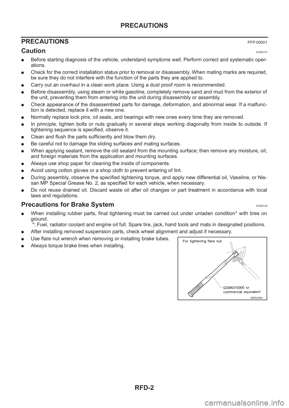
●Use flare nut wrench when removing or installing brake tubes.
●Always torque brake lines when installing.
SBR820BA
Page 2679 of 3833
PREPARATION
RFD-3
C
E
F
G
H
I
J
K
L
MA
B
RFD
PREPARATIONPFP:00002
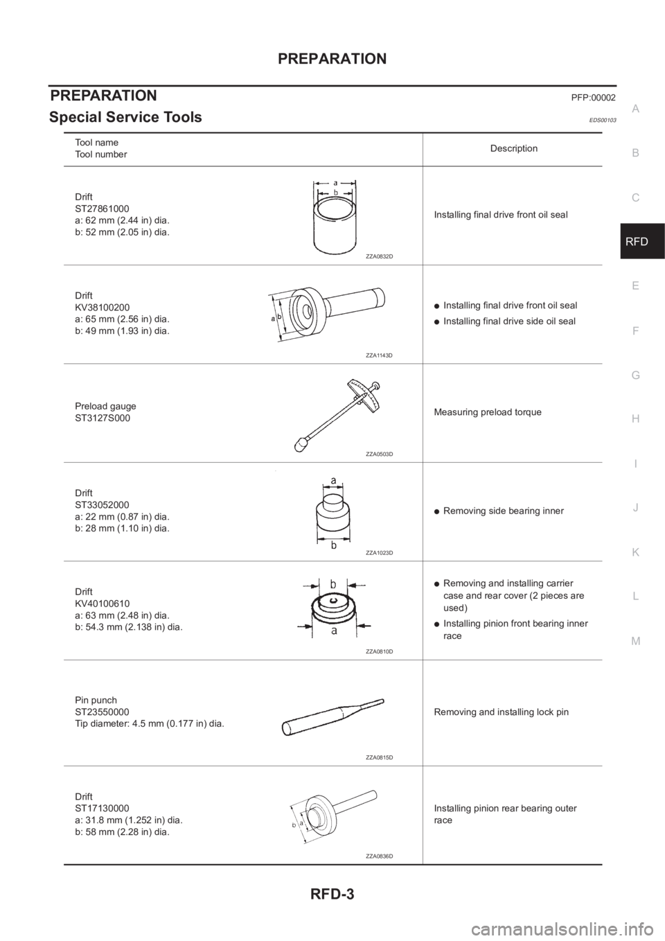
Special Service ToolsEDS00103
Tool name
Tool numberDescription
Drift
ST27861000
a: 62 mm (2.44 in) dia.
b: 52 mm (2.05 in) dia.Installing final drive front oil seal
Drift
KV38100200
a: 65 mm (2.56 in) dia.
b: 49 mm (1.93 in) dia.
●Installing final drive front oil seal
●Installing final drive side oil seal
Preload gauge
ST3127S000Measuring preload torque
Drift
ST33052000
a: 22 mm (0.87 in) dia.
b: 28 mm (1.10 in) dia.
●Removing side bearing inner
Drift
KV40100610
a: 63 mm (2.48 in) dia.
b: 54.3 mm (2.138 in) dia.
●Removing and installing carrier
case and rear cover (2 pieces are
used)
●Installing pinion front bearing inner
race
Pin punch
ST23550000
Tip diameter: 4.5 mm (0.177 in) dia.Removing and installing lock pin
Drift
ST17130000
a: 31.8 mm (1.252 in) dia.
b: 58 mm (2.28 in) dia.Installing pinion rear bearing outer
race
ZZA0832D
ZZA1143D
ZZA0503D
ZZA1023D
ZZA0810D
ZZA0815D
ZZA0836D
Page 2680 of 3833
RFD-4
PREPARATION
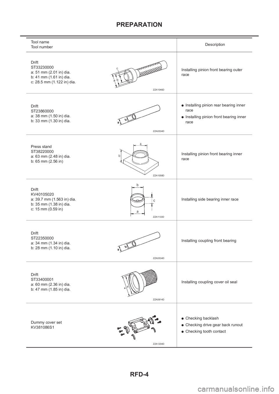
Drift
ST33230000
a: 51 mm (2.01 in) dia.
b: 41 mm (1.61 in) dia.
c: 28.5 mm (1.122 in) dia.Installing pinion front bearing outer
race
Drift
ST23860000
a: 38 mm (1.50 in) dia.
b: 33 mm (1.30 in) dia.
●Installing pinion rear bearing inner
race
●Installing pinion front bearing inner
race
Press stand
ST38220000
a: 63 mm (2.48 in) dia.
b: 65 mm (2.56 in)Installing pinion front bearing inner
race
Drift
KV40105020
a: 39.7 mm (1.563 in) dia.
b: 35 mm (1.38 in) dia.
c: 15 mm (0.59 in)Installing side bearing inner race
Drift
ST22350000
a: 34 mm (1.34 in) dia.
b: 28 mm (1.10 in) dia.Installing coupling front bearing
Drift
ST33400001
a: 60 mm (2.36 in) dia.
b: 47 mm (1.85 in) dia.Installing coupling cover oil seal
Dummy cover set
KV381086S1
●Checking backlash
●Checking drive gear back runout
●Checking tooth contact Tool name
Tool numberDescription
ZZA1046D
ZZA0534D
ZZA1058D
ZZA1133D
ZZA0534D
ZZA0814D
ZZA1204D