NISSAN X-TRAIL 2001 Service Repair Manual
X-TRAIL 2001
NISSAN
NISSAN
https://www.carmanualsonline.info/img/5/57405/w960_57405-0.png
NISSAN X-TRAIL 2001 Service Repair Manual
Trending: spare tire location, low oil pressure, stop start, tire pressure, Lt-25, automatic transmission, window
Page 2681 of 3833
PREPARATION
RFD-5
C
E
F
G
H
I
J
K
L
MA
B
RFD
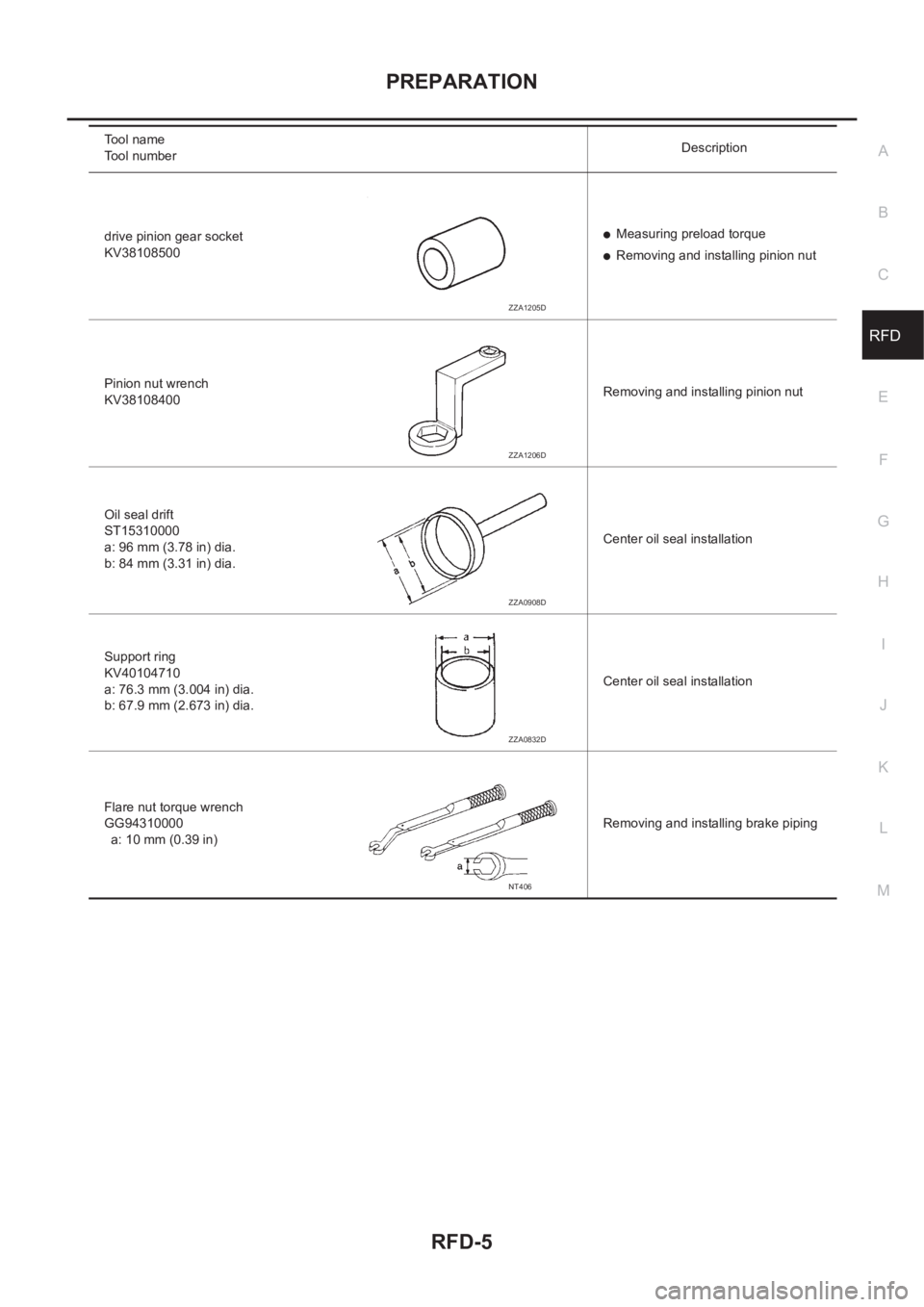
drive pinion gear socket
KV38108500●Measuring preload torque
●Removing and installing pinion nut
Pinion nut wrench
KV38108400Removing and installing pinion nut
Oil seal drift
ST15310000
a: 96 mm (3.78 in) dia.
b: 84 mm (3.31 in) dia.Center oil seal installation
Support ring
KV40104710
a: 76.3 mm (3.004 in) dia.
b: 67.9 mm (2.673 in) dia.Center oil seal installation
Flare nut torque wrench
GG94310000
a: 10 mm (0.39 in)Removing and installing brake piping Tool name
Tool numberDescription
ZZA1205D
ZZA1206D
ZZA0908D
ZZA0832D
NT406
Page 2682 of 3833
RFD-6
OIL
OIL
PFP:00024
InspectionEDS00104
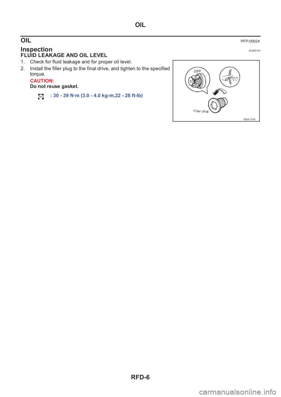
FLUID LEAKAGE AND OIL LEVEL
1. Check for fluid leakage and for proper oil level.
2. Install the filler plug to the final drive, and tighten to the specified
torque.
CAUTION:
Do not reuse gasket.
: 30 - 39 N·m (3.0 - 4.0 kg-m,22 - 28 ft-lb)
SDIA1151E
Page 2683 of 3833
REAR FINAL DRIVE SYSTEM
RFD-7
C
E
F
G
H
I
J
K
L
MA
B
RFD
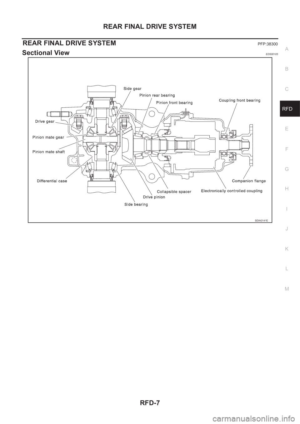
REAR FINAL DRIVE SYSTEMPFP:38300
Sectional ViewEDS00105
SDIA0141E
Page 2684 of 3833
RFD-8
FRONT OIL SEAL
FRONT OIL SEAL
PFP:38189
Removal and InstallationEDS00106
REMOVAL
1. Remove propeller shaft. Refer to PR-3, "REMOVAL" .
2. Paint mating marks on the final drive companion flange and the thread edge of the electronically con-
trolled coupling.
CAUTION:
Use paint to avoid scratching the surface.
3. Using a differential flange tool, remove companion flange nut to remove companion flange.
4. Using a screwdriver or similar tool, remove oil seal.
INSTALLATION
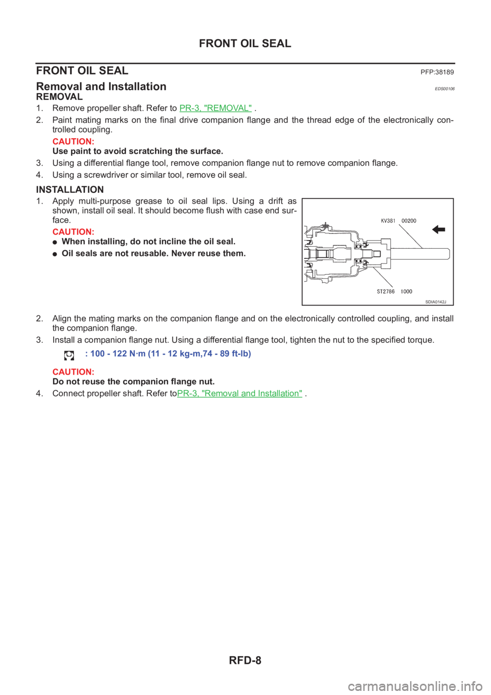
1. Apply multi-purpose grease to oil seal lips. Using a drift as
shown, install oil seal. It should become flush with case end sur-
face.
CAUTION:
●When installing, do not incline the oil seal.
●Oil seals are not reusable. Never reuse them.
2. Align the mating marks on the companion flange and on the electronically controlled coupling, and install
the companion flange.
3. Install a companion flange nut. Using a differential flange tool, tighten the nut to the specified torque.
CAUTION:
Do not reuse the companion flange nut.
4. Connect propeller shaft. Refer toPR-3, "
Removal and Installation" .
SDIA0142J
: 100 - 122 N·m (11 - 12 kg-m,74 - 89 ft-lb)
Page 2685 of 3833
SIDE OIL SEAL
RFD-9
C
E
F
G
H
I
J
K
L
MA
B
RFD
SIDE OIL SEALPFP:38343
Removal and InstallationEDS00107
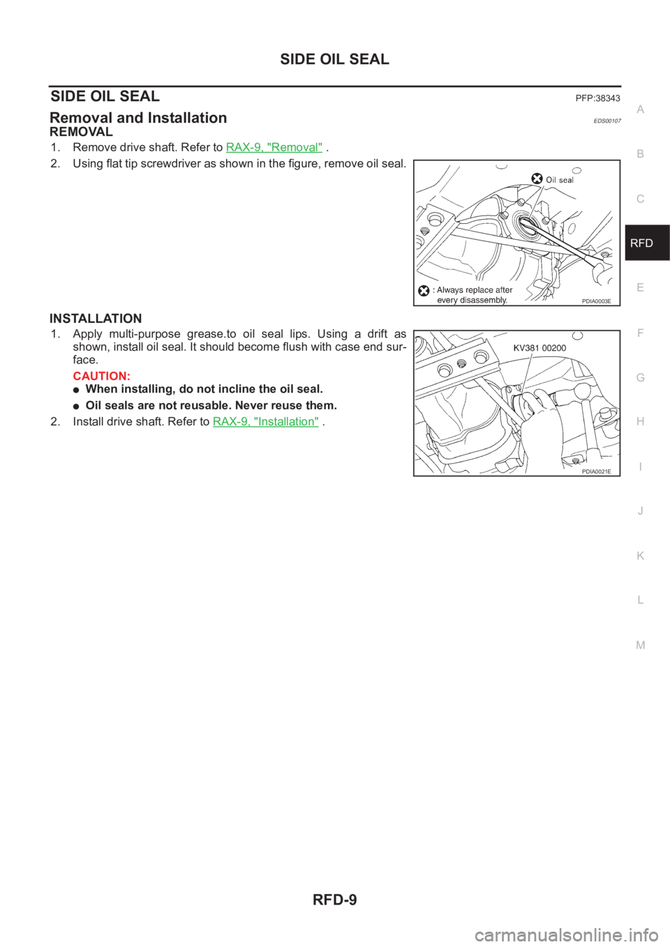
REMOVAL
1. Remove drive shaft. Refer to RAX-9, "Removal" .
2. Using flat tip screwdriver as shown in the figure, remove oil seal.
INSTALLATION
1. Apply multi-purpose grease.to oil seal lips. Using a drift as
shown, install oil seal. It should become flush with case end sur-
face.
CAUTION:
●When installing, do not incline the oil seal.
●Oil seals are not reusable. Never reuse them.
2. Install drive shaft. Refer to RAX-9, "
Installation" .
PDIA0003E
PDIA0021E
Page 2686 of 3833
RFD-10
REAR COVER GASKET
REAR COVER GASKET
PFP:38320
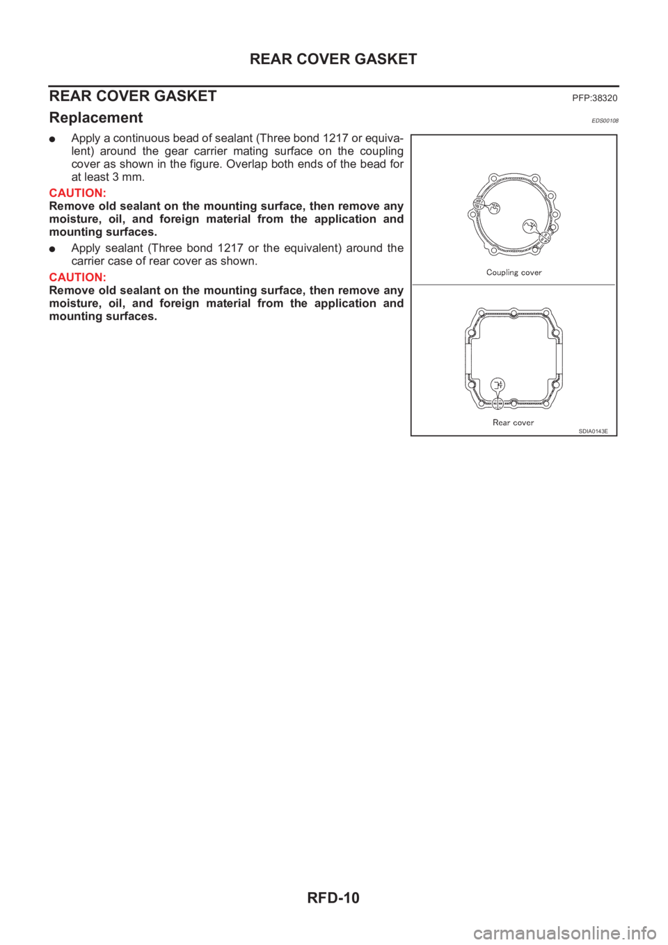
ReplacementEDS00108
●Apply a continuous bead of sealant (Three bond 1217 or equiva-
lent) around the gear carrier mating surface on the coupling
cover as shown in the figure. Overlap both ends of the bead for
at least 3 mm.
CAUTION:
Remove old sealant on the mounting surface, then remove any
moisture, oil, and foreign material from the application and
mounting surfaces.
●Apply sealant (Three bond 1217 or the equivalent) around the
carrier case of rear cover as shown.
CAUTION:
Remove old sealant on the mounting surface, then remove any
moisture, oil, and foreign material from the application and
mounting surfaces.
SDIA0143E
Page 2687 of 3833
REAR FINAL DRIVE ASSEMBLY
RFD-11
C
E
F
G
H
I
J
K
L
MA
B
RFD
REAR FINAL DRIVE ASSEMBLYPFP:38300
Removal and InstallationEDS00109
REMOVAL
1. Remove exhaust center tube.Refer to EX-2, "EXHAUST SYSTEM" .
2. Remove propeller shaft. Refer to PR-3, "
Removal and Installation" .
3. Remove drive shaft. Refer to RAX-9, "
Removal and Installation" .
4. Remove rear suspension member. Refer to RSU-5, "
Components" .
5. Remove air breather hose (for electronically controlled coupling and for rear final drive). Refer to RFD-12,
"Electronically Controlled Coupling Breather Hose" ,RFD-13, "Rear Final Drive Breather Hose" .
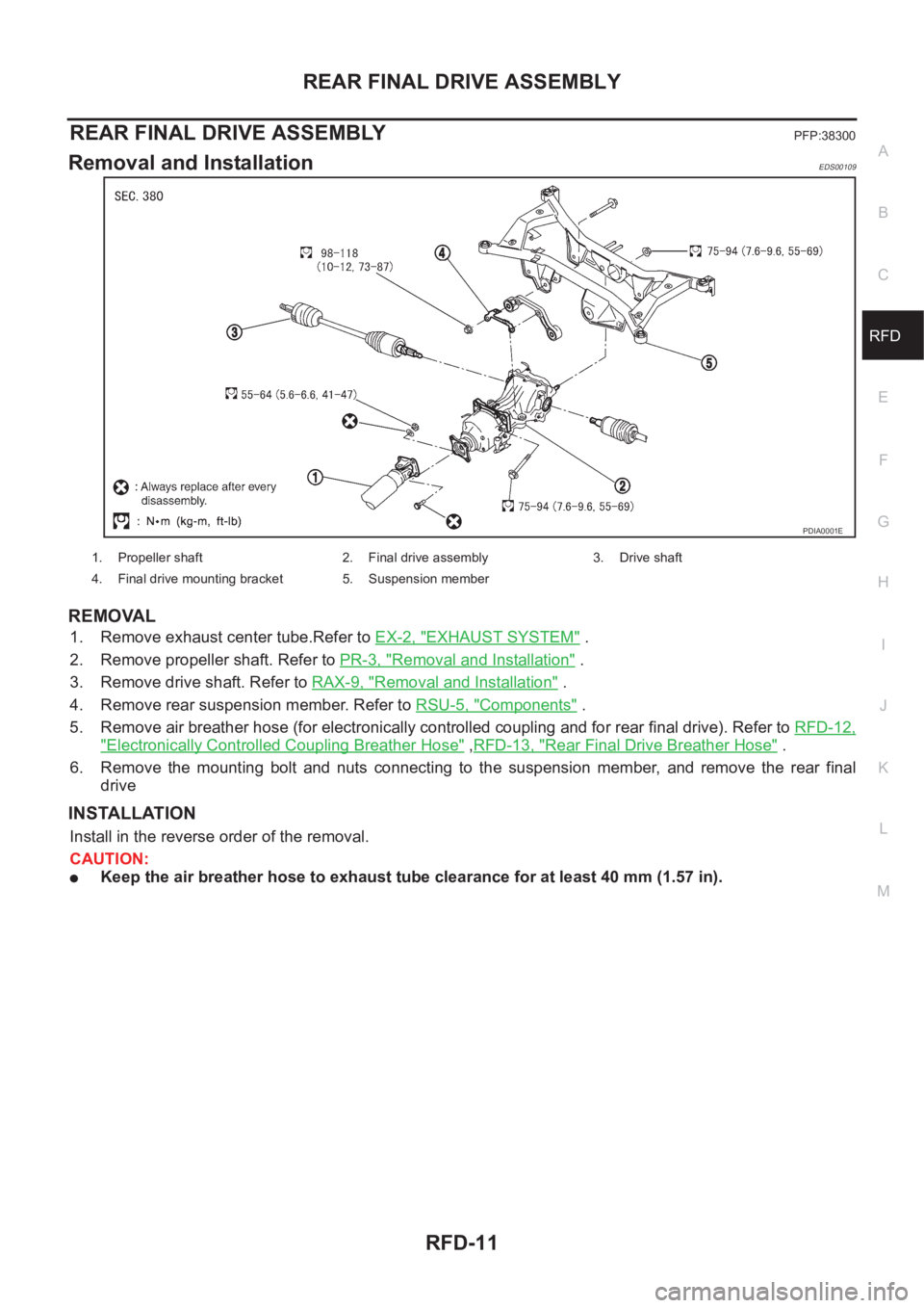
6. Remove the mounting bolt and nuts connecting to the suspension member, and remove the rear final
drive
INSTALLATION
Install in the reverse order of the removal.
CAUTION:
●Keep the air breather hose to exhaust tube clearance for at least 40 mm (1.57 in).
PDIA0001E
1. Propeller shaft 2. Final drive assembly 3. Drive shaft
4. Final drive mounting bracket 5. Suspension member
Page 2688 of 3833
RFD-12
REAR FINAL DRIVE ASSEMBLY
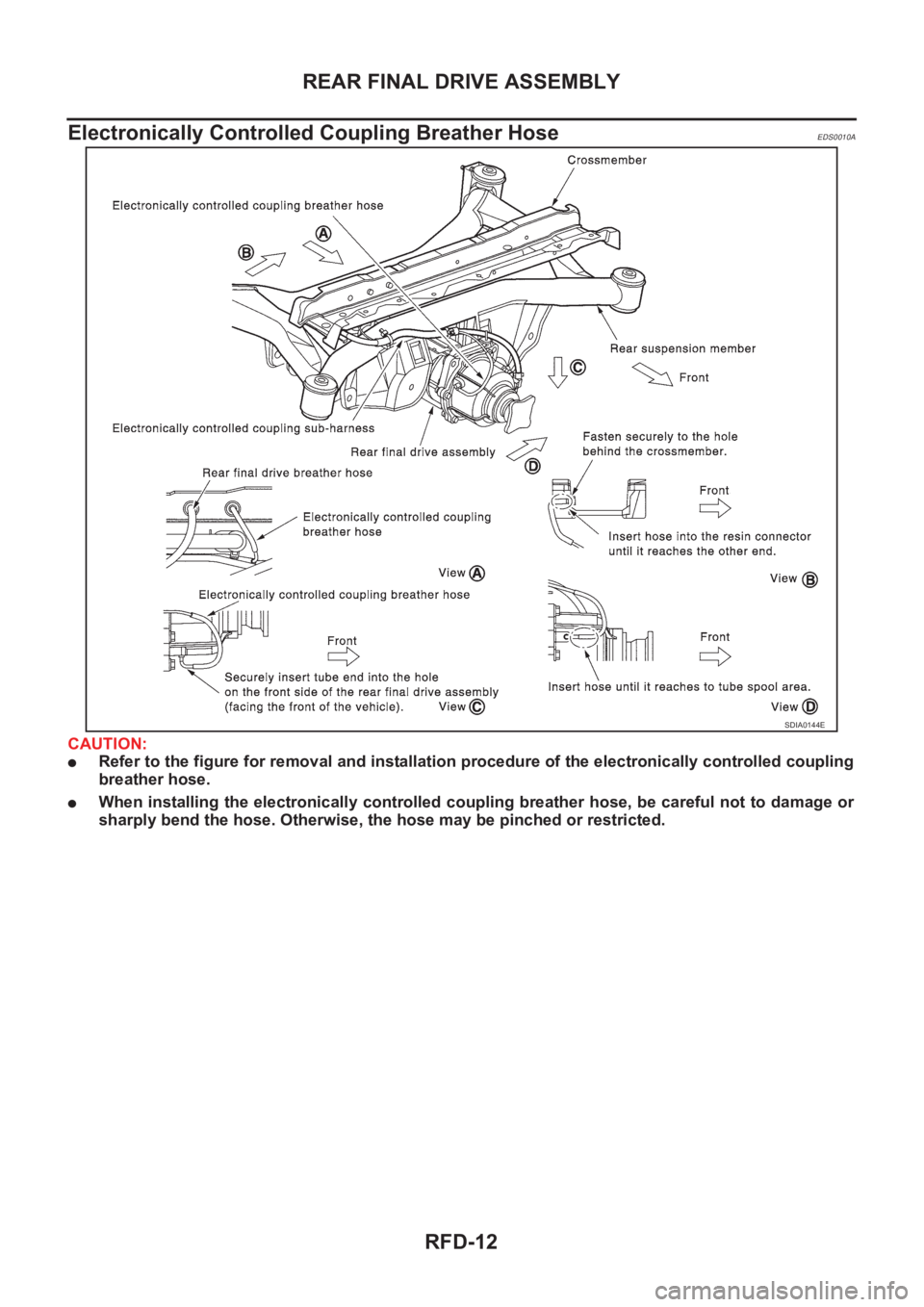
Electronically Controlled Coupling Breather Hose
EDS0010A
CAUTION:
●Refer to the figure for removal and installation procedure of the electronically controlled coupling
breather hose.
●When installing the electronically controlled coupling breather hose, be careful not to damage or
sharply bend the hose. Otherwise, the hose may be pinched or restricted.
SDIA0144E
Page 2689 of 3833
REAR FINAL DRIVE ASSEMBLY
RFD-13
C
E
F
G
H
I
J
K
L
MA
B
RFD
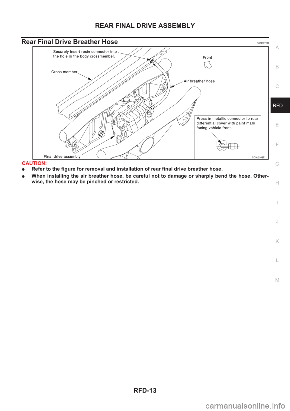
Rear Final Drive Breather HoseEDS0010B
CAUTION:
●Refer to the figure for removal and installation of rear final drive breather hose.
●When installing the air breather hose, be careful not to damage or sharply bend the hose. Other-
wise, the hose may be pinched or restricted.
SDIA0109E
Page 2690 of 3833
RFD-14
REAR FINAL DRIVE ASSEMBLY
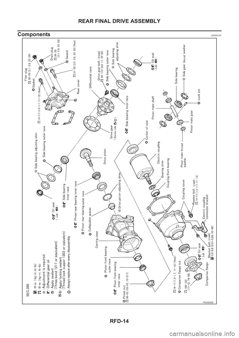
Components
EDS0010C
PDIA0002E
Trending: steering pump, heater, phone, wheel size, AUX, fuses, valve
