NISSAN X-TRAIL 2003 Electronic Repair Manual
Manufacturer: NISSAN, Model Year: 2003, Model line: X-TRAIL, Model: NISSAN X-TRAIL 2003Pages: 3066, PDF Size: 51.47 MB
Page 2531 of 3066
CHASSIS AND BODY MAINTENANCE
MA-39
C
D
E
F
G
H
I
J
K
MA
B
MA
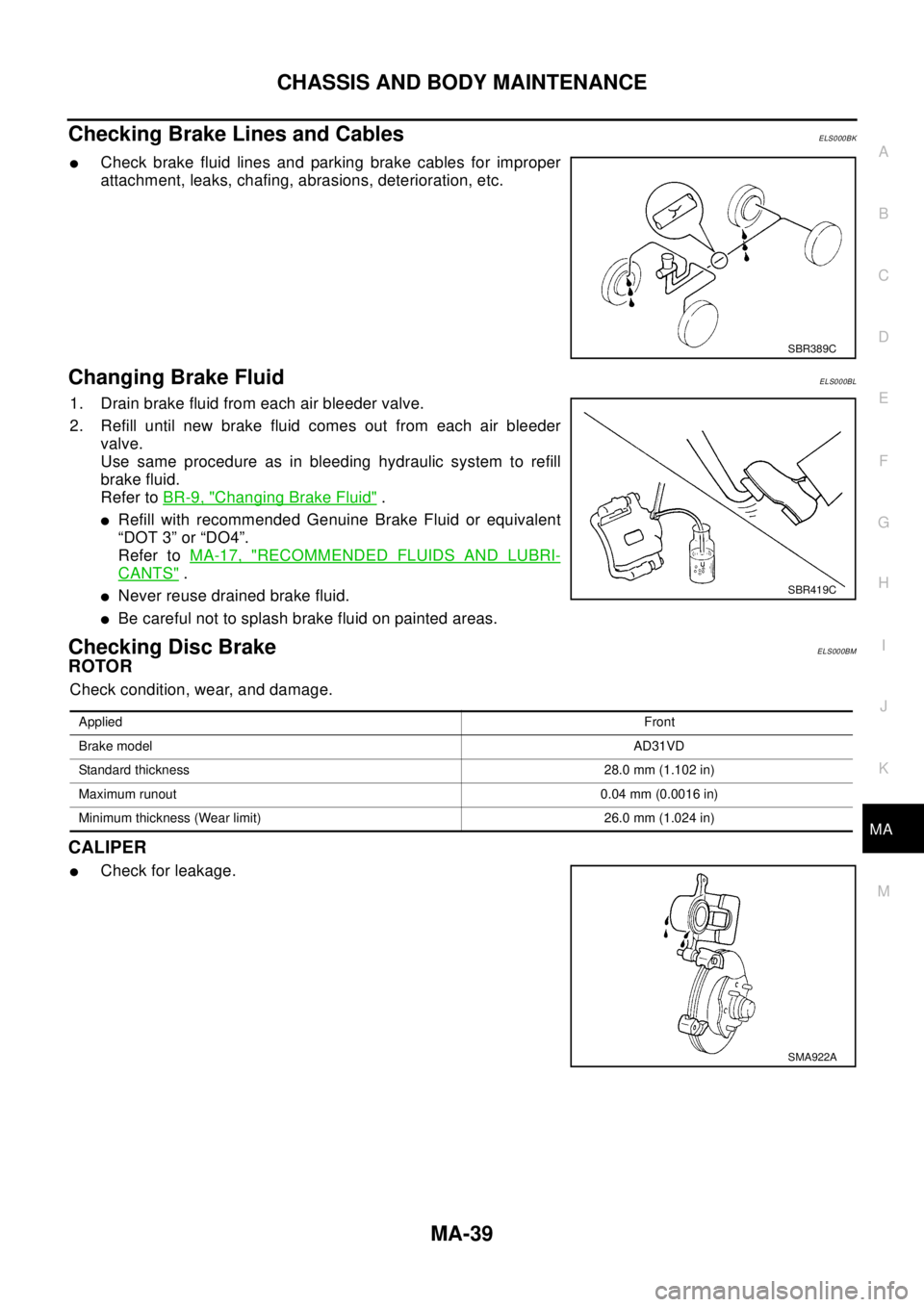
Checking Brake Lines and CablesELS000BK
lCheck brake fluid lines and parking brake cables for improper
attachment, leaks, chafing, abrasions, deterioration, etc.
Changing Brake FluidELS000BL
1. Drain brake fluid from each air bleeder valve.
2. Refill until new brake fluid comes out from each air bleeder
valve.
Use same procedure as in bleeding hydraulic system to refill
brake fluid.
Refer toBR-9, "
Changing Brake Fluid".
lRefill with recommended Genuine Brake Fluid or equivalent
“DOT 3” or “DO4”.
Refer toMA-17, "
RECOMMENDED FLUIDS AND LUBRI-
CANTS".
lNever reuse drained brake fluid.
lBe careful not to splash brake fluid on painted areas.
Checking Disc BrakeELS000BM
ROTOR
Check condition, wear, and damage.
CALIPER
lCheck for leakage.
SBR389C
SBR419C
AppliedFront
Brake modelAD31VD
Standard thickness 28.0 mm (1.102 in)
Maximum runout0.04 mm (0.0016 in)
Minimum thickness (Wear limit) 26.0 mm (1.024 in)
SMA922A
Page 2532 of 3066
MA-40
CHASSIS AND BODY MAINTENANCE
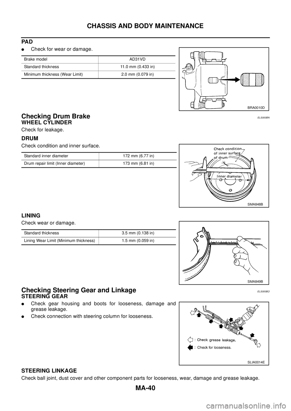
PA D
lCheck for wear or damage.
Checking Drum BrakeELS000BN
WHEEL CYLINDER
Check for leakage.
DRUM
Check condition and inner surface.
LINING
Check wear or damage.
Checking Steering Gear and LinkageELS000BO
STEERING GEAR
lCheck gear housing and boots for looseness, damage and
grease leakage.
lCheck connection with steering column for looseness.
STEERING LINKAGE
Check ball joint, dust cover and other component parts for looseness, wear, damage and grease leakage.
Brake model AD31VD
Standard thickness 11.0 mm (0.433 in)
Minimum thickness (Wear Limit) 2.0 mm (0.079 in)
BRA0010D
Standard inner diameter 172 mm (6.77 in)
Drum repair limit (Inner diameter) 173 mm (6.81 in)
SMA848B
Standard thickness 3.5 mm (0.138 in)
Lining Wear Limit (Minimum thickness) 1.5 mm (0.059 in)
SMA849B
SLIA0014E
Page 2533 of 3066
CHASSIS AND BODY MAINTENANCE
MA-41
C
D
E
F
G
H
I
J
K
MA
B
MA
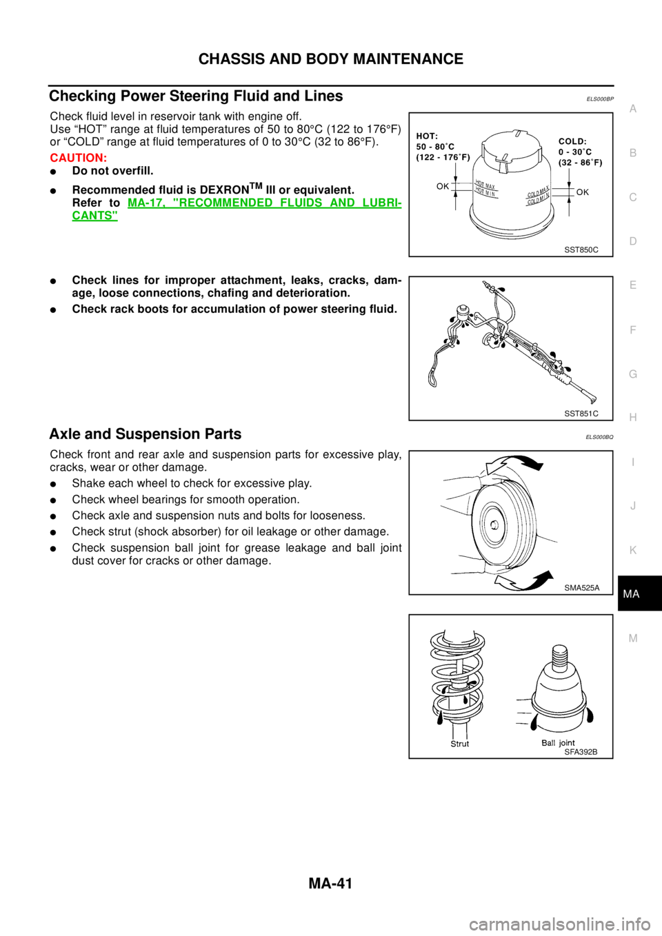
Checking Power Steering Fluid and LinesELS000BP
Check fluid level in reservoir tank with engine off.
Use “HOT” range at fluid temperatures of 50 to 80°C (122 to 176°F)
or “COLD” range at fluid temperatures of 0 to 30°C(32to86°F).
CAUTION:
lDo not overfill.
lRecommended fluid is DEXRONTMIII or equivalent.
Refer toMA-17, "
RECOMMENDED FLUIDS AND LUBRI-
CANTS"
lCheck lines for improper attachment, leaks, cracks, dam-
age, loose connections, chafing and deterioration.
lCheck rack boots for accumulation of power steering fluid.
Axle and Suspension PartsELS000BQ
Check front and rear axle and suspension parts for excessive play,
cracks, wear or other damage.
lShake each wheel to check for excessive play.
lCheck wheel bearings for smooth operation.
lCheck axle and suspension nuts and bolts for looseness.
lCheck strut (shock absorber) for oil leakage or other damage.
lCheck suspension ball joint for grease leakage and ball joint
dust cover for cracks or other damage.
SST850C
SST851C
SMA525A
SFA392B
Page 2534 of 3066
MA-42
CHASSIS AND BODY MAINTENANCE
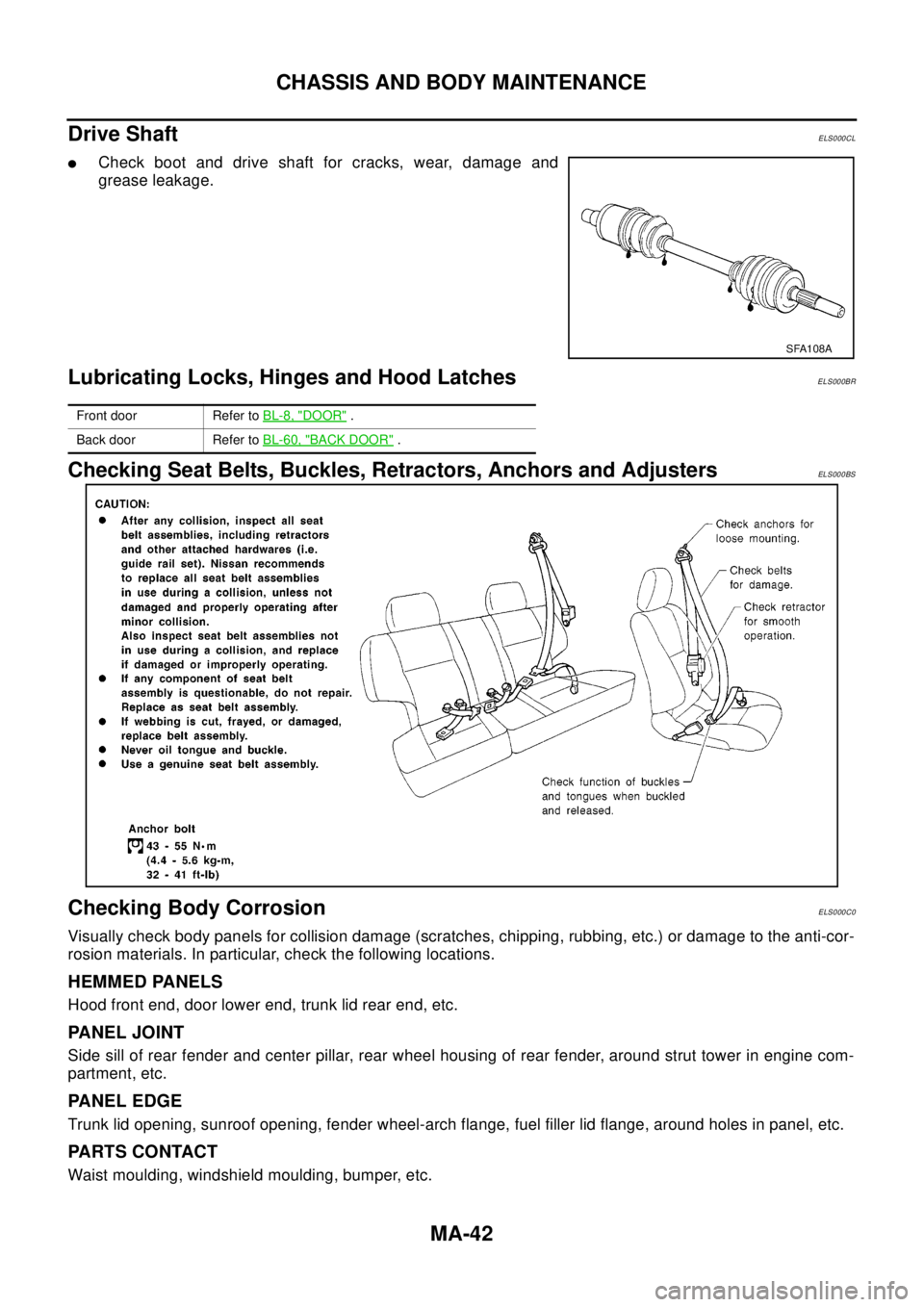
Drive Shaft
ELS000CL
lCheck boot and drive shaft for cracks, wear, damage and
grease leakage.
Lubricating Locks, Hinges and Hood LatchesELS000BR
Checking Seat Belts, Buckles, Retractors, Anchors and AdjustersELS000BS
Checking Body CorrosionELS000C0
Visually check body panels for collision damage (scratches, chipping, rubbing, etc.) or damage to the anti-cor-
rosion materials. In particular, check the following locations.
HEMMED PANELS
Hood front end, door lower end, trunk lid rear end, etc.
PANEL JOINT
Side sill of rear fender and center pillar, rear wheel housing of rear fender, around strut tower in engine com-
partment, etc.
PANEL EDGE
Trunk lid opening, sunroof opening, fender wheel-arch flange, fuel filler lid flange, around holes in panel, etc.
PA R T S C O N TA C T
Waist moulding, windshield moulding, bumper, etc.
SFA108A
Front door Refer toBL-8, "DOOR".
Back door Refer toBL-60, "
BACK DOOR".
Page 2535 of 3066
CHASSIS AND BODY MAINTENANCE
MA-43
C
D
E
F
G
H
I
J
K
MA
B
MA
PROTECTORS
Damage or condition of mudguard, fender protector, chipping protector, etc.
ANTI-CORROSION MATERIALS
Damage or separation of anti-corrosion materials under the body.
DRAIN HOLES
Condition of drain holes at door and side sill. When repairing corroded areas, refer to the Corrosion Repair
Manual.
Page 2536 of 3066

MA-44
SERVICE DATA AND SPECIFICATIONS (SDS)
SERVICE DATA AND SPECIFICATIONS (SDS)
PFP:00030
Standard and LimitELS000BZ
BELT DEFLECTION AND TENSION (QR20DE)
SPARK PLUG (QR20DE)
Tensions of drive belts Auto-adjustment by auto tensioner
MakeNGK
Ty peStandard LFR5A-11
Hot LFR4A-11
Cold LFR6A-11
Plug gap mm(in) 1.0 - 1.1 (0.039 - 0.043)
Page 2537 of 3066
MT-1
MANUAL TRANSAXLE
C TRANSMISSION/TRANSAXLE
CONTENTS
D
E
F
G
H
I
J
K
L
M
SECTION
A
B
MT
MANUAL TRANSAXLE
PRECAUTIONS .......................................................... 3
Caution ..................................................................... 3
PREPARATION ........................................................... 4
Special Service Tools ............................................... 4
Commercial Service Tools ........................................ 6
NOISE, VIBRATION, AND HARSHNESS (NVH)
TROUBLESHOOTING ................................................ 8
NVH Troubleshooting Chart ..................................... 8
MANUAL TRANSAXLE ......................................... 8
DESCRIPTION ............................................................ 9
Cross-sectional View ................................................ 9
DOUBLE-CONE SYNCHRONIZER .................... 10
REVERSE GEAR NOISE PREVENTION FUNC-
TION (SYNCHRONIZING METHOD) ................. 10
M/T OIL ......................................................................11
Changing M/T Oil ....................................................11
DRAINING ............................................................11
FILLING ................................................................11
Checking M/T Oil .....................................................11
OIL LEAKAGE AND OIL LEVEL ..........................11
SIDE OIL SEAL ........................................................ 12
Removal and Installation ........................................ 12
REMOVAL ........................................................... 12
INSTALLATION ................................................... 12
POSITION SWITCH .................................................. 13
Checking ................................................................ 13
BACK-UP LAMP SWITCH .................................. 13
PARK/NEUTRAL POSITION SWITCH ............... 13
CONTROL LINKAGE ............................................... 14
Removal and Installation of Control Device and
Cable ...................................................................... 14
AIR BREATHER HOSE ............................................ 15
Removal and Installation ........................................ 15
TRANSAXLE ASSEMBLY ........................................ 16
Removal and Installation ........................................ 16
REMOVAL ........................................................... 16
INSTALLATION ................................................... 17
Component Parts (RS5F51A) ................................ 18CASE AND HOUSING COMPONENTS .............. 18
GEAR COMPONENTS ....................................... 19
SHIFT CONTROL COMPONENTS ..................... 21
FINAL DRIVE COMPONENTS ........................... 22
Component Parts (RS6F51A) ................................. 23
CASE AND HOUSING COMPONENTS .............. 23
GEAR COMPONENTS ....................................... 24
SHIFT CONTROL COMPONENTS ..................... 26
FINAL DRIVE COMPONENTS ........................... 27
Disassembly and Assembly (RS5F51A) ................. 27
DISASSEMBLY ................................................... 27
ASSEMBLY ......................................................... 30
Disassembly and Assembly (RS6F51A) ................. 35
DISASSEMBLY ................................................... 35
ASSEMBLY ......................................................... 39
Adjustment (RS5F51A) ........................................... 44
INPUTSHAFT END PLAY ................................... 44
DIFFERENTIAL SIDE BEARING PRELOAD ...... 45
MAINSHAFT END PLAY ..................................... 46
REVERSE IDLER GEAR END PLAY .................. 47
Adjustment (RS6F51A) ........................................... 48
INPUTSHAFT END PLAY ................................... 48
DIFFERENTIAL SIDE BEARING PRELOAD ...... 49
MAINSHAFT END PLAY ..................................... 51
REVERSE IDLER GEAR END PLAY .................. 52
INPUT SHAFT AND GEARS .................................... 53
Assembly and Disassembly (RS5F51A) ................. 53
DISASSEMBLY ................................................... 53
INSPECTION AFTER DISASSEMBLY ................ 54
ASSEMBLY ......................................................... 55
Assembly and Disassembly (RS6F51A) ................. 60
DISASSEMBLY ................................................... 60
INSPECTION AFTER DISASSEMBLY ................ 61
ASSEMBLY ......................................................... 62
MAINSHAFT AND GEARS ....................................... 67
Assembly and Disassembly (RS5F51A) ................. 67
DISASSEMBLY ................................................... 67
INSPECTION AFTER DISASSEMBLY ................ 68
Page 2538 of 3066

MT-2
ASSEMBLY ......................................................... 70
Assembly and Disassembly (RS6F51A) ................. 74
DISASSEMBLY ................................................... 74
INSPECTION AFTER DISASSEMBLY ................ 76
ASSEMBLY ......................................................... 77
REVERSE IDLER SHAFT AND GEARS .................. 83
Assembly and Disassembly (RS5F51A) ................. 83
DISASSEMBLY ................................................... 83
INSPECTION AFTER DISASSEMBLY ................ 83
ASSEMBLY ......................................................... 84
Assembly and Disassembly (RS6F51A) ................. 84
DISASSEMBLY ................................................... 84
INSPECTION AFTER DISASSEMBLY ................ 84
ASSEMBLY ......................................................... 85
FINAL DRIVE ............................................................ 86
Assembly and Disassembly (RS5F51A) ................. 86
PRE-INSPECTION .............................................. 86
DISASSEMBLY ................................................... 86
INSPECTION AFTER DISASSEMBLY ................ 87
ASSEMBLY ......................................................... 87
Assembly and Disassembly (RS6F51A) ................. 89
PRE-INSPECTION .............................................. 89
DISASSEMBLY ................................................... 90
INSPECTION AFTER DISASSEMBLY ................ 91
ASSEMBLY ......................................................... 91
SHIFT CONTROL ...................................................... 94
Inspection (RS5F51A) ............................................ 94
SHIFT FORK ....................................................... 94
Inspection (RS6F51A) ............................................ 95
SHIFT FORK ....................................................... 95SERVICE DATA AND SPECIFICATIONS (SDS) ......96
General Specifications ............................................96
TRANSAXLE ........................................................96
FINAL GEAR ........................................................97
Gear End Play .........................................................97
Clearance Between Baulk Ring and Gear ..............97
3RD,4TH,5TH,6TH & REVERSE BAULK RING... 97
1ST AND 2ND DOUBLE BAULK RING ...............97
Available Snap Rings ..............................................98
INPUT SHAFT SPACER ......................................98
5TH MAIN GEAR .................................................98
Available C-rings .....................................................98
MAINSHAFT C-RING ..........................................98
Available Thrust Washer .........................................98
INPUT SHAFT THRUST WASHER .....................98
DIFFERENTIALSIDE GEAR THRUST WASHER
...99
Available Adjusting Shims .......................................99
MAINSHAFT ADJUSTING SHIM .........................99
INPUT SAFT REAR BEARING ADJUSTING
SHIM ....................................................................99
MAINSAFT REAR BEARING ADJUSTING SHIM.100
REVERASE IDLER GEAR ADJUSTING SHIM . 100
6TH MAIN GEAR ADJUSTING SHIM ................ 100
Available Shims .................................................... 100
BEARING PRELOAD ......................................... 100
DIFFERENTIAL SIDE BEARING ADJUSTING
SHIM(S) ............................................................. 100
Page 2539 of 3066
PRECAUTIONS
MT-3
D
E
F
G
H
I
J
K
L
MA
B
MT
PRECAUTIONSPFP:00001
CautionECS001WO
lDo not reuse transaxle oil, once it has been drained.
lCheck oil level or replace oil with vehicle on level ground.
lDuring removal or installation, keep inside of transaxle clear of dust or dirt.
lCheck for the correct installation status prior to removal or disassembly. If mating marks are required, be
certain they do not interfere with the function of the parts they are applied to.
lIn principle, tighten bolts or nuts gradually in several steps working diagonally from inside to outside. If
tightening sequence is specified, observe it.
lBe careful not to damage sliding surfaces and mating surfaces.
Page 2540 of 3066
MT-4
PREPARATION
PREPARATION
PFP:00002
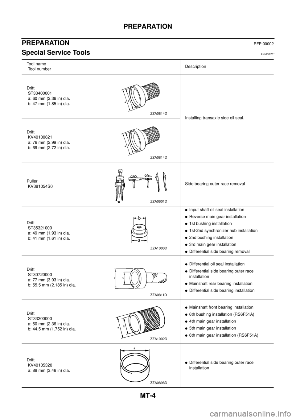
Special Service ToolsECS001WP
Tool name
Tool numberDescription
Drift
ST33400001
a: 60 mm (2.36 in) dia.
b: 47 mm (1.85 in) dia.
Installing transaxle side oil seal.
Drift
KV40100621
a: 76 mm (2.99 in) dia.
b: 69 mm (2.72 in) dia.
Puller
KV381054S0Side bearing outer race removal
Drift
ST35321000
a: 49 mm (1.93 in) dia.
b: 41 mm (1.61 in) dia.
lInput shaft oil seal installation
lReverse main gear installation
l1st bushing installation
l1st-2nd synchronizer hub installation
l2nd bushing installation
l3rd main gear installation
lDifferential side bearing removal
Drift
ST30720000
a: 77 mm (3.03 in) dia.
b: 55.5 mm (2.185 in) dia.
lDifferential oil seal installation
lDifferential side bearing outer race
installation
lMainshaft rear bearing installation
lDifferential side bearing installation
Drift
ST33200000
a: 60 mm (2.36 in) dia.
b: 44.5 mm (1.752 in) dia.
lMainshaft front bearing installation
l6th bushing installation (RS6F51A)
l4th main gear installation
l5th main gear installation
l6th main gear installation (RS6F51A)
Drift
KV40105320
a: 88 mm (3.46 in) dia.
lDifferential side bearing outer race
installation
ZZA0814D
ZZA0814D
ZZA0601D
ZZA1000D
ZZA0811D
ZZA1002D
ZZA0898D