NISSAN X-TRAIL 2003 Electronic Repair Manual
X-TRAIL 2003
NISSAN
NISSAN
https://www.carmanualsonline.info/img/5/57402/w960_57402-0.png
NISSAN X-TRAIL 2003 Electronic Repair Manual
Trending: water pump, headlamp, spare wheel, engine oil, fuse diagram, cruise control, trunk release
Page 2541 of 3066
PREPARATION
MT-5
D
E
F
G
H
I
J
K
L
MA
B
MT
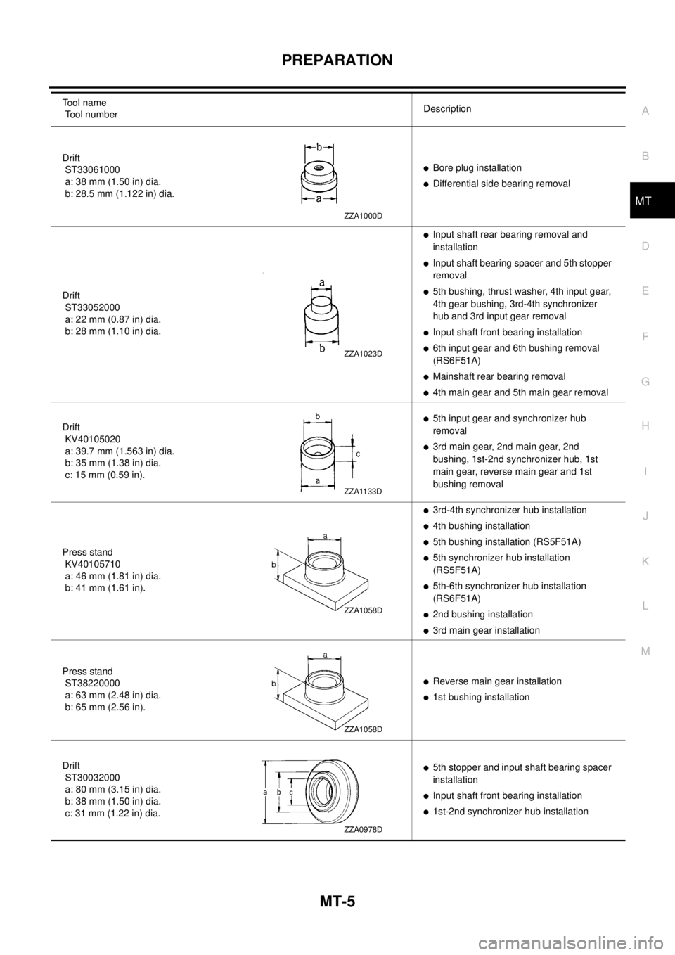
Drift
ST33061000
a: 38 mm (1.50 in) dia.
b: 28.5 mm (1.122 in) dia.lBore plug installation
lDifferential side bearing removal
Drift
ST33052000
a: 22 mm (0.87 in) dia.
b: 28 mm (1.10 in) dia.
lInput shaft rear bearing removal and
installation
lInput shaft bearing spacer and 5th stopper
removal
l5th bushing, thrust washer, 4th input gear,
4th gear bushing, 3rd-4th synchronizer
hub and 3rd input gear removal
lInput shaft front bearing installation
l6th input gear and 6th bushing removal
(RS6F51A)
lMainshaft rear bearing removal
l4th main gear and 5th main gear removal
Drift
KV40105020
a: 39.7 mm (1.563 in) dia.
b: 35 mm (1.38 in) dia.
c: 15 mm (0.59 in).
l5th input gear and synchronizer hub
removal
l3rd main gear, 2nd main gear, 2nd
bushing, 1st-2nd synchronizer hub, 1st
main gear, reverse main gear and 1st
bushing removal
Press stand
KV40105710
a: 46 mm (1.81 in) dia.
b: 41 mm (1.61 in).
l3rd-4th synchronizer hub installation
l4th bushing installation
l5th bushing installation (RS5F51A)
l5th synchronizer hub installation
(RS5F51A)
l5th-6th synchronizer hub installation
(RS6F51A)
l2nd bushing installation
l3rd main gear installation
Press stand
ST38220000
a: 63 mm (2.48 in) dia.
b: 65 mm (2.56 in).
lReverse main gear installation
l1st bushing installation
Drift
ST30032000
a: 80 mm (3.15 in) dia.
b: 38 mm (1.50 in) dia.
c: 31 mm (1.22 in) dia.
l5th stopper and input shaft bearing spacer
installation
lInput shaft front bearing installation
l1st-2nd synchronizer hub installation To o l n a m e
Tool numberDescription
ZZA1000D
ZZA1023D
ZZA1133D
ZZA1058D
ZZA1058D
ZZA0978D
Page 2542 of 3066
MT-6
PREPARATION
Commercial Service Tools
ECS004NA
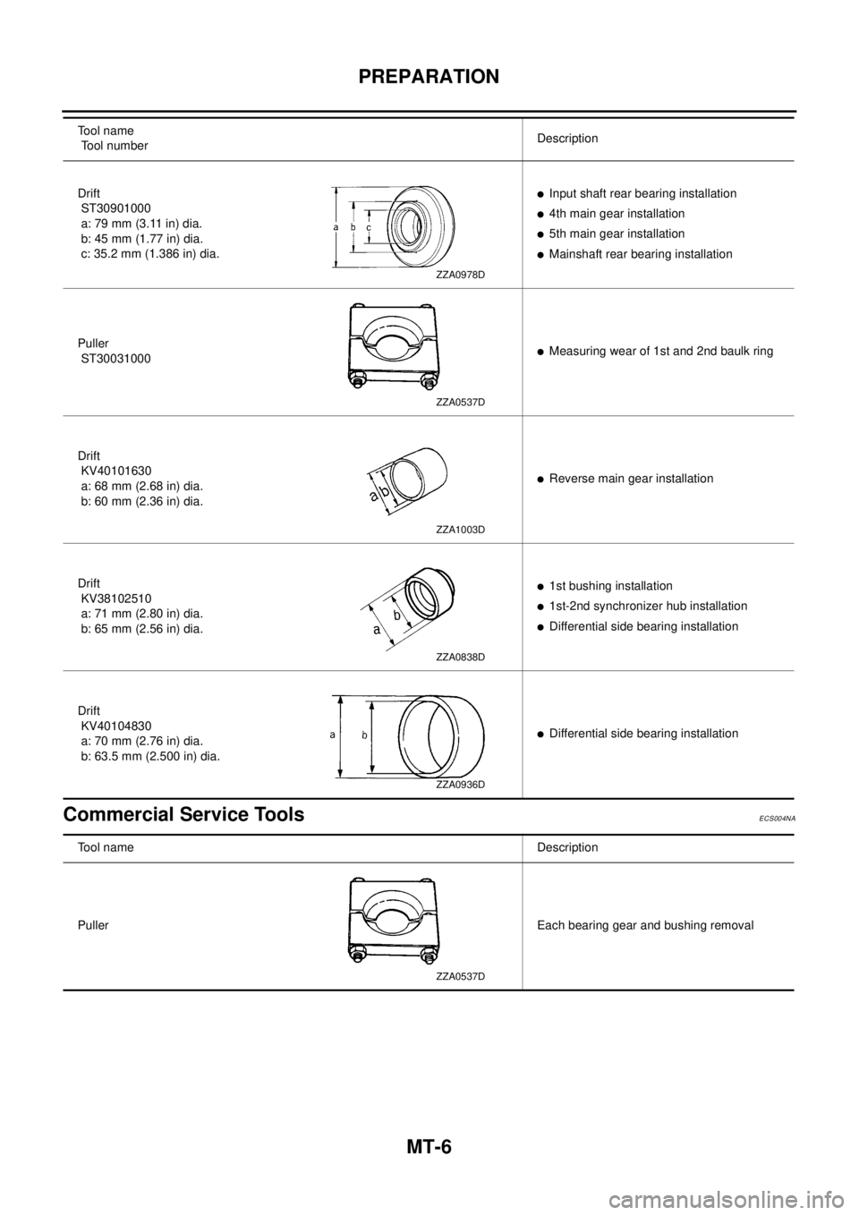
Drift
ST30901000
a: 79 mm (3.11 in) dia.
b: 45 mm (1.77 in) dia.
c: 35.2 mm (1.386 in) dia.lInput shaft rear bearing installation
l4th main gear installation
l5th main gear installation
lMainshaft rear bearing installation
Puller
ST30031000
lMeasuring wear of 1st and 2nd baulk ring
Drift
KV40101630
a: 68 mm (2.68 in) dia.
b: 60 mm (2.36 in) dia.
lReverse main gear installation
Drift
KV38102510
a: 71 mm (2.80 in) dia.
b: 65 mm (2.56 in) dia.
l1st bushing installation
l1st-2nd synchronizer hub installation
lDifferential side bearing installation
Drift
KV40104830
a: 70 mm (2.76 in) dia.
b: 63.5 mm (2.500 in) dia.
lDifferential side bearing installation Tool name
Tool numberDescription
ZZA0978D
ZZA0537D
ZZA1003D
ZZA0838D
ZZA0936D
Tool nameDescription
PullerEach bearing gear and bushing removal
ZZA0537D
Page 2543 of 3066
PREPARATION
MT-7
D
E
F
G
H
I
J
K
L
MA
B
MT
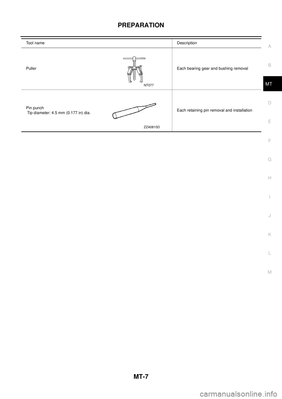
PullerEach bearing gear and bushing removal
Pin punch
Tip diameter: 4.5 mm (0.177 in) dia.Each retaining pin removal and installation To o l n a m eDescription
NT077
ZZA0815D
Page 2544 of 3066
MT-8
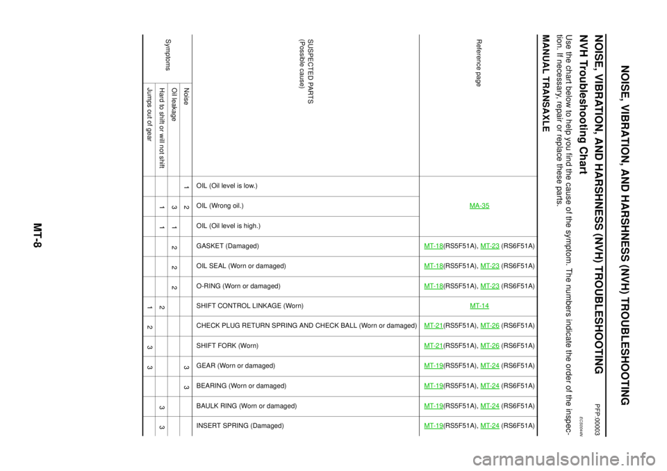
NOISE, VIBRATION, AND HARSHNESS (NVH) TROUBLESHOOTING
NOISE, VIBRATION, AND HARSHNESS (NVH) TROUBLESHOOTING
PFP:00003
NVH Troubleshooting ChartECS0044N
Use the chart below to help you find the cause of the symptom. The numbers indicate the order of the inspec-
tion. If necessary, repair or replace these parts.
MANUAL TRANSAXLE
Reference pageMA-35
MT-18
(RS5F51A),MT-23
(RS6F51A)
MT-18
(RS5F51A),MT-23
(RS6F51A)
MT-18
(RS5F51A),MT-23
(RS6F51A)
MT-14
MT-21
(RS5F51A),MT-26
(RS6F51A)
MT-21
(RS5F51A),MT-26
(RS6F51A)
MT-19
(RS5F51A),MT-24
(RS6F51A)
MT-19
(RS5F51A),MT-24
(RS6F51A)
MT-19
(RS5F51A),MT-24
(RS6F51A)
MT-19
(RS5F51A),MT-24
(RS6F51A)
SUSPECTED PARTS
(Possible cause)
OIL (Oil level is low.)
OIL(Wrongoil.)
OIL (Oil level is high.)
GASKET (Damaged)
OIL SEAL (Worn or damaged)
O-RING (Worn or damaged)
SHIFT CONTROL LINKAGE (Worn)
CHECK PLUG RETURN SPRING AND CHECK BALL (Worn or damaged)
SHIFT FORK (Worn)
GEAR (Worn or damaged)
BEARING (Worn or damaged)
BAULK RING (Worn or damaged)
INSERT SPRING (Damaged)
SymptomsNoise 1 2 3 3
Oilleakage 31222
Hard to shift or will not shift 1 1 2 3 3
Jumps out of gear 1 2 3 3
Page 2545 of 3066
DESCRIPTION
MT-9
D
E
F
G
H
I
J
K
L
MA
B
MT
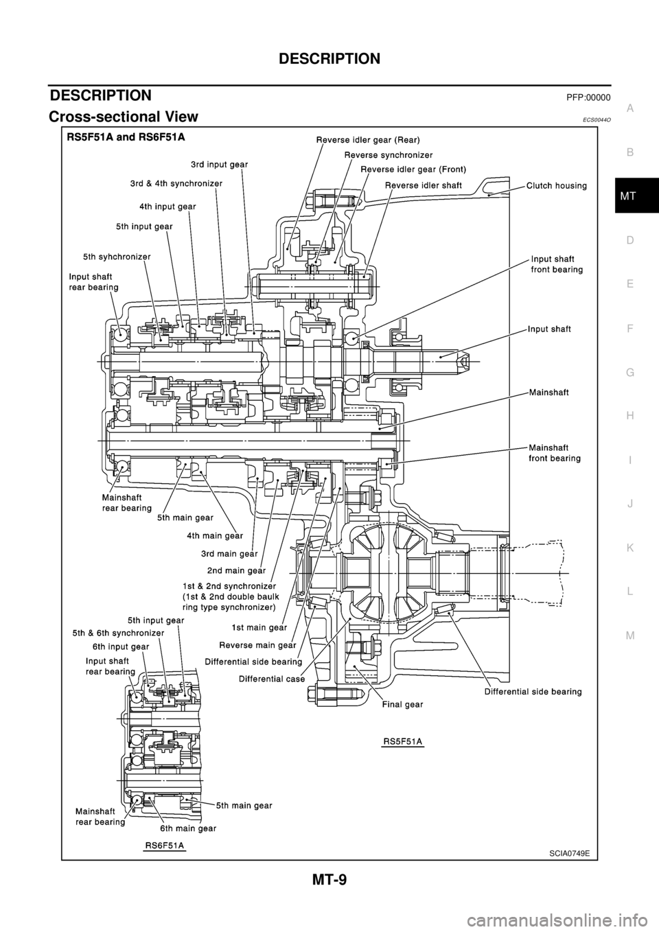
DESCRIPTIONPFP:00000
Cross-sectional ViewECS0044O
SCIA0749E
Page 2546 of 3066
MT-10
DESCRIPTION
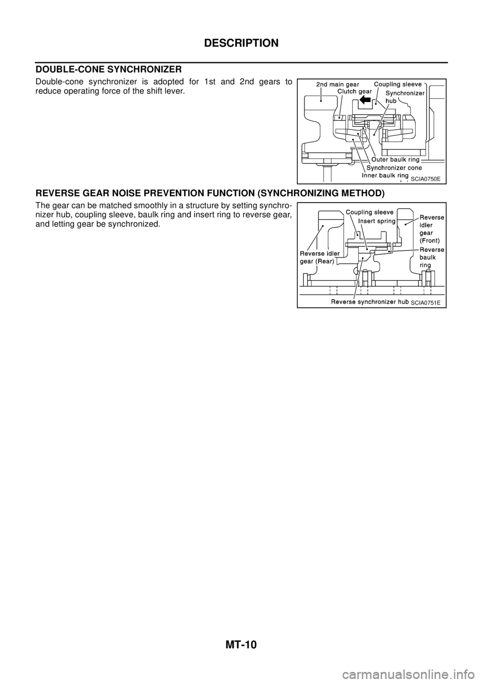
DOUBLE-CONE SYNCHRONIZER
Double-cone synchronizer is adopted for 1st and 2nd gears to
reduce operating force of the shift lever.
REVERSE GEAR NOISE PREVENTION FUNCTION (SYNCHRONIZING METHOD)
The gear can be matched smoothly in a structure by setting synchro-
nizer hub, coupling sleeve, baulk ring and insert ring to reverse gear,
and letting gear be synchronized.
SCIA0750E
SCIA0751E
Page 2547 of 3066
M/T OIL
MT-11
D
E
F
G
H
I
J
K
L
MA
B
MT
M/T OILPFP:KLD20
Changing M/T OilECS001WQ
DRAINING
1. Start the engine and let it run to warm up the transaxle.
2. Stop the engine. Remove drain plug and drain oil.
3. Set a gasket on the drain plug and install it to the transaxle.
CAUTION:
Do not reuse gasket.
FILLING
1. Remove filler plug. Fill with new oil until oil level reaches the specified limit near filler plug mounting hole.
2. After refilling oil, check oil level. Assemble gasket to filler plug, then install it to transaxle body.
CAUTION:
Do not reuse gasket.
Checking M/T OilECS001WR
OIL LEAKAGE AND OIL LEVEL
lCheck that oil is not leaking from transaxle or around it.
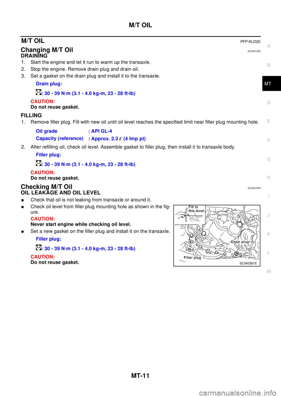
lCheck oil level from filler plug mounting hole as shown in the fig-
ure.
CAUTION:
Never start engine while checking oil level.
lSet a new gasket on the filler plug and install it on the transaxle.
CAUTION:
Do not reuse gasket.Drain plug:
: 30 - 39 N·m (3.1 - 4.0 kg-m, 23 - 28 ft-lb)
Oil grade : API GL-4
Capacity (reference)
: Approx. 2.3 (4 lmp pt)
Filler plug:
: 30 - 39 N·m (3.1 - 4.0 kg-m, 23 - 28 ft-lb)
Filler plug:
: 30 - 39 N·m (3.1 - 4.0 kg-m, 23 - 28 ft-lb)
SCIA0361E
Page 2548 of 3066
MT-12
SIDE OIL SEAL
SIDE OIL SEAL
PFP:32113
Removal and InstallationECS001WS
REMOVAL
lClutch housing side oil seal used on 4WD vehicles is attached to the transfer. Be sure to replace it
when transfer is removed.
1. Remove the driveshaft from the transaxle.
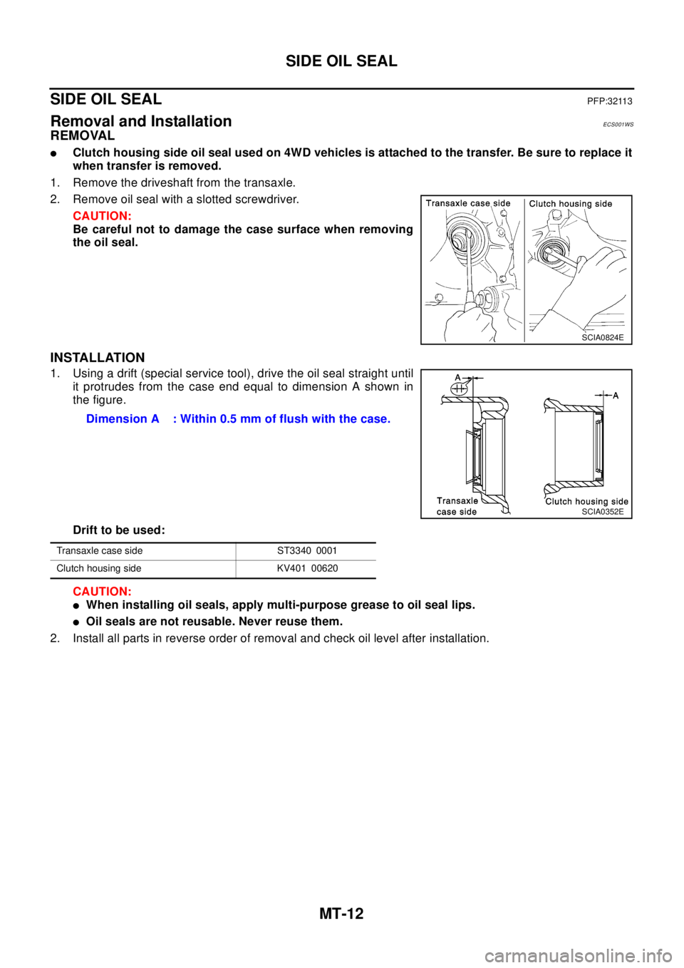
2. Remove oil seal with a slotted screwdriver.
CAUTION:
Be careful not to damage the case surface when removing
the oil seal.
INSTALLATION
1. Using a drift (special service tool), drive the oil seal straight until
it protrudes from the case end equal to dimension A shown in
the figure.
Drift to be used:
CAUTION:
lWhen installing oil seals, apply multi-purpose grease to oil seal lips.
lOil seals are not reusable. Never reuse them.
2. Install all parts in reverse order of removal and check oil level after installation.
SCIA0824E
Dimension A : Within 0.5 mm of flush with the case.
SCIA0352E
Transaxle case side ST3340 0001
Clutch housing side KV401 00620
Page 2549 of 3066
POSITION SWITCH
MT-13
D
E
F
G
H
I
J
K
L
MA
B
MT
POSITION SWITCHPFP:32005
CheckingECS001WT
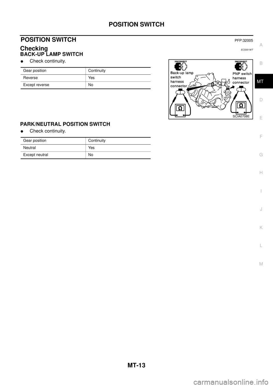
BACK-UP LAMP SWITCH
lCheck continuity.
PARK/NEUTRAL POSITION SWITCH
lCheck continuity.
Gear position Continuity
Reverse Yes
Except reverse No
SCIA0708E
Gear position Continuity
Neutral Yes
Except neutral No
Page 2550 of 3066
MT-14
CONTROL LINKAGE
CONTROL LINKAGE
PFP:34103
Removal and Installation of Control Device and CableECS001WU
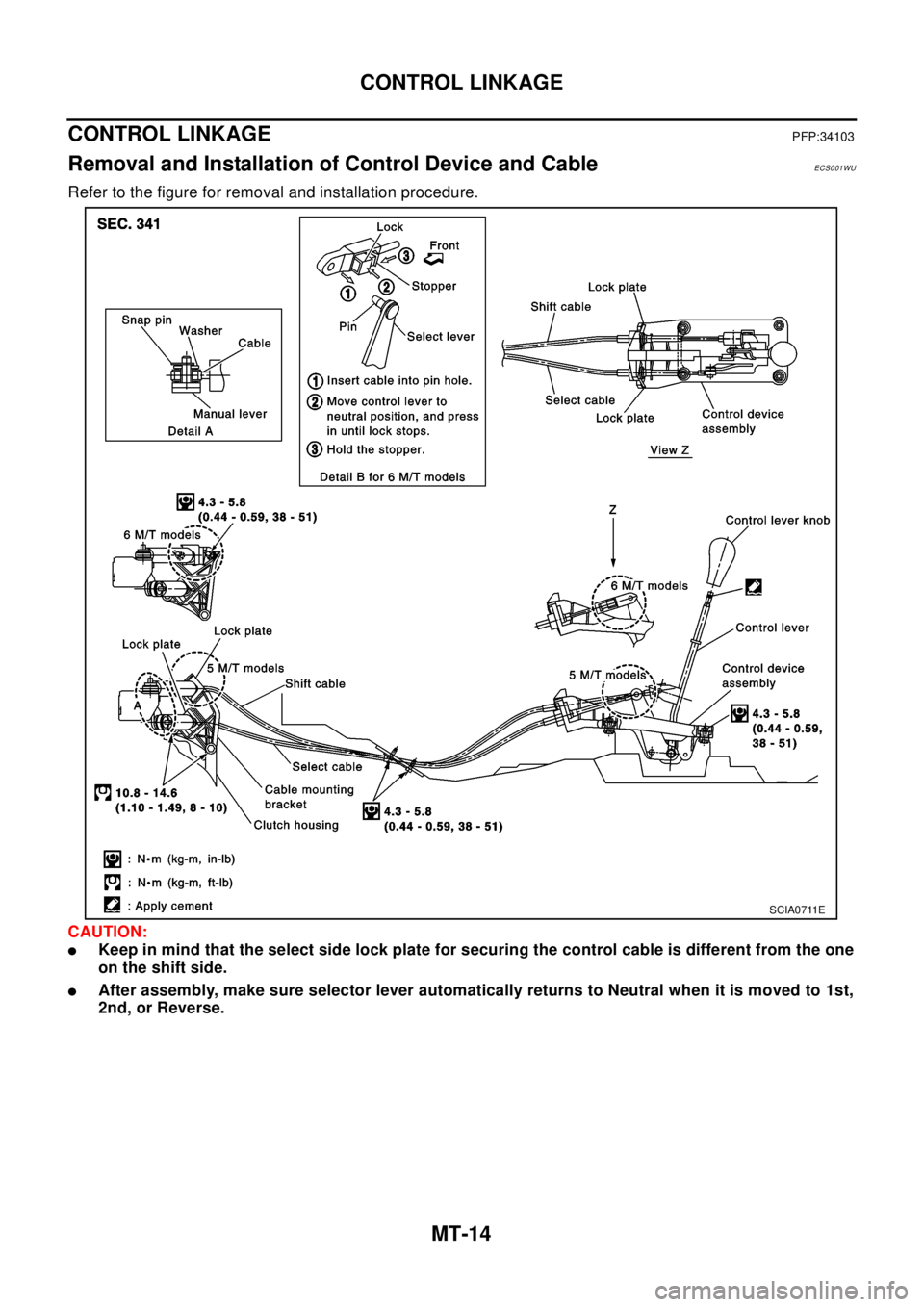
Refer to the figure for removal and installation procedure.
CAUTION:
lKeep in mind that the select side lock plate for securing the control cable is different from the one
on the shift side.
lAfter assembly, make sure selector lever automatically returns to Neutral when it is moved to 1st,
2nd, or Reverse.
SCIA0711E
Trending: weight, key battery, wheelbase, radio, cooling, transmission oil, service

