air filter NISSAN X-TRAIL 2003 Electronic Owner's Manual
[x] Cancel search | Manufacturer: NISSAN, Model Year: 2003, Model line: X-TRAIL, Model: NISSAN X-TRAIL 2003Pages: 3066, PDF Size: 51.47 MB
Page 500 of 3066
![NISSAN X-TRAIL 2003 Electronic Owners Manual AT-494
[ALL]
REPAIR FOR COMPONENT PARTS
ASSEMBLY
1. Install upper, inter and lower body.
a. Place oil circuit of upper body face up. Install steel balls in their
proper positions.
b. Install upper sep NISSAN X-TRAIL 2003 Electronic Owners Manual AT-494
[ALL]
REPAIR FOR COMPONENT PARTS
ASSEMBLY
1. Install upper, inter and lower body.
a. Place oil circuit of upper body face up. Install steel balls in their
proper positions.
b. Install upper sep](/img/5/57402/w960_57402-499.png)
AT-494
[ALL]
REPAIR FOR COMPONENT PARTS
ASSEMBLY
1. Install upper, inter and lower body.
a. Place oil circuit of upper body face up. Install steel balls in their
proper positions.
b. Install upper separating gasket, upper inter separating gasket
and upper separating plate in order shown in illustration.
c. Install reamer boltsffrom bottom of upper body. Using reamer
bolts as guides, install separating plate and gaskets as a set.
d. Install pilot filter.
SAT771J
SAT072F
SAT073FA
SAT074F
Page 581 of 3066
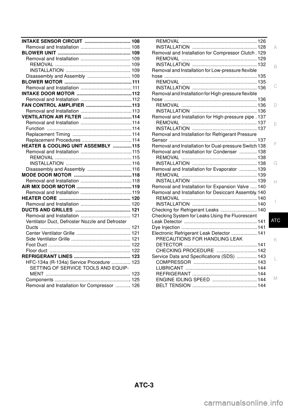
ATC-3
C
D
E
F
G
H
I
K
L
MA
B
AT C INTAKE SENSOR CIRCUIT ................................... 108
Removal and Installation ...................................... 108
BLOWER UNIT ....................................................... 109
Removal and Installation ...................................... 109
REMOVAL ......................................................... 109
INSTALLATION ................................................. 109
Disassembly and Assembly ................................. 109
BLOWER MOTOR ................................................... 111
Removal and Installation ...................................... . 111
INTAKE DOOR MOTOR .......................................... 112
Removal and Installation ....................................... 112
FAN CONTROL AMPLIFIER ................................... 113
Removal and Installation ....................................... 113
VENTILATION AIR FILTER ..................................... 114
Removal and Installation ....................................... 114
Function ................................................................ 114
Replacement Timing ............................................. 114
Replacement Procedures ...................................... 114
HEATER & COOLING UNIT ASSEMBLY ............... 115
Removal and Installation ....................................... 115
REMOVAL .......................................................... 115
INSTALLATION .................................................. 116
Disassembly and Assembly .................................. 116
MODE DOOR MOTOR ............................................ 118
Removal and Installation ....................................... 118
AIR MIX DOOR MOTOR .......................................... 119
Removal and Installation ....................................... 119
HEATER CORE ...................................................... 120
Removal and Installation ...................................... 120
DUCTS AND GRILLES .......................................... 121
Removal and Installation ...................................... 121
Ventilator Duct, Defroster Nozzle and Defroster
Ducts .................................................................... 121
Center Ventilator Grille ......................................... 121
Side Ventilator Grille ............................................. 121
Foot Duct .............................................................. 122
Floor duct ............................................................. 122
REFRIGERANT LINES ........................................... 123
HFC-134a (R-134a) Service Procedure ............... 123
SETTING OF SERVICE TOOLS AND EQUIP-
MENT ................................................................ 123
Components ......................................................... 125
Removal and Installation for Compressor ............ 126REMOVAL .........................................................126
INSTALLATION .................................................128
Removal and Installation for Compressor Clutch . 129
REMOVAL .........................................................129
INSTALLATION .................................................132
Removal and Installation for Low-pressure flexible
hose ......................................................................135
REMOVAL .........................................................135
INSTALLATION .................................................136
Removal and Installation for High-pressure flexible
hose ......................................................................136
REMOVAL .........................................................136
INSTALLATION .................................................136
Removal and Installation for High-pressure pipe ..137
REMOVAL .........................................................137
INSTALLATION .................................................137
Removal and Installation for Refrigerant Pressure
Sensor ..................................................................137
Removal and Installation for Dual-pressure Switch.138
Removal and Installation for Condenser ..............138
REMOVAL .........................................................138
INSTALLATION .................................................138
Removal and Installation for Evaporator ..............139
REMOVAL .........................................................139
INSTALLATION .................................................139
Removal and Installation for Expansion Valve ......140
Removal and Installation for Desiccant Assembly. 140
REMOVAL .........................................................140
INSTALLATION .................................................140
Checking for Refrigerant Leaks ............................140
Checking System for Leaks Using the Fluorescent
Leak Detector .......................................................141
Dye Injection .........................................................141
Electronic Refrigerant Leak Detector ....................141
PRECAUTIONS FOR HANDLING LEAK
DETECTOR .......................................................141
CHECKING PROCEDURE ...............................142
Service Data and Specifications (SDS) ................143
COMPRESSOR ................................................143
LUBRICANT ......................................................144
REFRIGERANT .................................................144
ENGINE IDLING SPEED ..................................144
BELT TENSION .................................................144
Page 692 of 3066
ATC-114
VENTILATION AIR FILTER
VENTILATION AIR FILTER
PFP:27277
Removal and InstallationEJS000UP
FunctionEJS000UQ
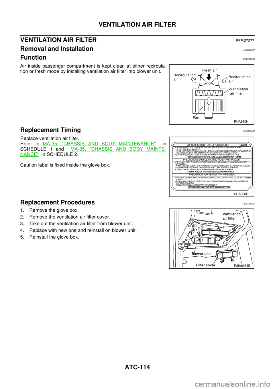
Air inside passenger compartment is kept clean at either recircula-
tion or fresh mode by installing ventilation air filter into blower unit.
Replacement TimingEJ S00 0UR
Replace ventilation air filter.
Refer toMA-35, "
CHASSIS AND BODY MAINTENANCE"in
SCHEDULE 1 andMA-35, "
CHASSIS AND BODY MAINTE-
NANCE"in SCHEDULE 2.
Caution label is fixed inside the glove box.
Replacement ProceduresEJS000US
1. Remove the glove box.
2. Remove the ventilation air filter cover.
3. Take out the ventilation air filter from blower unit.
4. Replace with new one and reinstall on blower unit.
5. Reinstall the glove box.
RHA680H
SHA868E
RJIA0058E
Page 718 of 3066
ATC-140
REFRIGERANT LINES
Removal and Installation for Expansion Valve
EJS000VH
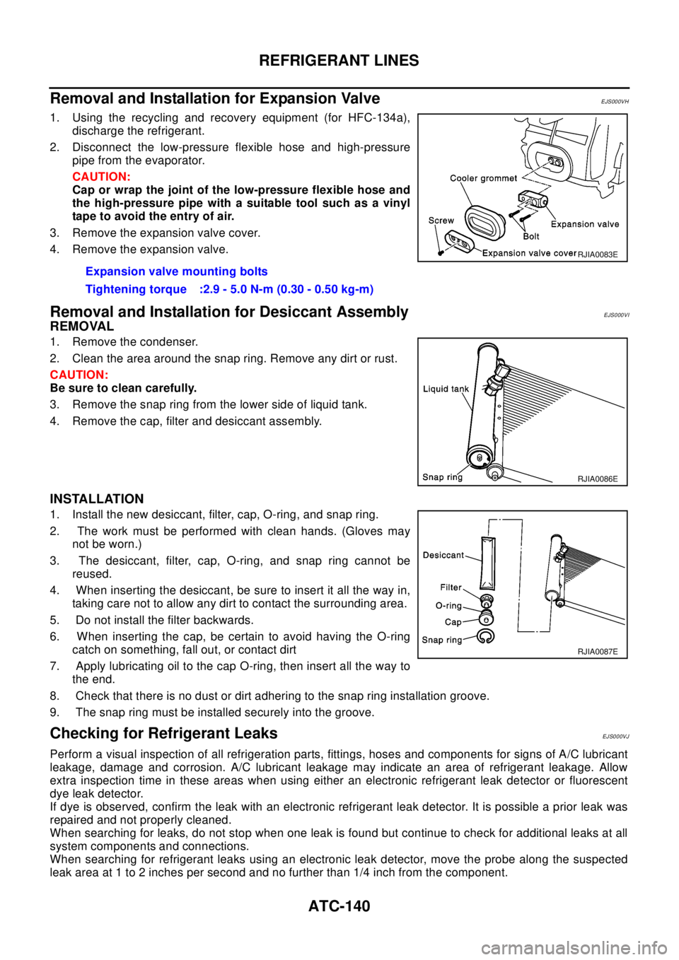
1. Using the recycling and recovery equipment (for HFC-134a),
discharge the refrigerant.
2. Disconnect the low-pressure flexible hose and high-pressure
pipe from the evaporator.
CAUTION:
Cap or wrap the joint of the low-pressure flexible hose and
the high-pressure pipe with a suitable tool such as a vinyl
tape to avoid the entry of air.
3. Remove the expansion valve cover.
4. Remove the expansion valve.
Removal and Installation for Desiccant AssemblyEJS000VI
REMOVAL
1. Remove the condenser.
2. Clean the area around the snap ring. Remove any dirt or rust.
CAUTION:
Be sure to clean carefully.
3. Remove the snap ring from the lower side of liquid tank.
4. Remove the cap, filter and desiccant assembly.
INSTALLATION
1. Install the new desiccant, filter, cap, O-ring, and snap ring.
2. The work must be performed with clean hands. (Gloves may
not be worn.)
3. The desiccant, filter, cap, O-ring, and snap ring cannot be
reused.
4. When inserting the desiccant, be sure to insert it all the way in,
taking care not to allow any dirt to contact the surrounding area.
5. Do not install the filter backwards.
6. When inserting the cap, be certain to avoid having the O-ring
catch on something, fall out, or contact dirt
7. Apply lubricating oil to the cap O-ring, then insert all the way to
the end.
8. Check that there is no dust or dirt adhering to the snap ring installation groove.
9. The snap ring must be installed securely into the groove.
Checking for Refrigerant LeaksEJS000VJ
Perform a visual inspection of all refrigeration parts, fittings, hoses and components for signs of A/C lubricant
leakage, damage and corrosion. A/C lubricant leakage may indicate an area of refrigerant leakage. Allow
extra inspection time in these areas when using either an electronic refrigerant leak detector or fluorescent
dye leak detector.
If dye is observed, confirm the leak with an electronic refrigerant leak detector. It is possible a prior leak was
repaired and not properly cleaned.
When searching for leaks, do not stop when one leak is found but continue to check for additional leaks at all
system components and connections.
When searching for refrigerant leaks using an electronic leak detector, move the probe along the suspected
leak area at 1 to 2 inches per second and no further than 1/4 inch from the component.Expansion valve mounting bolts
Tightening torque :2.9 - 5.0 N-m (0.30 - 0.50 kg-m)
RJIA0083E
RJIA0086E
RJIA0087E
Page 1072 of 3066
DI-18
COMBINATION METERS (LHD MODELS)
The Fuel Gauge Does Not Move to F-position.
EKS002ZK
1.QUESTIONNAIRE 1
Does it take a long time for the pointer to move to F-position?
YES?
YES >> GO TO 2.
NO >> GO TO 3.
2.QUESTIONNAIRE 2
Was the vehicle fueled with the ignition switch ON?
YES?
YES >> Be sure to fuel the vehicle with the ignition switch OFF. Otherwise it will take a long time to move
to F-position because of the characteristic of the fuel gauge.
NO >> GO TO 3.
3.QUESTIONNAIRE 3
Is the floor or the vehicle inclined?
YES?
YES >> It may not be filled fully.
NO >> GO TO 4.
4.QUESTIONNAIRE 4
During driving, does the fuel gauge pointer move gradually toward E-position?
YES?
YES >> Check the components. Refer toDI-19, "Electrical Components Inspection".
NO >> The float arm may interfere or bind with any of the components in the fuel tank.
The Fuel Gauge Does Not Work.EKS002ZL
1.HARNESS CONNECTOR INSPECTION
1. Turn the ignition switch OFF.
2. Check combination meter, fuel level sensor unit, sub fuel level sensor unit and terminals (meter-side,
module-side, and harness-side) for poor connection and bend.
OK or NG
OK >> GO TO 2.
NG >> Repair connector.
2.CHECK INSTALLATION CONDITION
Check fuel level sensor unit or sub fuel level sensor unit installation (refer toFL-4, "
FUEL LEVEL SENSOR
UNIT, FUEL FILTER AND FUEL PUMP ASSEMBLY"for QR engine models orFL-17, "FUEL LEVEL SEN-
SOR UNIT"for YD engine models, and check whether the float arm interferes or binds with any components
inside the arm.
OK or NG
OK >> Fuel level sensor unit is OK.
NG >> Check fuel level sensor unit or sub fuel level sensor unit. Refer toDI-19, "
Electrical Components
Inspection".
Page 1090 of 3066
DI-36
COMBINATION METERS (RHD MODELS)
The Fuel Gauge Does Not Move to F-position.
EKS0030V
1.QUESTIONNAIRE 1
Does it take a long time for the pointer to move to F-position?
YES?
YES >> GO TO 2.
NO >> GO TO 3.
2.QUESTIONNAIRE 2
Was the vehicle fueled with the ignition switch ON?
YES ?
YES >> Be sure to fuel the vehicle with the ignition switch OFF. Otherwise it will take a long time to move
to F-position because of the characteristic of the fuel gauge.
NO >> GO TO 3.
3.QUESTIONNAIRE 3
Is the floor or the vehicle inclined?
YES?
YES >> It may not be filled fully.
NO >> GO TO 4.
4.QUESTIONNAIRE 4
During driving, does the fuel gauge pointer move gradually toward E-position?
YES ?
YES >> Check the components. Refer toDI-37, "Electrical Components Inspection".
NO >> The float arm may interfere or bind with any of the components in the fuel tank.
The Fuel Gauge Does Not Work.EKS0030W
1.HARNESS CONNECTOR INSPECTION
1. Turn the ignition switch OFF.
2. Check combination meter, fuel level sensor unit, sub fuel level sensor unit and terminals (meter-side,
module-side, and harness-side) for poor connection and bend.
OK or NG
OK >> GO TO 2.
NG >> Repair connector.
2.CHECK INSTALLATION CONDITION
Check fuel level sensor unit or sub fuel level sensor unit installation (refer toFL-4, "
FUEL LEVEL SENSOR
UNIT, FUEL FILTER AND FUEL PUMP ASSEMBLY"for QR engine models orFL-17, "FUEL LEVEL SEN-
SOR UNIT"for YD engine models, and check whether the float arm interferes or binds with any components
inside the arm.
OK or NG
OK >> Fuel level sensor unit is OK.
NG >> Check fuel level sensor unit or sub fuel level sensor unit. Refer toDI-37, "
Electrical Components
Inspection".
Page 1123 of 3066
EC-9
C
D
E
F
G
H
I
J
K
L
M
ECA ENGINE CONTROL SYSTEM ................................ 659
System Diagram ................................................... 659
System Chart ....................................................... 660
Fuel Injection Control System .............................. 660
Fuel Injection Timing Control System ................... 662
Air Conditioning Cut Control ................................. 662
Fuel Cut Control (At No Load & High Engine Speed). 662
Crankcase Ventilation System ............................. 663
BASIC SERVICE PROCEDURE ............................ 664
Fuel Filter ............................................................. 664
Accelerator Pedal Released Position Learning .... 664
Fuel Pressure Relief Valve ................................... 665
ON BOARD DIAGNOSTIC (OBD) SYSTEM .......... 666
DTC and MI Detection Logic ................................ 666
Diagnostic Trouble Code (DTC) ........................... 666
NATS (Nissan Anti-theft System) ......................... 666
Malfunction Indicator (MI) ..................................... 667
TROUBLE DIAGNOSIS .......................................... 669
Trouble Diagnosis Introduction ............................. 669
Basic Inspection ................................................... 672
Symptom Matrix Chart ......................................... 676
Engine Control Component Parts Location .......... 680
Circuit Diagram .................................................... 683
ECM Harness Connector Terminal Layout ........... 685
ECM Terminals And Reference Value .................. 685
CONSULT-II Function .......................................... 691
CONSULT-II Reference Value in Data Monitor Mode
. 696
Major Sensor Reference Graph in Data Monitor
Mode .................................................................... 698
TROUBLE DIAGNOSIS FOR INTERMITTENT INCI-
DENT ...................................................................... 699
Description ........................................................... 699
Diagnostic Procedure ........................................... 699
POWER SUPPLY CIRCUIT FOR ECM .................. 700
ECM Terminals and Reference Value .................. 700
Wiring Diagram .................................................... 701
Diagnostic Procedure ........................................... 702
Component Inspection ......................................... 705
DTCP0100MASSAIRFLOWSENSOR(MAFS).. 706
Component Description ........................................ 706
CONSULT-II Reference Value in Data Monitor Mode
. 706
ECM Terminals and Reference Value .................. 706
On Board Diagnosis Logic ................................... 707
DTC Confirmation Procedure ............................... 707
Wiring Diagram .................................................... 708
Diagnostic Procedure ........................................... 709
Component Inspection ......................................... 710
Removal and Installation ...................................... 710
DTC P0115 ENGINE COOLANT TEMPERATURE
(ECT) SENSOR (CIRCUIT) ...................................... 711
Description ............................................................ 711
On Board Diagnosis Logic .................................... 711
DTC Confirmation Procedure ................................ 711
Wiring Diagram .................................................... 712
Diagnostic Procedure ........................................... 713Component Inspection ..........................................714
Removal and Installation ......................................714
DTC P0120 ACCELERATOR PEDAL POSITION
SENSOR .................................................................715
Description ............................................................715
CONSULT-II Reference Value in Data Monitor Mode
.715
ECM Terminals and Reference Value ...................715
On Board Diagnosis Logic ....................................716
DTC Confirmation Procedure ...............................716
Wiring Diagram .....................................................717
Diagnostic Procedure ...........................................718
Component Inspection ..........................................721
Removal and Installation ......................................722
DTC P0190 COMMON RAIL FUEL PRESSURE
SENSOR .................................................................723
Description ............................................................723
CONSULT-II Reference Value in Data Monitor Mode
.723
ECM Terminals and Reference Value ...................723
On Board Diagnosis Logic ....................................723
DTC Confirmation Procedure ...............................723
Wiring Diagram .....................................................724
Diagnostic Procedure ...........................................725
Component Inspection ..........................................726
Removal and Installation ......................................726
DTC P0201 - P0204 FUEL INJECTOR ...................727
Description ............................................................727
CONSULT-II Reference Value in Data Monitor Mode
.727
ECM Terminals and Reference Value ...................727
On Board Diagnosis Logic ....................................728
DTC Confirmation Procedure ...............................729
Wiring Diagram .....................................................730
Diagnostic Procedure ...........................................732
Component Inspection ..........................................733
Removal and Installation ......................................733
DTC P0335 CRANKSHAFT POSISTION SENSOR
(TDC) .......................................................................734
Description ............................................................734
CONSULT-II Reference Value in Data Monitor Mode
.734
ECM Terminals and Reference Value ...................734
On Board Diagnosis Logic ....................................735
DTC Confirmation Procedure ...............................735
Wiring Diagram .....................................................736
Diagnostic Procedure ...........................................737
Component Inspection ..........................................737
Removal and Installation ......................................738
DTC P0340 CAMSHAFT POSITION SENSOR ......739
Description ............................................................739
ECM Terminals and Reference Value ...................739
On Board Diagnosis Logic ....................................739
DTC Confirmation Procedure ...............................739
Wiring Diagram .....................................................741
Diagnostic Procedure ...........................................742
Component Inspection ..........................................742
Removal and Installation ......................................743
Page 1149 of 3066
![NISSAN X-TRAIL 2003 Electronic Owners Manual BASIC SERVICE PROCEDURE
EC-35
[QR (WITH EURO-OBD)]
C
D
E
F
G
H
I
J
K
L
MA
EC
lTo avoid unnecessary force or tension to hose, use moderately long fuel hose for fuel pressure check.
lDo not use the fuel NISSAN X-TRAIL 2003 Electronic Owners Manual BASIC SERVICE PROCEDURE
EC-35
[QR (WITH EURO-OBD)]
C
D
E
F
G
H
I
J
K
L
MA
EC
lTo avoid unnecessary force or tension to hose, use moderately long fuel hose for fuel pressure check.
lDo not use the fuel](/img/5/57402/w960_57402-1148.png)
BASIC SERVICE PROCEDURE
EC-35
[QR (WITH EURO-OBD)]
C
D
E
F
G
H
I
J
K
L
MA
EC
lTo avoid unnecessary force or tension to hose, use moderately long fuel hose for fuel pressure check.
lDo not use the fuel hose for checking fuel pressure with damage or cracks on it.
lUse Pressure Gauge to check fuel pressure.
3. Remove fuel hose. Refer toEM-17, "
INTAKE MANIFOLD".
lDo not twist or kink fuel hose because it is plastic hose.
lDo not remove fuel hose from quick connector.
lKeep the original fuel hose to be free from intrusion of dust or foreign substances with a suitable cover.
4. Install the fuel pressure gauge as shown in the figure.
lWipe off oil or dirt from hose insertion part using cloth moist-
ened with gasoline.
lApply proper amount of gasoline between top of the fuel tube
and No.1 spool.
lInsert fuel hose for fuel pressure check until it touches the
No.1 spool on fuel tube.
lUse NISSAN genuine hose clamp (part number: 16439
N4710 or 16439 40U00).
lWhen reconnecting fuel line, always use new clamps.
lWhen reconnecting fuel hose, check the original fuel hose for
damage and abnormality.
lUse a torque driver to tighten clamps.
lInstall hose clamp to the position within 1 - 2 mm (0.04 - 0.08
in).
lMake sure that clamp screw does not contact adjacent parts.
5. After connecting fuel hose for fuel pressure check, pull the hose
with a force of approximately 98 N (10 kg, 22 lb) to confirm fuel
tube does not come off.
6. Turn ignition switch "ON", and check for fuel leakage.
7. Start engine and check for fuel leakage.
8. Read the indication of fuel pressure gauge.
lDo not perform fuel pressure check with system operating. Fuel pressure gauge may indicate false
readings.
lDuring fuel pressure check, confirm for fuel leakage from fuel connection every 3 minutes.
9. If result is unsatisfactory, go to next step.
10. Check the following.
lFuel hoses and fuel tubes for clogging
lFuel filter for clogging
lFuel pump
lFuel pressure regulator for clogging
If OK, replace fuel pressure regulator.
If NG, repair or replace.Tightening torque: 1 - 1.5 N·m (0.1 - 0.15 kg-m,
9-13in-lb)
At idling:
Approximately 350 kPa (3.5 bar, 3.7 kg/cm
2,51psi)
PBIB0669E
PBIB0670E
Page 1185 of 3066
![NISSAN X-TRAIL 2003 Electronic Owners Manual TROUBLE DIAGNOSIS
EC-71
[QR (WITH EURO-OBD)]
C
D
E
F
G
H
I
J
K
L
MA
EC
Air Air duct
55555 5EM-15
Air cleanerEM-15
Air leakage from air duct
(Mass air flow sensor —electric
throttle control actuator) NISSAN X-TRAIL 2003 Electronic Owners Manual TROUBLE DIAGNOSIS
EC-71
[QR (WITH EURO-OBD)]
C
D
E
F
G
H
I
J
K
L
MA
EC
Air Air duct
55555 5EM-15
Air cleanerEM-15
Air leakage from air duct
(Mass air flow sensor —electric
throttle control actuator)](/img/5/57402/w960_57402-1184.png)
TROUBLE DIAGNOSIS
EC-71
[QR (WITH EURO-OBD)]
C
D
E
F
G
H
I
J
K
L
MA
EC
Air Air duct
55555 5EM-15
Air cleanerEM-15
Air leakage from air duct
(Mass air flow sensor —electric
throttle control actuator)
5555EM-15
Electric throttle control actuatorEM-17
Air leakage from intake manifold/
Collector/GasketEM-17
Cranking Battery
111111 11SC-3
Alternator circuitSC-12
Starter c irc uit 3SC-21
Signal plate 6EM-64
PNP switch
4MT-13or
AT- 1 3 5
Engine Cylinder head
55555 55 5EM-52
Cylinder head gasket 4 3
Cylinder block
66666 66 64
EM-64
Piston
Piston ring
Connecting rod
Bearing
Crankshaft
Va l v e
mecha-
nismTiming chain
55555 55 5EM-43
CamshaftEM-33
Intake valve
3EM-52
Exhaust valve
Exhaust Exhaust manifold/Tube/Muffler/
Gasket
55555 55 5EM-22
,EX-
2Three way catalyst
Lubrica-
tionOil pan/Oil strainer/Oil pump/Oil
filter/Oil gallery/Oil cooler
55555 55 52EM-24
,LU-
9,LU-10,
LU-13
Oil level (Low)/Filthy oilLU-7
SYMPTOM
Reference
page
HARD/NO START/RESTART (EXCP. HA)
ENGINE STALL
HESITATION/SURGING/FLAT SPOT
SPARK KNOCK/DETONATION
LACK OF POWER/POOR ACCELERATION
HIGH IDLE/LOW IDLE
ROUGH IDLE/HUNTING
IDLING VIBRATION
SLOW/NO RETURN TO IDLE
OVERHEATS/WATER TEMPERATURE HIGH
EXCESSIVE FUEL CONSUMPTION
EXCESSIVE OIL CONSUMPTION
BATTERY DEAD (UNDER CHARGE)
Warranty symptom code AA AB AC AD AE AF AG AH AJ AK AL AM HA
Page 1514 of 3066
![NISSAN X-TRAIL 2003 Electronic Owners Manual EC-400
[QR (WITHOUT EURO-OBD)]
BASIC SERVICE PROCEDURE
3. Remove fuel hose. Refer toEM-17, "INTAKE MANIFOLD".
lDo not twist or kink fuel hose because it is plastic hose.
lDo not remove fuel hose from NISSAN X-TRAIL 2003 Electronic Owners Manual EC-400
[QR (WITHOUT EURO-OBD)]
BASIC SERVICE PROCEDURE
3. Remove fuel hose. Refer toEM-17, "INTAKE MANIFOLD".
lDo not twist or kink fuel hose because it is plastic hose.
lDo not remove fuel hose from](/img/5/57402/w960_57402-1513.png)
EC-400
[QR (WITHOUT EURO-OBD)]
BASIC SERVICE PROCEDURE
3. Remove fuel hose. Refer toEM-17, "INTAKE MANIFOLD".
lDo not twist or kink fuel hose because it is plastic hose.
lDo not remove fuel hose from quick connector.
lKeep the original fuel hose to be free from intrusion of dust or foreign substances with a suitable cover.
4. Install the fuel pressure gauge as shown in the figure.
lWipe off oil or dirt from hose insertion part using cloth moist-
ened with gasoline.
lApply proper amount of gasoline between top of the fuel tube
and No.1 spool.
lInsert fuel hose for fuel pressure check until it touches the
No.1 spool on fuel tube.
lUse NISSAN genuine hose clamp (part number: 16439
N4710 or 16439 40U00).
lWhen reconnecting fuel line, always use new clamps.
lWhen reconnecting fuel hose, check the original fuel hose for
damage and abnormality.
lUse a torque driver to tighten clamps.
lInstall hose clamp to the position within 1 - 2 mm (0.04 - 0.08
in).
lMake sure that clamp screw does not contact adjacent parts.
5. After connecting fuel hose for fuel pressure check, pull the hose
with a force of approximately 98 N (10 kg, 22 lb) to confirm fuel
tube does not come off.
6. Turn ignition switch "ON", and check for fuel leakage.
7. Start engine and check for fuel leakage.
8. Read the indication of fuel pressure gauge.
lDo not perform fuel pressure check with system operating. Fuel pressure gauge may indicate false
readings.
lDuring fuel pressure check, confirm for fuel leakage from fuel connection every 3 minutes.
9. If result is unsatisfactory, go to next step.
10. Check the following.
lFuel hoses and fuel tubes for clogging
lFuel filter for clogging
lFuel pump
lFuel pressure regulator for clogging
If OK, replace fuel pressure regulator.
IfNG,repairorreplace.Tightening torque: 1 - 1.5 N·m (0.1 - 0.15 kg-m, 9 - 13
in-lb)
At idling: Approximately 350 kPa (3.5 bar, 3.7 kg/cm
2,51psi)
PBIB0669E
PBIB0670E