OPEL FRONTERA 1998 Workshop Manual
Manufacturer: OPEL, Model Year: 1998, Model line: FRONTERA, Model: OPEL FRONTERA 1998Pages: 6000, PDF Size: 97 MB
Page 5791 of 6000

7A–10 AUTOMATIC TRANSMISSION (AW30-40LE)
LOCATION OF CLUTCH, BRAKE, ONE-WAY CLUTCH AND SOLENOID
C07RY00006
EndOFCallout
Legend
C-0: Overdrive direct clutch
C-1: Forward clutch
C-2: Direct clutch
B-0: Overdrive brake
B-1: Second coast brake
B-2: Second brake
B-3: First and reverse brake
F-0: Overdrive one-way clutch
F-1: One-way clutch (No.1)
F-2: One-way clutch (No.2)
S-1: Shift solenoid S1
S-2: Shift solenoid S2
S-3: Lock-up solenoid SL
S-4: Pressure control solenoid STH
Page 5792 of 6000

AUTOMATIC TRANSMISSION (AW30-40LE) 7A–11
OPERATION OF CLUTCH, BRAKE AND ONE-WAY CLUTCH
:Operating :Free at coast down :Operating at Lock-up
(1*): Down-shift only in the L range and 2nd
gear - no up-shift.
(2*): Down-shift only in the L range and 3rd gear - no up-shift.
SPEED CHANGE AND LOCK-UP PATTERN
If you select a speed range and a lock-up pattern as shown below by specifying respective positions of transmission
shift lever, transfer shift lever and pattern select switch, the transmission control computer controls speed change and
lock-up operations based on the specified pattern in accordance with the degree of throttle opening and vehicle speed.
: The lock-up operation is available.
( ): Transmission is shifted at high speed to prevent overrun.
Shift lever
positionGear positionC-0C-1C-2B-0B-1B-2B-3F-0F-1F-2S-1S-2S-3
PParking
RReverse
NNeutral
D1st
2nd
3rd
O/D
21st
2nd
3rd
L1st
(1*) 2nd
(2*) 3rd
Pattern select sw.
positionTransmission shift position
D
2L
Overdrive OFF switch
OFF Overdrive OFF switch
ON
NORMAL
POWER1st
2nd 1st 2nd 1st2nd(3rd) 1st(2nd)(3rd)
WINTER 3rd fixed──
Page 5793 of 6000

7A–12 AUTOMATIC TRANSMISSION (AW30-40LE)
OVERDRIVE AND LOCK-UP OPERATING CONDITIONS
The overdrive and lock-up clutch operate if the following conditions are satisfied.
(1*):
If transmission oil temperature is more than 130C, lock-up is inhibit.
OverdriveLock-up clutch
Transmission shift positionD range (1*)
O/D OFF switchOFF (O/D OFF lamp OFF)—
Stop lamp switch—OFF
Throttle opening—Except fully closed
Vehicle speedAbout 49 km/h or more3rd: About 50 km/h or more
O/D: About 65 km/h or more
Page 5794 of 6000

AUTOMATIC TRANSMISSION (AW30-40LE) 7A–13
DIAGNOSIS
BASIC TROUBLESHOOTING
AW30-40LE transmission, called Electronic Controlled Transmission (ECT), differs from oil pressure control type
transmissions in that it is controlled by a microcomputer. Accordingly, its troubleshooting procedure differs also.
Before troubleshooting an ECT, first determine whether the problem is electrical or mechanical. To do this, just refer to
the basic troubleshooting flowchart provided below. If the cause is already known, using the basic troubleshooting
chart below along with the general troubleshooting char t on the following page should speed the procedure.
Page 5795 of 6000

7A–14 AUTOMATIC TRANSMISSION (AW30-40LE)
821RY00012
F07LV002
740RY00013
740RY00014
SELF-DIAGNOSIS
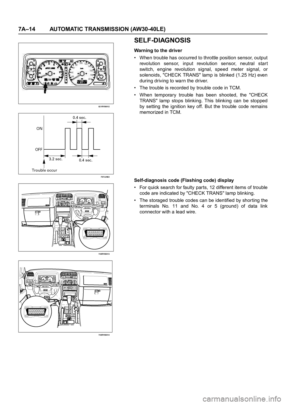
Warning to the driver
• When trouble has occurred to throttle position sensor, output
revolution sensor, input revolution sensor, neutral star t
switch, engine revolution signal, speed meter signal, or
solenoids, "CHECK TRANS" lamp is blinked (1.25 Hz) even
during driving to warn the driver.
• The trouble is recorded by trouble code in TCM.
• When temporary trouble has been shooted, the "CHECK
TRANS" lamp stops blinking. This blinking can be stopped
by setting the ignition key off. But the trouble code remains
memorized in TCM.
Self-diagnosis code (Flashing code) display
• For quick search for faulty parts, 12 different items of trouble
code are indicated by "CHECK TRANS" lamp blinking.
• The storaged trouble codes can be identified by shor ting the
terminals No. 11 and No. 4 or 5 (ground) of data link
connector with a lead wire.
Page 5796 of 6000

AUTOMATIC TRANSMISSION (AW30-40LE) 7A–15
F07LV001
Indication Method:
1.Terminals No. 11 are No. 4 or 5 (ground) of data link
connector are short circuited.
2. Turn the ignition key to the ON position.
3. In case there no trouble, normal code is indicated.
4. In case a plurality of trouble codes have occurred at a time,
each code is indicated three times in numerical order.
NOTE:
Power line runs through data link connector.
Be careful shorting with a lead wire, etc.
(The vehicle side of control module may be damaged.) For
identification of trouble code, connect Tech2 to data link
connector.
Clear of trouble code memory
1. Clear the trouble code memory using F1: Clear DTC
Information for Tech2.
2. After more than 1 second has elapsed after the ignition key
has been turned ON, short between No. 11 and No. 4 or 5
(ground) of data link connector. Then, after 1 second, but
within 6 seconds, discontinue shorting.
Page 5797 of 6000

7A–16 AUTOMATIC TRANSMISSION (AW30-40LE)
Flashing code
F07RY00016
Page 5798 of 6000

AUTOMATIC TRANSMISSION (AW30-40LE) 7A–17
DIAGNOSIS WITH TECH2
In this AW30-40LE transmission, troubleshooting can be
performed for electrical faults using the Tech2 scan tool.
If the CHECK TRANS lamp blinks, or if an electrical fault in the
transmission may probably exist, check trouble codes using the
Tech2 scan tool.
In the diagnostic procedures described in this manual, first
repair the faulty positions indicated by trouble code in the order
of numbers and then perform troubleshooting for the faulty
positions that are not indicated by trouble code. For correct
troubleshooting, it is necessary to first repair the trouble codes
of lower-order numbers, then to repair the trouble codes of
higher-order numbers in sequence.
How to Use This Manual:
Check trouble codes using the Tech2 scan tool.
If no codes are set:
•Refer to
F1: Data Display and identify the electrical faults
that are not indicated by trouble code.
If codes are set:
• Record all the codes displayed by the Tech2 and check if the
codes are intermittent (intermittent faults).
• Clear the codes.
• Drive the vehicle for a test to reproduce the faulty status.
• Check trouble codes again using the Tech2.
• If no code is displayed by test driving, the fault is intermittent.
In this case, refer to the cautions on intermittent conditions.
• If a code is present, refer to "DIAGNOSTIC TROUBLE
CODES (DTC) CHECK" for diagnosis.
• Because a code of high-order number may be set for the
reason that a code of low-order number has been set after
occurrence of a fault, perform repair work starting with a
lower-order number is ascending order.
Page 5799 of 6000

7A–18 AUTOMATIC TRANSMISSION (AW30-40LE)
901RW176
F07RW033
740RY00013
740RY00014
901RY00014
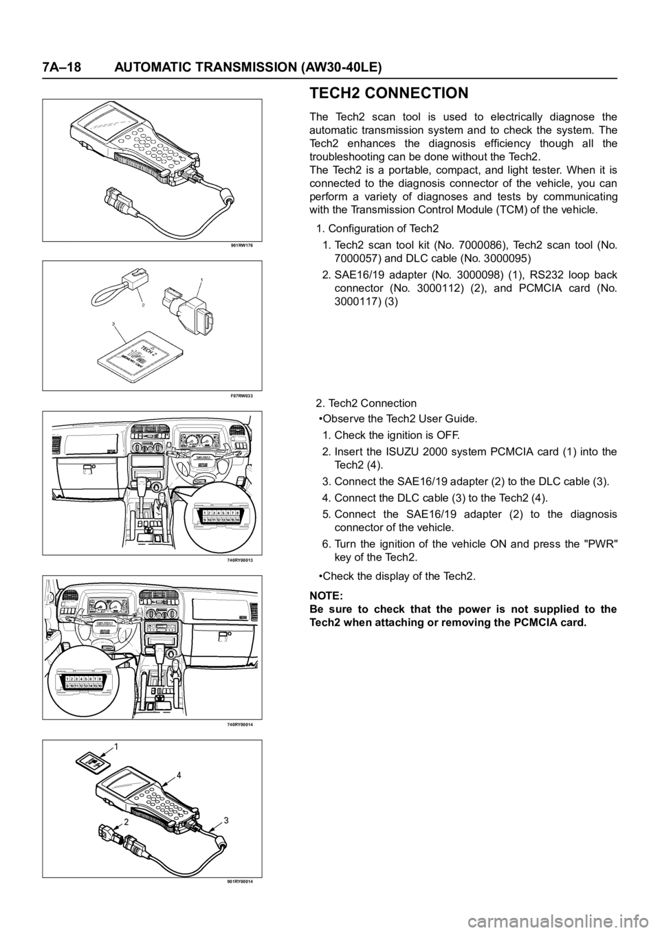
TECH2 CONNECTION
The Tech2 scan tool is used to electrically diagnose the
automatic transmission system and to check the system. The
Tech2 enhances the diagnosis efficiency though all the
troubleshooting can be done without the Tech2.
The Tech2 is a portable, compact, and light tester. When it is
connected to the diagnosis connector of the vehicle, you can
perform a variety of diagnoses and tests by communicating
with the Transmission Control Module (TCM) of the vehicle.
1. Configuration of Tech2
1. Tech2 scan tool kit (No. 7000086), Tech2 scan tool (No.
7000057) and DLC cable (No. 3000095)
2. SAE16/19 adapter (No. 3000098) (1), RS232 loop back
connector (No. 3000112) (2), and PCMCIA card (No.
3000117) (3)
2. Tech2 Connection
•Observe the Tech2 User Guide.
1. Check the ignition is OFF.
2. Inser t the ISUZU 2000 system PCMCIA card (1) into the
Te c h 2 ( 4 ) .
3. Connect the SAE16/19 adapter (2) to the DLC cable (3).
4. Connect the DLC cable (3) to the Tech2 (4).
5. Connect the SAE16/19 adapter (2) to the diagnosis
connector of the vehicle.
6. Turn the ignition of the vehicle ON and press the "PWR"
key of the Tech2.
•Check the display of the Tech2.
NOTE:
Be sure to check that the power is not supplied to the
Tech2 when attaching or removing the PCMCIA card.
Page 5800 of 6000

AUTOMATIC TRANSMISSION (AW30-40LE) 7A–19
TECH2 OPERATING FLOW CHART (START UP)
060RY00110