OPEL FRONTERA 1998 Workshop Manual
FRONTERA 1998
OPEL
OPEL
https://www.carmanualsonline.info/img/37/57409/w960_57409-0.png
OPEL FRONTERA 1998 Workshop Manual
Trending: catalytic converter, height adjustment, length, fuse box, spare wheel, pairing phone, fuse chart
Page 5761 of 6000
7A–72
AUTOMATIC TRANSMISSION (4L30–E)
3–4 Accumulator Piston
Disassembled View
244RS005
Legend
(1) Snap Ring
(2) Cover(3) Spring
(4) Piston Assembly
Disassembly
1. Install the 5–8840–2277–1 (J–38559–A) cover
compressor on adapter case.
Compress piston cover then remove snap ring.
242RW009
2. Install the 5–8840–2403–0 (J–41096) cover remover
and 5–8840–2266–0 (J–38584) adapter to center
hole of cover.
Use the 5–8840–0019–0 and 5–8840–2000–0
(J–23907) slide hammer to remove cover.
3. Remove spring and piston assembly.
242RW010
Page 5762 of 6000
7A–73 AUTOMATIC TRANSMISSION (4L30–E)
Inspection And Repair
Visual Check:
If any damage, deformation or wear is found, replace the
damaged part.
Reassembly
1. Place the 5–8840–2264–0 (J–38553) piston fitter into
adaptor case and push the piston into position, using
suitable diameter tube.
Remove the piston fitter.
244RW005
2. Install spring and cover.
3. Install snap ring, using the 5–8840–2277–1
(J–38559–A) compressor tool.
Install snap ring in groove.
Remove the compressor tool.
244RW006
Page 5763 of 6000
7A–74
AUTOMATIC TRANSMISSION (4L30–E)
Reverse Clutch Piston And Center Support
Disassembled View
242RS006
Legend
(1) Retaining Ring
(2) Spring Seat
(3) Springs
(4) Piston Assembly
(5) Center Support
(6) Gasket(7) Transfer Plate
(8) Gasket
(9) Restrictor
(10) Retainer Plate
(11) Plug
(12) Spring
(13) Overrun Lock Out Valve
Page 5764 of 6000

7A–75 AUTOMATIC TRANSMISSION (4L30–E)
Disassembly
1. Install the 5–8840–0195–0 (J–23327) compressor
tool on spring seat, then compress the spring seat.
Remove retaining ring (1).
NOTE: Do not over–stress the springs and seat, as this
will cause damage to the spring seat.
Remove the compressor tool.
247RW006
2. Remove spring seat (2) and springs (3).
3. Remove piston assembly (4).
4. Remove 8 bolts from center support (5), then remove
center support (5) from adapter case.
5. Remove gasket transfer plate/outer support (6),
center support transfer plate (7), and gasket transfer
plate/adapter case (8).
6. Remove restrictor (9) from adapter case housing.
7. Remove retainer plate (10), plug (11), spring (12), and
overrun lock out valve (13) from center support (5).
Inspection And Repair
Visual Check:
If any damage, deformation or wear is found, replace the
damaged part.
Reassembly
1. Install overrun lock out valve (13) and spring (12) to
center support.
NOTE: Ensure correct assembly of valve. The spring
should be located over the long small diameter end.
2. Install plug (11) and retainer plate (10).
3. Place restrictor (9) in the lube overdrive channel in the
adapter case housing.
242RS005
4. Install gasket transfer plate/adapter case (8), center
support transfer plate (7), and gasket transfer
plate/center support (6).
5. Install center support (5) with 8 bolts.
Torque : 25 N
m (2.5 kgꞏm/18 lb ft)
6. Install piston assembly (4) into center support (5).
7. Install twenty four springs (3), spring seat (2), and
retaining ring (1).
Install the 5–8840–0195–0 (J–23327) compressor
and compress spring seat (2) and springs (3), then
seat snap ring (1) in groove.
Remove the tool.
Page 5765 of 6000
7A–76
AUTOMATIC TRANSMISSION (4L30–E)
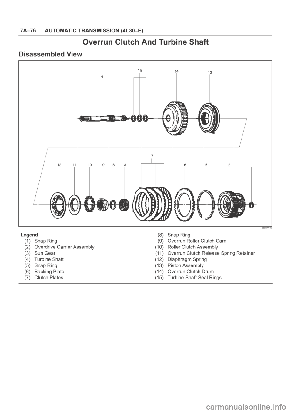
Overrun Clutch And Turbine Shaft
Disassembled View
252RW005
Legend
(1) Snap Ring
(2) Overdrive Carrier Assembly
(3) Sun Gear
(4) Turbine Shaft
(5) Snap Ring
(6) Backing Plate
(7) Clutch Plates(8) Snap Ring
(9) Overrun Roller Clutch Cam
(10) Roller Clutch Assembly
(11) Overrun Clutch Release Spring Retainer
(12) Diaphragm Spring
(13) Piston Assembly
(14) Overrun Clutch Drum
(15) Turbine Shaft Seal Rings
Page 5766 of 6000

7A–77 AUTOMATIC TRANSMISSION (4L30–E)
Disassembly
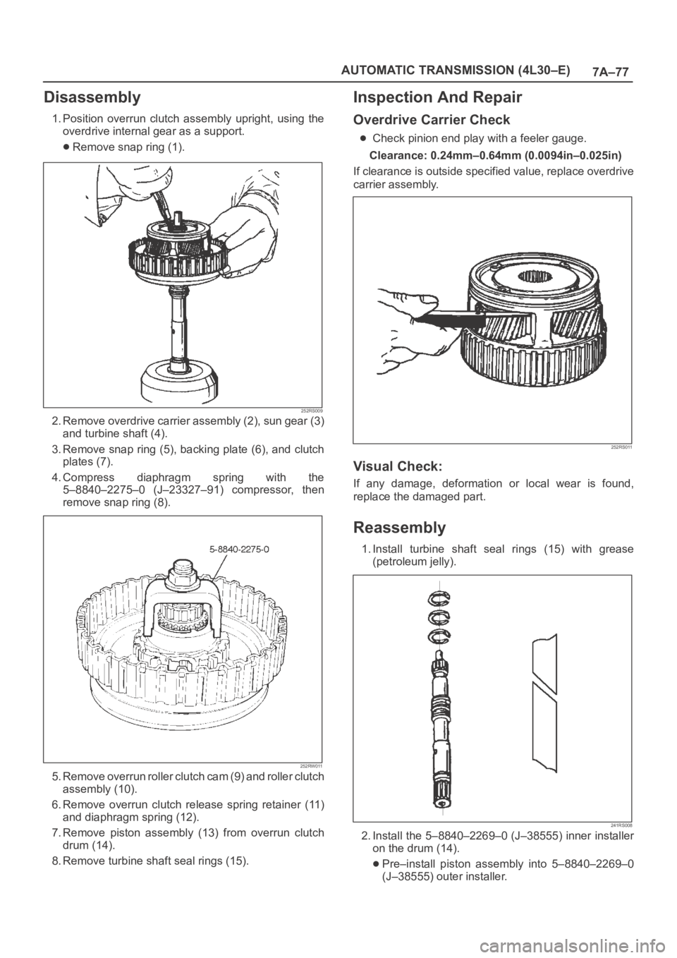
1. Position overrun clutch assembly upright, using the
overdrive internal gear as a support.
Remove snap ring (1).
252RS009
2. Remove overdrive carrier assembly (2), sun gear (3)
and turbine shaft (4).
3. Remove snap ring (5), backing plate (6), and clutch
plates (7).
4. Compress diaphragm spring with the
5–8840–2275–0 (J–23327–91) compressor, then
remove snap ring (8).
252RW011
5 . R e m o v e o v e r r u n r o l l e r c l u t c h c a m ( 9 ) a n d r o l l e r c l u t c h
assembly (10).
6. Remove overrun clutch release spring retainer (11)
and diaphragm spring (12).
7. Remove piston assembly (13) from overrun clutch
drum (14).
8. Remove turbine shaft seal rings (15).
Inspection And Repair
Overdrive Carrier Check
Check pinion end play with a feeler gauge.
Clearance: 0.24mm–0.64mm (0.0094in–0.025in)
If clearance is outside specified value, replace overdrive
carrier assembly.
252RS011
Visual Check:
If any damage, deformation or local wear is found,
replace the damaged part.
Reassembly
1. Install turbine shaft seal rings (15) with grease
(petroleum jelly).
241RS008
2. Install the 5–8840–2269–0 (J–38555) inner installer
on the drum (14).
Pre–install piston assembly into 5–8840–2269–0
(J–38555) outer installer.
Page 5767 of 6000

7A–78
AUTOMATIC TRANSMISSION (4L30–E)
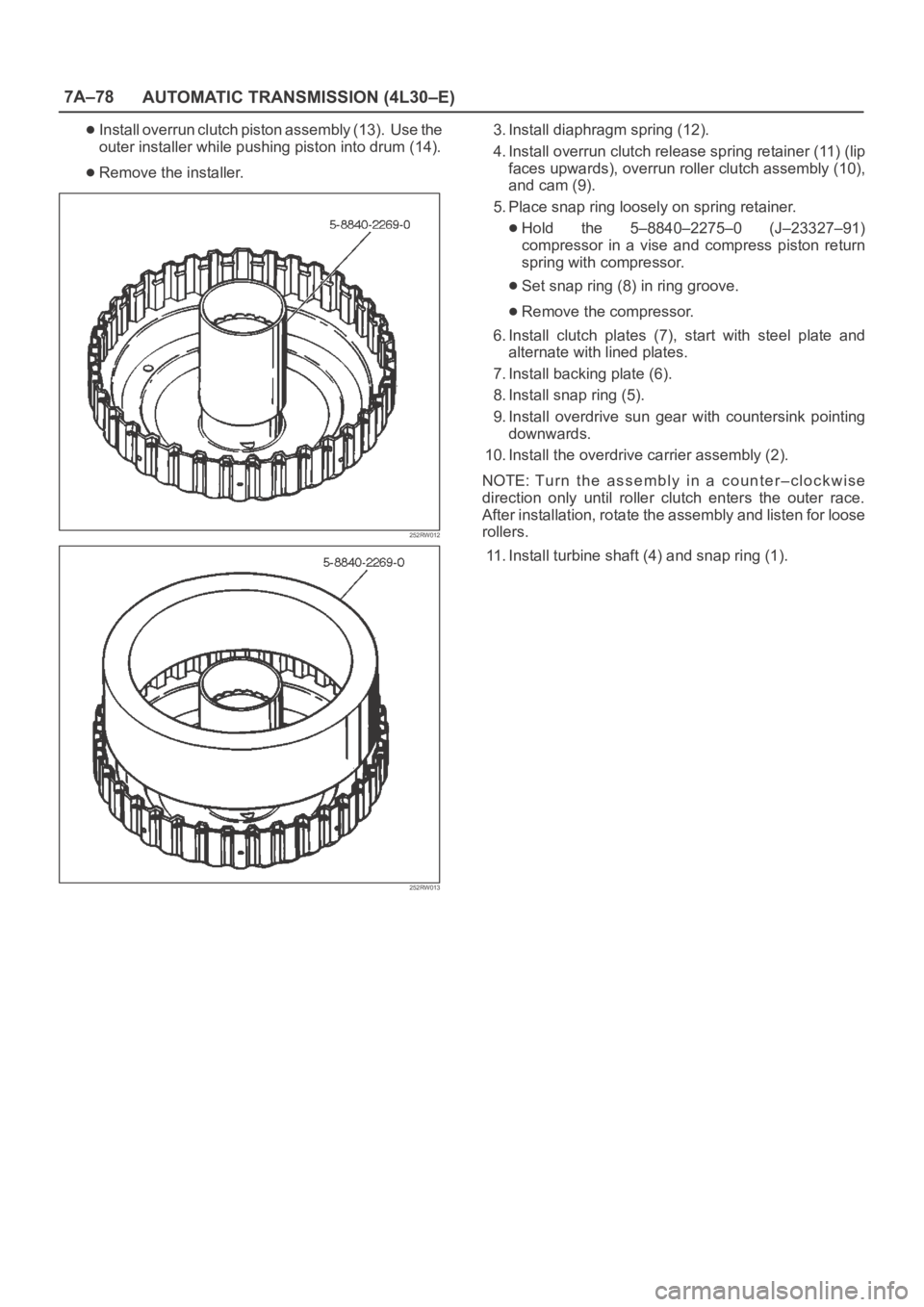
Install overrun clutch piston assembly (13). Use the
outer installer while pushing piston into drum (14).
Remove the installer.
252RW012
252RW013
3. Install diaphragm spring (12).
4. Install overrun clutch release spring retainer (11) (lip
faces upwards), overrun roller clutch assembly (10),
and cam (9).
5. Place snap ring loosely on spring retainer.
Hold the 5–8840–2275–0 (J–23327–91)
compressor in a vise and compress piston return
spring with compressor.
Set snap ring (8) in ring groove.
Remove the compressor.
6. Install clutch plates (7), start with steel plate and
alternate with lined plates.
7. Install backing plate (6).
8. Install snap ring (5).
9. Install overdrive sun gear with countersink pointing
downwards.
10. Install the overdrive carrier assembly (2).
NOTE: Tu r n t h e a s s e m b l y i n a c o u n t e r – c l o c k w i s e
direction only until roller clutch enters the outer race.
After installation, rotate the assembly and listen for loose
rollers.
11. Install turbine shaft (4) and snap ring (1).
Page 5768 of 6000

7A–79 AUTOMATIC TRANSMISSION (4L30–E)
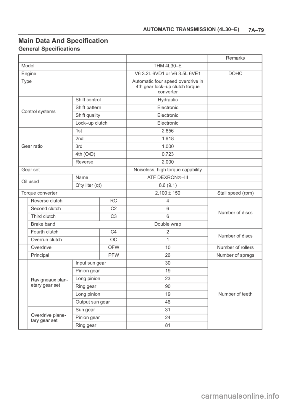
Main Data And Specification
General Specifications
Remarks
ModelTHM 4L30–E
EngineV6 3.2L 6VD1 or V6 3.5L 6VE1DOHC
Ty p eAutomatic four speed overdrive in
4th gear lock–up clutch torque
converter
Shift controlHydraulic
Control systemsShift patternElectronicControl systemsShift qualityElectronic
Lock–up clutchElectronic
1st2.856
2nd1.618
Gear ratio3rd1.000
4th (O/D)0.723
Reverse2.000
Gear setNoiseless, high torque capability
Oil usedNameAT F D E X R O N–IIIOil usedQ’ty liter (qt)8.6 (9.1)
Torque converter2,100 150Stall speed (rpm)
Reverse clutchRC4
Second clutchC26Number of discsThird clutchC36Number of discs
Brake bandDouble wrap
Fourth clutchC42Number of discsOverrun clutchOC1Number of discs
OverdriveOFW10Number of rollers
PrincipalPFW26Number of sprags
Input sun gear30
Pinion gear19
Ravigneaux plan-Long pinion23g
etary gear setRing gear90
Long pinion19Number of teeth
Output sun gear46
Odi l
Sun gear31
Overdrive plane-
tary gear setPinion gear24tary gear set
Ring gear81
Page 5769 of 6000
7A–80
AUTOMATIC TRANSMISSION (4L30–E)
Torque Specifications
E07RY00011
Page 5770 of 6000
7A–81 AUTOMATIC TRANSMISSION (4L30–E)
E07RW079
Trending: interior light, maintenance schedule, tire size, horn, service interval, oil dipstick, fuel pump


