lock OPEL GT-R 1973 Service Manual
[x] Cancel search | Manufacturer: OPEL, Model Year: 1973, Model line: GT-R, Model: OPEL GT-R 1973Pages: 625, PDF Size: 17.22 MB
Page 453 of 625

7C- 92
1973 OPEL SERVICE MANUAL
Figure 7C-84Figure
7C-855. Unhook detent cable from detent valve. See Figure7c-87.
6. Pry detent cable pipe out of retainers.
7. Unscrew upper and lower adjuster nuts and
remove detent cable (on Manta models, loosen lock
nut and screw adjuster out of bulkhead).
Installation
1. Route cable and place in retainers,
2. Place cable in upper bracket and install upper and
lower adjuster nuts and retainer (on Manta models,
screw adjuster into bulkhead).
3. Hook detent cable to valve and install retainer.Figure
7C-86Figure
7C.87
AdjustmentBefore carrying out any adjustment to the detent
cable, it is essential that the throttle control linkage
is correctly adjusted so that full throttle opening is
obtained at the carburetor.
After the throttle control linkage has been set, the
adjustment for the detent cable may be checked as
FOllOWS:1. Position accelerator to full throttle (pedal is nol
fully depressed at full throttle) and loosen and
tighten upper and lower adjuster nuts of detent cable
Page 455 of 625

7C. 941973 OPEL SERVICE MANUAL
7. Drive out retaining pin and shaft and remove se-
lector detent. See Figure 7C-93.Figure
7C-93Figure
7C-94 - Exploded View of Selector Lever
8. To replace bowden cable in selector lever, knock
off selector handle, remove screws from clamping
piece and pull knob.
9. Remove pull knob and bowden cable, taking care
not to lose lock bolt bushing, thrust springs, ‘and
washer.
10. Place thrust spring, bushing, washer, and thrust
spring onto new bowden cable, in that order, and
insert cable into selector lever.
1 I. Slide pull onto selector lever and clamping piece
onto cable.
12. Heat up new selector lever handle in water to 176
degrees F. and push onto selector lever.
13. Set dimension between pull knob and selector
lever handle at
.4 inch and tighten set screws.
14. Lubricate selector lever detent and shaft. Install
detent, align selector lever with support, install shaft,
and drive in new retaining pin.
15. Install assembly to support housing and install
intermediate selector lever.
16. Install assembly to vehicle and install neutral
start switch.
17. Install console lights and cigar lighter connec-
tions to console and install console to vehicle.
18. Lubricate and connect selector rod to intermedi-
ate selector lever and adjust according to Figure 7C-
198.
MAJOR REPAIRREMOVAL AND INSTALLATION OF AUTOMATIC
TRANSMISSION
Removal
- Opel 1900 and Manta
I. Disconnect battery.
2. Remove dipstick.
3. Remove screws from fan shroud.
4. Remove 2 upper starter bolts.
5. Raise car and provide support for front and rear
and drain oil.
6. Remove bolts from engine support brackets, both
sides. Let brackets hang by front bolts. See Figure7c-105.
7. Remove flywheel cover pan.
8. Remove exhaust pipe from manifold and unhook
rubber tailpipe suspension.
9. Remove drive shaft. Do not misplace thrust spring
in spline.
10. Disconnect cooler lines at flexible hoses.
II. Detach both stabilizer supports from
crossmem-ber to body supports and loosen stabilizer bolts in
lower control arms. See Figure X-84, Callout “B”,
Page 456 of 625

AUTOMATIC TRANSMISSION 7C- 95
12. Place suitable jack under transmission and
remove transmission support bolts.
13. Lower transmission enough to remove detent
cable and modulator vacuum line.
14. Remove speedometer cable.
15. Remove selector lever.
16. Mark flywheel and converter for reassembly in
same position, and remove converter to flywheel
bolts. See Figure 7C-106.17. Remove converter housing to engine bolts and
tiller tube.
18. Pry transmission loose from engine.
19. Keep rear of transmission lower than front to
prevent converter from falling and install converter
holding fixture J-21366. Lower transmission and
move to bench.
Installation. Opel 1900 and Manta1. Assemble transmission to suitable jack and raise
transmission into position. Rotate converter to per-
mit coupling of fly wheel and converter with original
relationship. Remove J-21366.
2. Install tiller tube and converter housing to engine
block bolts. Torque to 35 lb. ft. DO NOT over
torque.
3. Install flywheel to converter bolts. Torque to 30 lb.
ft.4. Install detent cable to transmission.
5. Connect oil cooler lines.
6. Install lower bolt on starter. Torque to 40 lb. ft.
7. Connect shift linkage to transmission.
8. Connect modulator line.
9. Connect speedometer cable.
10. Install transmission support.
11. Install drive shaft. Torque U-Bolts to 18 lb. ft.
12. Install flywheel cover pan. Torque to 15 lb. ft.
13. Install engine support brackets.
14. Reconnect exhaust system.15. Attach stabilizer supports and tighten stabilizer
bolts in lower control arms.
16. Lower car.
17. Install starter bolts. Torque to 40 lb. ft.
18. Reconnect battery.
19. Fill transmission with fluid as described in
Specifications. Check selector lever and detent cable
adjustment.
Removal GT1. Disconnect battery.
2. Remove dipstick.
3. Pull throttle control rod off ball pin.
4. Remove screws from fan shroud.
5. Raise car and provide support for front and rear.
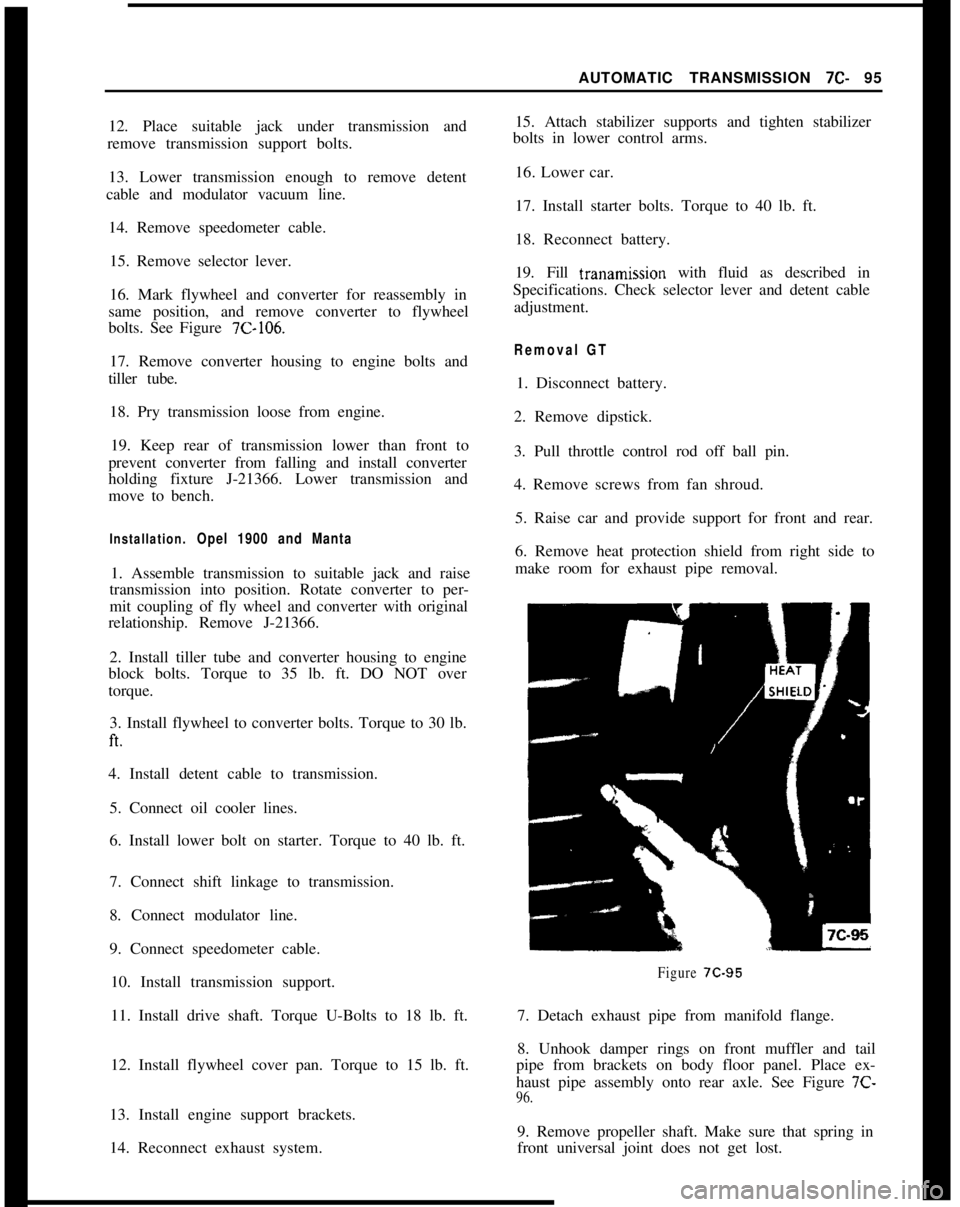
6. Remove heat protection shield from right side to
make room for exhaust pipe removal.
Figure 7C-957. Detach exhaust pipe from manifold flange.
8. Unhook damper rings on front muffler and tail
pipe from brackets on body floor panel. Place ex-
haust pipe assembly onto rear axle. See Figure 7C-
96.9. Remove propeller shaft. Make sure that spring in
front universal joint does not get lost.
Page 462 of 625

AUTOMATIC TRANSMISSION 7C-101
Figure 7C-1 16
-117Figure
7C-118 GT Models
Figure 7C-1 17 GT Modelsthat one case services both models and is machined
to accept selector lever on either side with the unused
hole being plugged.
1. Remove retaining ring From parking actuator rod
to selector inner lever. See Figure 7C-119.
2. Remove selector inner lever locking nut from se-
lector lever shaft.
3. Remove selector inner lever from selector lever
shaft.4. Remove selector lever shaft spring pin by pulling
upwards with small pliers.Figure
7C-1195. Remove selector lever shaft. See Figure 7C-120.
6. Remove selector lever shaft oil seal and discard.
Removal of Modulator Assembly
This operation can be performed with transmission
in vehicle using tool J-23
100.1. Remove vacuum modulator From transmission
case. See Figure
7C-94. Care should be taken not to
lose the modulator plunger.
Page 478 of 625

AUTOMATIC TRANSMISSION 7C-117WIRE CRIMPED
INTO COPPERTUBING
Figure 7C-178
19. Inspect condition of the third clutch composition
and steel plates. Do not diagnose a composition
drive plate by color,A. Dry composition plates with compressed air and
inspect the composition surface for:
1. Pitting and flaking
2. Wear
3. Glazing
4. Cracking
5. Charring
6. Chips or metal particles imbedded in lining
If a composition drive plate exhibits any of the above
conditions, replacement is required.
B. Wipe steel plates dry and check for heat discolora-
tion. If the surface is smooth and an even color smear
is indicated, the plates should be reused. If severe
heat spot discoloration or surface
scutXng is in-
dicated, the plates must be replaced.
20. Install third clutch plates into third clutch drum
beginning with a steel plate, composition plate, steel
plate, composition plate, etc. Use a liberal amount of
transmission fluid.
21. Inspect thrust washer and needle thrust bearing
for damage. Replace if necessary.
22. Install thrust washer and bearing onto input
shaft. Secure with petroleum jelly (unmedicated).23. Inspect sprag assembly for wear, damage orsprags that freely fall out of cage. Inspect input sun
gear for chipped or nicked teeth or abnormal wear.
Replace part if necessary.
24. Install sprag onto third clutch hub with groove
on sprag cage outer diameter toward input sun gear.
See Figure
7C-179.Figure 7C-179
25. Install sprag race and retainer assembly over
sprag assembly. Holding input sun gear with left
hand, sprag race and retainer assembly should “lock
up” when turned with right hand in a clockwise
direction and should rotate freely when turned coun-
terclockwise. See Figure
7C-180.Figure 7C-180
Page 479 of 625

712.1191973 OPEL SERVICE MANUAL
26. Align third clutch composition plates and install
third clutch hub to index with the third clutch platesplines. Input sprag, race, and retainer assembly
must also spline into third clutch drum. See Figure7c-181...-I-AND INPUT SPRAG
Disaseembly, Inspection and Reassembly of
Palentary Carrier1. Inspect the planetary carrier and output shaft for
distortion or damage.
2. Inspect the planetary pinions for excessive wear or
damage, such as chipped teeth.
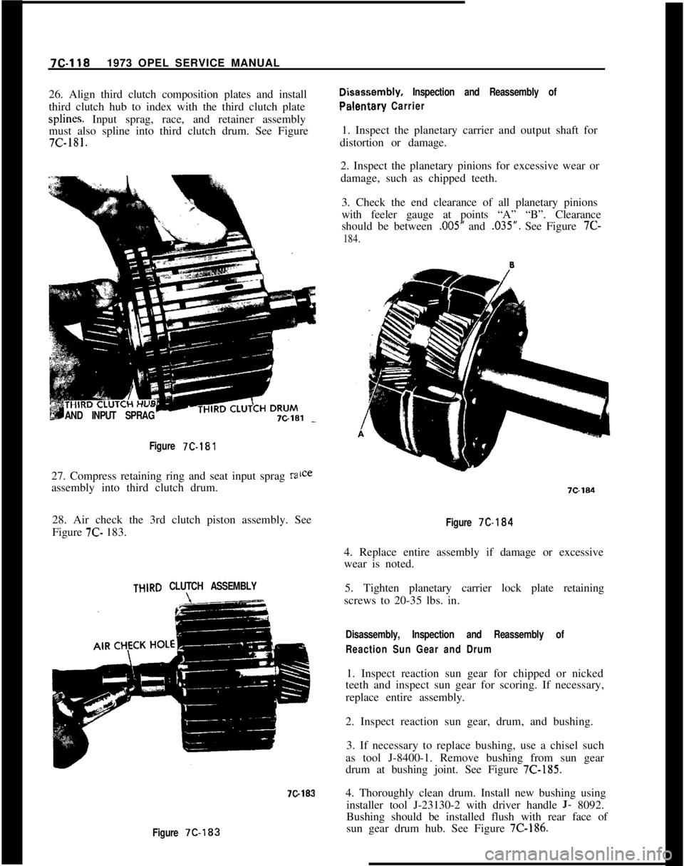
3. Check the end clearance of all planetary pinions
with feeler gauge at points “A” “B”. Clearance
should be between
,005” and .035”. See Figure 7C-
184.
Figure
7C-18127. Compress retaining ring and seat input sprag
raassembly into third clutch drum.
28. Air check the 3rd clutch piston assembly. See
Figure 7C- 183.
THlRD CLUTCH ASSEMBLY
7C183
Figure 7C-183
Figure 7C-184
4. Replace entire assembly if damage or excessive
wear is noted.
5. Tighten planetary carrier lock plate retaining
screws to 20-35 lbs. in.
Disassembly, Inspection and Reassembly of
Reaction Sun Gear and Drum1. Inspect reaction sun gear for chipped or nicked
teeth and inspect sun gear for scoring. If necessary,
replace entire assembly.
2. Inspect reaction sun gear, drum, and bushing.
3. If necessary to replace bushing, use a chisel such
as tool J-8400-1. Remove bushing from sun gear
drum at bushing joint. See Figure
7C-185.4. Thoroughly clean drum. Install new bushing using
installer tool J-23130-2 with driver handle
J- 8092.
Bushing should be installed flush with rear face of
sun gear drum hub. See Figure
7C-186.
Page 481 of 625

7C-1201973 OPEL SERVICE MANUAL
4. Inspect the secondary valve spring for distortion
or breakage.
5. Clean in solvent, air clean, and blow out all oil
passages. Inspect all oil passages, valve bores for
nicks, burrs or varnish in governor body. Replace if
necessary.6. Install roll pin flush to
,010” below the front face.
7. Install primary valve in governor placing the small
portion of the valve in
first. Use liberal amount of
transmission fluid. There is no spring for the primary
valve.
8. Install secondary valve with small spool portion of
valve in
first.9. Install secondary valve spring.
10. Depress secondary valve spring with small screw
driver and install retainer.
Disassembly, Inspection and Reassembly of
Governor Hub1. Inspect the three oil seal rings. See Figure
7C-189.Figure 7C.189
2. Remove governor hub oil screen. Inspect screen
and clean with solvent and air dry. Replace if neces-
sary. See Figure 7C-191.
3. Install oil screen flush to governor hub.
4. Inspect governor hub splines for cracks or chipped
teeth in splines. Replace governor hub if required.Figure 7C-191
Disassembly, Inspection end Reassembly of
Extension Housing1. Inspect extension housing for damage. Replace
housing if necessary.
2. Inspect parking
paw1 and spring for damage. Re-
place if necessary.
3. If lubricant leakage was noted prior to removal ofU-Joint from extension housing, extension housing
rear seal should be replaced.
4. Use screw driver to pry out extension housing seal.
5. Inspect extension housing bushing. If worn, scored
or damaged, bushing can be removed with remover
and installer tool J-21424-9 used with driver handle
J- 8092. See Figure
7C-192.6. Clean extension housing of dirt and foreign mat-
ter. Install new extension housing bushing using
remover/installer tool J-21424-9 with driver handle
J- 8092. Bushing must be installed flush to shoulder
of exi:ension housing. See Figure 7C-192.
7. Install new extension housing seal using installer
tool
Jo-21426. See Figure 7C-193.
Disassembly, Inspection and Reassembly of Servo
Piston1. Remove servo piston apply rod
2. Holding servo piston sleeve at flat portion of sleeve
with wrench, loosen the adjusting bolt lock nut and
remove. See Figure
7C-194.
Page 486 of 625

AUTOMATIC TRANSMISSION 7C-1251. CASE VENT4.3RD CLUTCH7.SUCTION
2. CONVERTER OUT5MODULATOR8.LINE/3.2ND CLUTCH
6. BOOST9.REVERSEFigure 7C-202 Case Front View Oil Passage
Identification
7.
!nspect reaction sun gear drum bushing sleeve
inside case at rear for scoring. If necessary, replace
sleeve before installing rear case bushing.
8. Remove sleeve by grinding. Care must be used in
order that aluminum case is not damaged when
grinding sleeve.
9. Install new sleeve using installer tool J-23130-7
and driver handle J-8092.
10. Install new case bushing using remover and in-
staller tool J-23130-3 and driver handle J-8092.
Bushing should be installed flush with case at rear.
See Figure
7C-203.Figure 7C-2031. Drain Converter. If clutch disc material or
foreign matter has been found while draining con-
verter,
replace entire converter assembly as it can not be
cleaned properly.
2. Air check converter for leaks using converter
checking tool J-21369. Install tool and tighten. Ap-
ply 80 psi air pressure to tool. See Figure
7C-204.Figure 7C-204
3. Submerge in water and check for leaks.
4. Check converter hub surfaces for scoring or wear.
Installation of Selector Lever and Shaft1. Install new selector lever shaft oil seal in case.
Insert selector lever shaft through case from outside.
Care should be exercised so that oil seal is not da-
maged. See Figure
7C-206.2. Insert spring pin in case to secure selector lever
shaft.3. Guide selector lever over shaft and secure with
lock nut.
4. Insert parking
paw1 actuator rod from front of the
case and through hole in case at rear. See Figure 7C-
207.5. Install parking
paw1 actuator rod retaining ring.
Installation of Low Band1. Turn transmission case so that front of case is
upward.
Page 493 of 625

7C-1321973 OPEL SERVICE MANUAL
Figure 7C-226
Figure 7C.224
Figure 7C-225
4. Using 3/16” hex head wrench on servo adjusting
bolt, adjust servo apply rod by tightening adjusting
bolt to 40 lbs. in. Back off bolt five (5) turns. exact/u.See Figure
7C-226.5. Tighten lock nut holding adjusting bolt and sleeve
firm with hex head wrench. See Figure
7C-227.
installation of Valve Body
1. I&all steel balls in oil passages in case. See Figure
7C-228.Figure 7C-227
2. Install new case to transfer plate gasket.
3. Locate guide pins in transmission case for correct
alignment of valve body and transfer plate. See Fig-
ure
7C-229.4. Install manual valve into valve body bore using
liberal amount of transmission fluid.
5. Install long side of manual valve link pin into
manual valve. See Figure
7C-230.
Page 497 of 625

7C-1361973 OPEL SERVICE MANUALshould be secured to keep the front wheels in a
straight-ahead position.sand,. mud, or snow, move the selector lever from
“D” to “R” in a repeat pattern while simultaneously
applying moderate pressure to the accelerator. DoRocking Carnot race engine. Avoid spinning wheels when trying
If it becomes necessary to rock the car to free it fromto free the car.
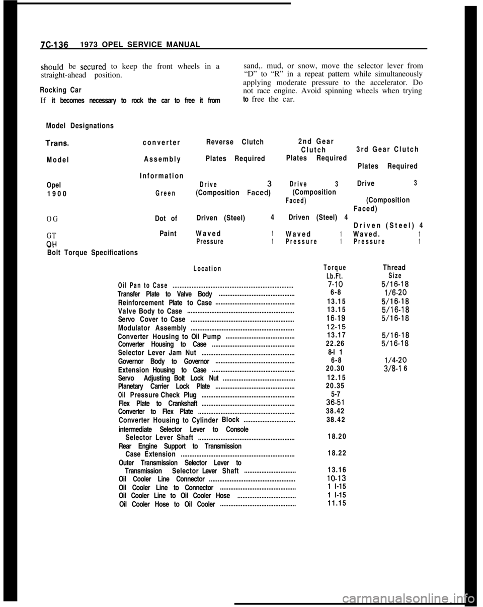
Model DesignationsTrans.
converterReverse Clutch
ModelAssemblyPlates Required2nd Gear
Clutch3rd Gear Clutch
Plates Required
Plates RequiredOpel
1900
OG
GT
CIHInformation
Drive
(Composition Faced:
Drive3Drive3
Green
(Composition
Faced)(CompositionFaced)
Dot ofDriven (Steel)4Driven (Steel) 4
Driven (Steel) 4
PaintWaved1Waved1Waved.1Pressure1Pressure1Pressure1-.
Bolt Torque Specifications
Location
Oil Pan to Case......................................................................Transfer Plate to Valve Body............................................
ReinforcementPlatetoCase..............................................
ValveBodytoCase..............................................................
ServoCovertoCase............................................................
Modulator Assembly............................................................
ConverterHousingtoOilPump........................................
Converter Housing to Case................................................
Selector Lever Jam Nut......................................................
Governor Body to Governor..............................................
ExtensionHousing to Case................................................
Servo AdjustingBolt Lock Nut..........................................
Planetary Carrier Lock Plate..............................................
OilPressureCheckPlug......................................................
Flex Plate to Crankshaft......................................................
Converter to Flex Plate........................................................
ConverterHousingtoCylinderBlock..............................
intermediate Selector Lever to Console
Selector Lever Shaft........................................................
Rear Engine Support to Transmission
CaseExtension..................................................................
Outer Transmission Selector Lever to
TransmissionSelectorLeverShaft..............................
Oil Cooler Line Connector..................................................
Oil Cooler Line to Connector............................................
Oil Cooler Line to Oil Cooler Hose..................................
Oil Cooler Hose to Oil Cooler............................................
Torque
Lb.Ft.7-10
6-8
13.15
13.1516-1812.15
13.17
22.26
8-l 1
6-8
20.30
12.15
20.35
5-736.5
138.42
38.42
Thread
Size
5/16-18
l/6-20
5/16-18
5/16-18
5/16-18
5/16-18
5/16-18
l/4-20
3/8-l 6
18.20
18.22
13.1610-13
1 l-15
1 l-15
11.15