remove seats OPEL GT-R 1973 Service Manual
[x] Cancel search | Manufacturer: OPEL, Model Year: 1973, Model line: GT-R, Model: OPEL GT-R 1973Pages: 625, PDF Size: 17.22 MB
Page 18 of 625
LUBRICATION AND MAINTENANCE OC-9
4. Remove dipstick and wipe clean.
5. Reinsert dipstick untip cap seats.
6. Remove dipstick and note reading.
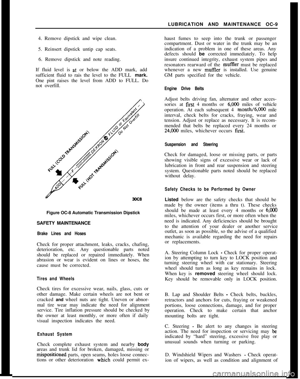
If fluid level is at, or below the ADD mark, add
sufficient fluid to rais the level to the FULL mark.
One pint raises the level from ADD to FULL. Do
not overfill.
3OC8Figure OC-8 Automatic Transmission Dipstick
SAFETY MAINTENANCE
Brake Lines and HosesCheck for proper attachment, leaks, cracks, chafing,
deterioration, etc. Any questionable parts noted
should be replaced or repaired immediately. When
abrasion or wear is evident on lines or hoses, the
cause must be corrected.
Tires and WheelsCheck tires for excessive wear, nails, glass, cuts or
other damage. Make certain wheels are not bent or
cracked and wheel nuts are tight. Uneven or abnor-
mal tire wear may indicate the need for alignment
service. Tire inflation pressure should be checked by
the owner at least monthly, or more often if daily
visual inspection indicates the need.
Exhaust SystemCheck complete exhaust system and nearby body
areas and trunk lid for broken, damaged, missing orm&positioned parts, open seams, holes loose connec-
tions or other deterioration wiuch could permit ex-haust fumes to seep into the trunk or passenger
compartment. Dust or water in the trunk may be an
indication of a problem in one of these areas. Any
defects should be corrected immediately. To help
insure continued integrity, exhaust system pipes and
resonators rearward of the muftler must be replaced
whenever a new mufIler is installed. Use genuine
GM parts specified for the vehicle.
Engine Drive BeltsAdjust belts driving fan, alternator and other acces-
sories at first 4 months or
6,ooO miles of vehicle
operation. At each subsequent 4 month/6,000 mile
interval, check belts for cracks, fraying, wear and
tension. Adjust or replace as necessary. It is recom-
mended that belts be replaced every 24 months or
24,C00 miles, whichever occurs first.
Suspension and SteeringCheck for damaged, loose or missing parts, or parts
showing visible signs of excessive wear or lack of
lubrication in front and rear suspension and steering
system. Questionable parts noted should be replaced
without delay.
Safety Checks to be Performed by OwnerListed below are the safety checks that should be
made by the owner (items a thru t). These checks
should be made at least every 4 months or
6,ooOmiles, whichever occurs first, or more often when the
need is indicated. Any deficiencies should be brought
to the attention of your dealer or another service
outlet, as soon as possible, so the advise of a qualified
mechanic is available regarding the need for repairs
or replacements.
A. Steering Column Lock
_ Check for proper operat-
ion by attempting to turn key to LOCK position and
turning steering wheel with car stationary. Steering
wheel should turn as long as key remains in lock.
When key is removed steering wheel should lock.
Key should be removable only in LOCK position.
B. Lap and Shoulder Belts
- Check belts, buckles,
retractors and anchors for cuts, fraying or weakened
portions, loose connections, damage, and for proper
operation. Check to make certain that anchor
mounting bolts are tight.
C. Steering
- Be alert to any changes in steering
action. The need for inspection or servicing may
beindicated by “hard” steering, excessive free play or
unusual sounds when turning or parking.
D. Windshield Wipers and Washers
- Check operat-
ion of wipers, as well as condition and alignment of
Page 158 of 625

SEATS, INTERIOR TRIM AND HEADLININGZG-35
2. Push off side panel trim pad. Trim pad is held in
position by a retaining button.
REMOVAL AND INSTALLATIONOF HEADLINING
Removal
1. Disconnect battery.
2. Lift out rear seat cushion (sedans only).
3. From trunk area, loosen tabs holding cardboard
against rear seat cross brace and lift out cardboard
(sedans only).
4. Pry up two tabs holding lower portion of rear seat
back in position, swing back of seat forward and lift
out (sedans only).
5. From trunk area pry out parcel shelf plastic retain-
ers and lift out parcel shelf (sedans only).
6. Remove rear-view mirror, sun visors, interior
lamp, assist straps and coat hooks. Remove front and
rear windows on all but Wagon Models. On Wagons,
remove the front window and the quarter windows.
7. Work door opening pinchweld finishing strip
away from pinchweld as far as necessary to expose
edge of headlining.
8. Start at: left or right windshield pillar and pry
headlining loose.
9. Roll back headlining to expose metal tabs securing
headlining listing wire to roof and unhook headhn-
ing front listing wire from metal tabs using a blunt
edge tool.
10. Pull loose the edges of headlining cemented to
door openings, rear quarter window openings, rear
quarter pillar and from under rear window rubber
channel. On rear quarter pillars, slightly bend down
cardboard of rear quarter trim pad to facilitate re-
moval. During removal, special care should be taken
not to tear headlining at seams.
11. After edges of headlining have been pulled loose,
tilt remaining listing wires with headlining forward
or rearward and pull listing wires free from side roof
rails. Lift out headlining and listing wires.
Installation1. Check secureness of noise insulation pad on inside
of roof panel and recement as necessary using asphalt
cement. If headlining is to be replaced, insert listing
wires into headlining according to their markings.
Progressing from the front listing wire to the rear
wire, the left ends of the wires are color coded as
follows:1st listing wire
- No marking, wire is thinner than
other wires
2nd listing wire
- Red
3rd listing wire
- Blue
4th listing wire
_ Green
5th listing wire
- Brown
6th listing wire
- White
2. Install 1st listing wire ends into retainer slots in-
side roof rails and hook listing wire into six metal
tabs above windshield. Lightly bend tabs with a ham-
mer as shown in Figure
2G-8.
HEAOLlN’lNdA-----
26-8Figure
2G-8 Headlining With 1st Listing Wire Hooked
Onto Metal Tabs
LISTINGWIRE
SECTIOND-D
4 26-9Figure 2G-9 2nd and 5th Listing Wire Attachment
Page 160 of 625

SEATS, INTERIOR TRIM AND HEADLINING20.378. If wagon, install front window and quarter win-
dows. It other than wagon, install front and rear
windows.9. Install coat hooks, assist straps, interior lamp, sun
visors, and rear view mirror.
10. Install parcel shelf and plastic retainers (sedans
only).
11. Install rear seat back into position and bend over
tabs holding lower portion of seat back (sedans only).
12. In trunk area instail cardboard against rear seat,
cross brace, and bend over tabs (sedans only).
13. Install rear seat cushion (sedans only).
14. Connect battery.REMOVAL AND INSTALLATION OF REAR SIDE
PANEL TRIM PAD
1, Unscrew shield on lock pillar. See Figure 2G- 11.
2. Pull off sealing strip on lock pillar and rear quarter
window. See Figure 2G- 12.
3. Remove ash tray.
4. Remove rear seat and push retaining button out of
trim pad. See Figure
2G-13.5. Pull out trim pad towards the front.
6. Prior to installation, press together sealing strip
ends to obtain a tight seat.
Page 218 of 625

REAR SUSPENSION3F- 51
REAR SUSPENSION
CONTENTS
Subject
DESCRIPTION AND OPERATION:
Description and Operation of Rear Suspension. . . . . .DIAGNOSIS: (Not Applicable)
MAINTENANCE AND ADJUSTMENTS: (Not
Applicable)
MAJOR REPAIR:
Rear Shock Absorber Removal and Replacement . .
Rear
SpringRemovalandInstallation. . . . . . . . . . . . . . . . . . . . . . . .LowerControlArmReplacement
. . . . . . . . . . . . . . . . . . . . . . . . . . . . . . . .Stabilizer
RodReplacement. . . . . . . . . . . ~ . . . . . . . . . . . . . . . . . . . . . ..-....Track Rod Replacement
. . . . . . . . . . . . . . . . . . . . . . . . . . . . . . . . . . . . . . . . . . . . . . . .SPECIFICATIONS:
Rear
SuspensionSpecifications. . . . . . . . . . . . . . . . . . . . . . . . . . . . . . . . . . . .Page No.3F-5
13F-513F-523F-533F-533F-533F-53
DESCRIPTION AND OPERATIONDESCRIPTION AND OPERATION OF REAR
SUSPENSIONAll Opels utilize the three link rear suspension ar-
rangement. This rear suspension consists of coil
springs, track rod, shock absorbers and lower control
arms.The coil springs set between two seats which arc
situated ahead of the rear axle housing.
The track rod is utilized on all models to control the
lateral stability of the rear axle assembly. It is of
tubular design. A stabilizer rod is used on all Wagons
as well as Fast Backs and Sedans. The GT is not
equipped with a stabilizer rod.
The lower control arms are of tubular design and
function as two links of the three link suspension
system. They are attached to the underbody through
brackets welded to the side rails and to the rear axle
assembly through the front portion of the spring seat
bracket. The lower control arms control the fore and
aft movement of the rear axle assembly.
The third link in this suspension system is the torque
tube which is connected to the differential carrier
and also to the underbody through rubber bushings
in the central joint support bracket.The torque tube in conjunction with the lower con-
trol arms absorb all acceleration and braking torque.
MAJOR REPAIR
REAR SHOCK ABSORBER REMOVALAND INSTALLATION
RemovalNOTE: The trim panel under the spare tire must be
removed on the GT to gain access to attaching nuts.
1. Remove upper attaching nut, retainer and rubber
grommet.
2. Remove lower attaching nut and rubber grommet
retainer, compress shock absorber and remove from
lower mounting pin.
Installation1. Replace upper and lower rubber grommets, if
necessary, before installing shock absorber.
2. Extend shock absorber and position in car. Attach
at lower end first, torque nut to 15 lb.ft. on the GT,
and torque to 47 lb.ft. on the Opel 1900
- Manta.
Page 219 of 625
3F. 521973 OPEL SERVICE MANUAL
3. Install rubber grommet, retainer and self-locking
nut at top of shock absorber. Torque to 10 lb. ft.
Always use new self-locking nuts.
REAR SPRING REMOVAL AND INSTALLATION
Rear Spring Removal1. Raise rear of car with floor jack under differential
carrier and support with jack stands positioned un-
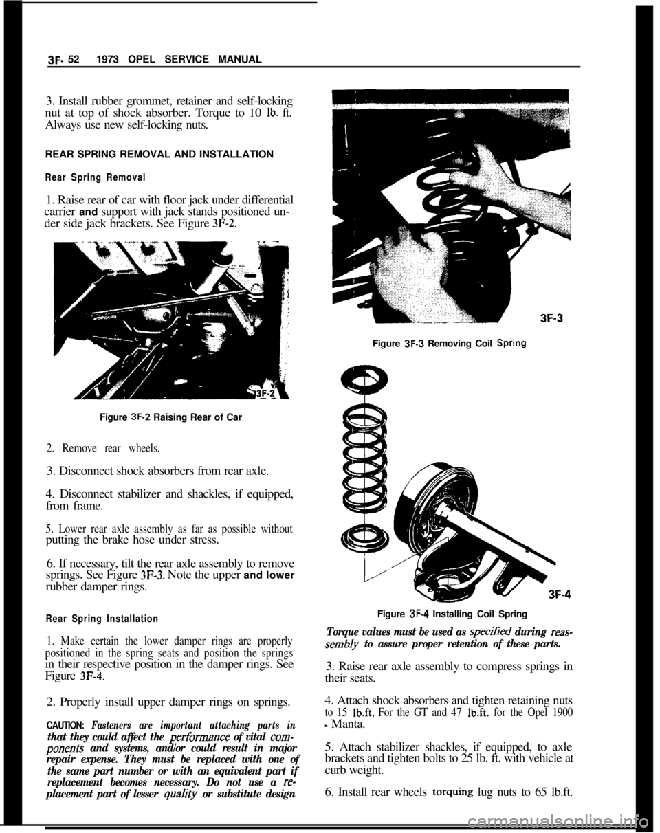
der side jack brackets. See Figure
3F-2.Figure 3F-3 Removing Coil
SpringFigure 3F-2 Raising Rear of Car
2. Remove rear wheels.3. Disconnect shock absorbers from rear axle.
4. Disconnect stabilizer and shackles, if equipped,
from frame.
5. Lower rear axle assembly as far as possible withoutputting the brake hose under stress.
6. If necessary, tilt the rear axle assembly to remove
springs. See Figure
3F-3. Note the upper and lower
rubber damper rings.
Rear Spring Installation
1. Make certain the lower damper rings are properly
positioned in the spring seats and position the springsin their respective position in the damper rings. See
Figure
3F-4.2. Properly install upper damper rings on springs.
CAUTION: Fasteners are important attaching parts in
that they could affect the performance of vital corn-
ponents and systems, and/or could result in major
repair expense. They must be replaced with one of
the same part number or with an equivalent part if
replacement becomes necessary. Do not use a
re-
placement part of lesser
qua/ity or substitute designFigure 3F-4 Installing Coil Spring
Torque values must be used as specitied during reas-
sembly to assure proper retention of these parts.3. Raise rear axle assembly to compress springs in
their seats.
4. Attach shock absorbers and tighten retaining nuts
to 15 Ib.ft. For the GT and 47 lb.ft. for the Opel 1900
- Manta.
5. Attach stabilizer shackles, if equipped, to axle
brackets and tighten bolts to 25 lb. ft. with vehicle at
curb weight.
6. Install rear wheels torquing lug nuts to 65 lb.ft.
Page 241 of 625
4B- 101973 OPEL SERVICE MANUAL
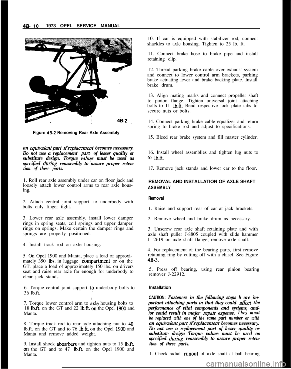
Figure 48-Z Removing Rear Axle Assemblyan equiva/entpart ifreplacement becomes necessary.
Do not use a replacement
part of lesser quality or
substitute design. Torque
values must be used as
specified
during reassembly to assure proper reten-
tion of these parts.1. Roll rear axle assembly under car on floor jack and
loosely attach lower control arms to rear axle hous-
ing.
2. Attach central joint support, to underbody with
bolts only finger tight.
3. Lower rear axle assembly, install lower damper
rings in spring seats, coil springs and upper damper
rings on springs. Make certain the damper rings and
springs are properly positioned.
4. Install track rod on axle housing.
5. On Opel 1900 and Manta, place a load of approxi-
mately 350
Ibs. in luggage conipartment or on the
GT, place a load of approximately 150 lbs. on drivers
seat and raise rear axle far enough for underbody to
clear jack stands.
6. Torque central joint support t$ underbody bolts to
36 lb.ft.
7. Torque lower control arm to
Axle housing bolts to
18
Ib.ft. on the GT and 22 lb.ft. dn the Opel 1900 and
Manta.
8. Torque track rod to rear axle attaching nut to
40lb.ft. on the GT and to 76
lb.ft. on the Opel 1900 and
Manta and remove added weight.
9. Install shock abosrbers and tighten nuts to 15
Ib.ft.on the GT and to 47
Ib.ft. on the Opel 1900 and
Manta.10. If car is equipped with stabilizer rod, connect
shackles to axle housing. Tighten to 25 lb. ft.
11. Connect brake hose to brake pipe and install
retaining clip.
12. Thread parking brake cable over exhaust system
and connect to lower control arm brackets, parking
brake actuating lever and brake backing plate. Install
brake drum.
13. Align mating marks and connect propeller shaft
to pinion flange. Tighten universal joint attaching
bolts to 11
Ib.ft. Bend respective lock plate tabs to
secure nuts or bolts.
14. Connect parking brake cable equalizer and return
spring to brake rod and adjust to specifications.
15. Bleed rear brake system and fill master cylinder.
16. Install wheel assemblies and tighten lug nuts to
65
lb.ft.17. Remove jack stands and lower car to the floor.
REMOVAL AND INSTALLATION OF AXLE SHAFT
ASSEMBLY
Removal1. Raise and support rear of car at jack brackets.
2. Remove wheel and brake drum as necessary.
3. Unscrew rear axle shaft retaining plate and with
axle shaft puller J-8805 coupled with slide hammer
J- 2619 on axle shaft flange, remove axle shaft.
4. For replacement of the bearing parts, first remove
retaining ring by cutting off with a chisel. See Figure4B-3.
5. Press off bearing, using rear pinion bearing
remover J-22912.
Installation
CAUTION: Fasteners in the following steps b are im-
portant attaching parts in that they could at&t
tee
performance of vital components and systems, and-
/or could result in major
repair expense.They must
be replaced with one of the same part number or with
an equivalentpart ifreplacement becomes necessary.
Do not use a replacement part of lesser quality or
substitute design Torque values must be used as
specified
during reassembly to assure proper reten-
tion of these parts.1. Check radial runout of axle shaft at ball bearing
Page 306 of 625
ENGINE MECHANICAL AND MOUNTS6A- 15New inlet valves must not be refaced or lapped with
grinding compound.The correct angle for the intake
and exhaust valve head is 44 degrees.10. Install cylinder head.
11. Adjust valve clearance. See MAINTENANCE
AND ADJUSTMENTS.
7. Inspect valve guides. Worn or pitted guides can be
reamed to accept valves with oversize stems. Over-
size valves are occasionally used in production.
Oversize valves are marked
’ 1 u “2” or “A” and are
stamped into the valve stem end and also stamped
near spark plug hole. See Figure 6A-22.
Replacing Rocker Arm Studs1. When replacing rocker arm studs become
neces-
sary, remove air cleaner, rocker arm cover and
rocker arm.
8. Reseat valve seats in cylinder head in the following
sequence:
Intake
NOTE:The rocker arm studs are screwed into the
cylinder head. A tapered part of the stem serves to
a void stud loosening.With 45 degrees cutter, remove burnt structure until
a metallic bright seat is obtained. Lightly coat valve
head with red lead, insert it into guide and turn it
under light pressure several times back and forth.
Thereby a contact pattern is obtained and the seat
width can be measured. If valve does not seat per-
fectly all around, lightly recut valve seat to the estab-
lished seat width of
,049” - .059” with 30 degrees
correction cutter.
ExhaustThe directions for reconditioning intake valve seats
apply in principle also to exhaust valve seat recondi-
tioning with the exception that the valve seat width
should be
.063-,073 in. and different cutters are em-
ployed.
NOTE:
: OTse new valve seals whenever
valves are reconditioned.9. Lube valves with engine oil and reinstall valves,
valve springs, caps and cap retainers using J-8062.
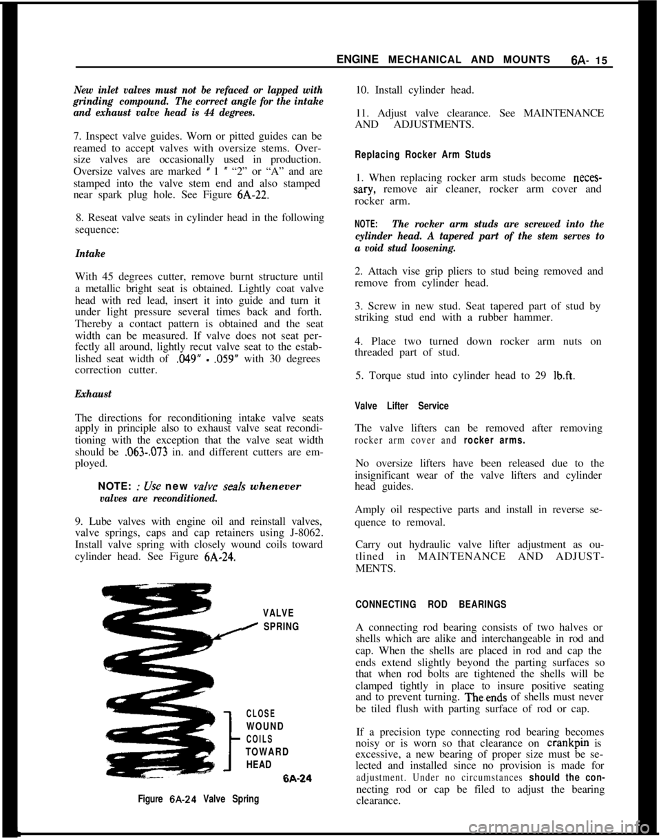
Install valve spring with closely wound coils toward
cylinder head. See Figure
6A-24.2. Attach vise grip pliers to stud being removed and
remove from cylinder head.
3. Screw in new stud. Seat tapered part of stud by
striking stud end with a rubber hammer.
4. Place two turned down rocker arm nuts on
threaded part of stud.
5. Torque stud into cylinder head to 29
lb.ft.
Valve Lifter ServiceThe valve lifters can be removed after removing
rocker arm cover and rocker arms.No oversize lifters have been released due to the
insignificant wear of the valve lifters and cylinder
head guides.
Amply oil respective parts and install in reverse se-
quence to removal.
Carry out hydraulic valve lifter adjustment as ou-
tlined in MAINTENANCE AND ADJUST-
MENTS.
VALVE
I SPRING
CLOSE
WOUND
COILS
TOWARD
HEAD6A-24
Figure 6A-24 Valve SpringCONNECTING ROD BEARINGSA connecting rod bearing consists of two halves or
shells which are alike and interchangeable in rod and
cap. When the shells are placed in rod and cap the
ends extend slightly beyond the parting surfaces so
that when rod bolts are tightened the shells will be
clamped tightly in place to insure positive seating
and to prevent turning. Theends of shells must never
be tiled flush with parting surface of rod or cap.
If a precision type connecting rod bearing becomes
noisy or is worn so that clearance on crankpin is
excessive, a new bearing of proper size must be se-
lected and installed since no provision is made for
adjustment. Under no circumstances should the con-necting rod or cap be filed to adjust the bearing
clearance.
Page 308 of 625
ENGINE MECHANICAL AND MOUNTS6A- 17
seating and to prevent turning.The ends of she//s
must never be tiled flush with parting surface of
crankcase or bearing cap.Crankshaft bearings are the precision type which do
not require reaming to size. Shims are not provided
for adjustment since worn bearings are readily re-
placed with new bearings of proper size. Bearings for
service replacement are furnished in standard size
and undersizes. Under no circumstances should
crankshaft bearing caps be tiIed to adjust for wear in
old bearing.After removal of oil pan, pipe and screen assembly,
perform the following removal, inspection and in-
stallation operations on each crankshaft bearing in
turn so that the crankshaft will be well supported by
the other bearings.
If crankshaft has been removed to check straightness
the following procedure is suggested. Rest crank-
shaft on “V-blocks” at number one and number live
main bearing journals. Check indicator runout at
No. 3 main bearing journal. Total indicator reading
should not exceed
.C012”.1. Since any service condition which affects the
crankshaft bearings may also affect the connecting
rod bearings, it is advisable to inspect connecting rod
bearings
first. If crankpins are worn to the extent
that crankshaft should be replaced or reground, re-
placement of crankshaft bearings only will not be
satisfactory.
If replacement of cylinder block or crankshaft is re-
quired, always check main bearing clearance with
plastic-type gauge to obtain specified limits.
2. Remove one bearing cap, then clean and inspect
lower bearing shell and the crankshaft journal. If
journal surface is scored or ridged, the crankshaft
must be replaced or reground to insure satisfactory
operation with new bearings. Slight roughness may
be polished out with tine grit polishing cloth
thoroughly wetted with engine oil, and burrs may be
honed off with a tine stone.
3. If condition of lower bearing shell and crankshaft
journal is satisfactory, check the bearing clearance
with a plastic-type gauge.
4. When checking a crankshaft bearing with plastic-
type gauging material, turn crankshaft so that oil
hole is up to avoid dripping of oil on the gauge
material. Place paper shims in lower halves of adja-
cent bearings and tighten cap bolts to take the weight
of crankshaft
off the lower shell of beating being
checked.5. If bearing clearance exceeds
.C03”, it is advisable
to install a new bearing; however, if bearing is in
good condition and is not being checked because ofbearing noise, it is not necessary to replace the bear-
ing.6. Loosen all crankshaft bearing cap bolts
l/2 turn,
and remove cap of bearing to be replaced.
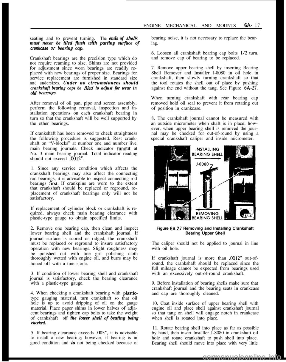
7. Remove upper bearing shell by inserting Bearing
Shell Remover and Installer J-8080 in oil hole in
crankshaft, then slowly turning crankshaft so that
the tool rotates the shell out of place by pushing
against the end without the tang. See Figure
6A-27.When turning crankshaft with rear bearing cap
removed hold oil seal to prevent it from rotating out
of position in crankcase.
8. The crankshaft journal cannot be measured with
an outside micrometer when shaft is in place; how-
ever, when upper bearing shell is removed the jour-
nal may be checked for out-of-round by using a
special crankshaft caliper and inside micrometer.
Figure 6A-27 Removing and Installing Crankshaft
Bearing Upper Shell
The caliper should not be applied to journal in line
with oil hole.
If crankshaft journal is more than
.M)12” out-of-
round, the crankshaft should be replaced since the
full mileage cannot be expected from bearings used
with an excessively out-of-round crankshaft.
9. Before installation of bearing shells make sure that
crankshaft journal and the bearing seats in crankcase
and cap are thoroughly cleaned.
10. Coat inside surface of upper bearing shell with
engine oil and place shell against crankshaft journal
so that tang on shell will engage notch in crankcase
when shell is rotated into place.
11. Rotate bearing shell into place as far as possible
by hand, then insert Installer J-8080 in crankshaft oil
hole and rotate crankshaft to push shell into place.
Bearing shell should move into place with very little
Page 347 of 625

6E- 561973 OPEL SERVICE MANUAL
valve stop screw. Loosen the stop screw until the
valve is completely closed. Turn the screw in l/4turn from closed position, hold, and tighten lock nut.
This is done to insure that the throttle blade will not
stick closed. See Figure
6E-30.PUMPFigure 6E-30 Adjusting Secondary Throttle Valve Gap
24. Install accelerator pump connecting rod in lower
hole of primary throttle shaft lever and cotter pin in
outboard hole at accelerator pump actuating lever
end. Paying attention to proper arrangement of cot-
ter pin and washers. See Figure
6E-2.25. With throttle plate completely closed, there
should be no clearance between the pump levei and
the pump plunger rod.
26. If a clearance is present, loosen 4 accelerator
Figure
6E-31 Accelerator Pump CoverFigure 6C32 Accelerator Pump Cover
pump cover retaining screws and allow the
dia-’phragm spring to push plunger against lever so that
a zero clearance exists. Then retighten the screws.
See Figures
6E-3 1 and 6E-32.27. Insert accelerator pump discharge nozzle so that
the bent tube end points into suction channel of the
primary barrel.
28. Fill the bowl with fuel.
29. With fuel in bowl, slowly open the throttle and
observe the accelerator pump pressure relief valve
exhaust ports and where it seats into the bowl. See
Figure
6E-33. Fuel should not be bleeding back into
the bowl from the exhaust ports or where the relief
valve seats, but a steady stream of fuel should dis-
charge from the discharge nozzle.
30. With fuel in bowl, rapidly open the throttle atid
observe the exhaust ports of the pressure relief valve.
See Figure
6E-33. Fuel should~exhaust’from the ac-
celerator pump pressure relief valve exhaust ports.
3 1. If the pressure relief valve malfunctions, remove
it and replace with a new one.
32. No float adjustment is possible, so check position
of float arm by comparing with a new float of thesame carburetor type. If float arm is bent, replace
float.
Page 474 of 625

AUTOMATIC TRANSMISSION 7C-113
12. Inspect the piston return springs. Evidence of
extreme heat or burning in the area of the clutch may
have caused the springs to take a heat set and would
justify replacement of the springs.
Figure 7C-16313. Inspect second clutch hub bushing for scoring or
wear.14. If necessary, remove second clutch hub bushing
using remover and installer J-23130-6 with driver
handle J-8092. See Figure 7C-164.
P-J-6092
SECOND CLUTCH
DRUM
iJ:23130-6Figure
7C-16415. Clean in solvent to remove any foreign matter.
Install new second clutch hub bushing using tool
J-23 130-6 and driver handle J-8092. Bushing must be
driven in until tool bottoms on bench. See Figure 7C-
164.16. To install second clutch piston into second clutch
drum, use installer tool J-23080 so as not to damage
lip seal. See Figure 7C-165. Use liberal amount of
transmission fluid for ease of installation and to pre-
vent seal damage.
SECOND CLUTCHDRUM
J-23,060Figure
7C-16517. Remove second clutch piston and seal installer
J-23080.18. Install 22 springs and retaining seat on second
clutch piston.
19. Using spring compressor tool J-2590-12 with
adapter J-21420-1 on retaining seat, compress sec-
ond clutch piston return springs. Care should be
taken so that retainer does not catch in snap ring
groove and damage retainer.
20. Install snap ring with snap ring pliers such as
J-
8059.21. Install bronze thrust washer so that the tang seats
in the slot of the second clutch hub. Secure with
petroleum jelly (unmedicated).
22. Inspect condition of composition and steel plates.
Do not diagnose a composition drive plate by co/or.
A. Dry composition plates with compressed air and
inspect the composition surface for:
1. Pitting and flaking
2. Wear
3. Glazing