Peugeot 206 CC 2003 Owner's Manual
Manufacturer: PEUGEOT, Model Year: 2003, Model line: 206 CC, Model: Peugeot 206 CC 2003Pages: 135, PDF Size: 2.11 MB
Page 111 of 135

30-06-2003
PRACTICAL INFORMATION
104
- Pull the tab
Aupwards and remove the protective cover.
- Disconnect the connector.
- Press the end of the securing clip to remove it. Change the faulty bulb.
- On fitting, ensure that the direction notches are in the correct position and that the clip is secured correctly.
- Reconnect the connector.
- Replace the protective cover.
CHANGING A BULB Dipped/main headlamps H7 55W Side lights W5W
Turn the pin connector
Ba quarter turn and remove it.
Change the bulb.
Remarks
- Only touch the bulbs with a dry cloth.
- To replace the bulbs on the right side, remove the wash-wipe reservoir filler pipe first.
- Condensation may form inside the headlamps. It will disappear when the lights are used.
Page 112 of 135
30-06-2003
PRACTICAL INFORMATION105
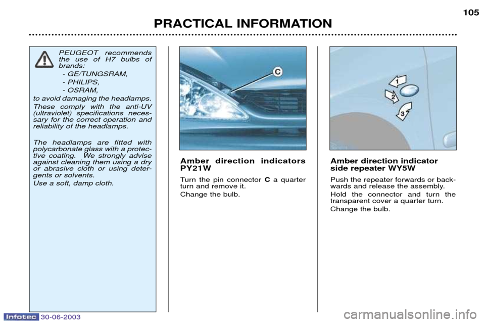
Amber direction indicators PY21W
Turn the pin connector
Ca quarter
turn and remove it. Change the bulb. Amber direction indicator side repeater WY5W Push the repeater forwards or back-
wards and release the assembly. Hold the connector and turn the transparent cover a quarter turn. Change the bulb.
PEUGEOT recommends the use of H7 bulbs ofbrands:
- GE/TUNGSRAM, - PHILIPS,- OSRAM,
to avoid damaging the headlamps.These comply with the anti-UV (ultraviolet) specifications neces-sary for the correct operation andreliability of the headlamps. The headlamps are fitted with polycarbonate glass with a protec-
tive coating. We strongly adviseagainst cleaning them using a dryor abrasive cloth or using deter-gents or solvents. Use a soft, damp cloth.
Page 113 of 135
30-06-2003
PRACTICAL INFORMATION
106
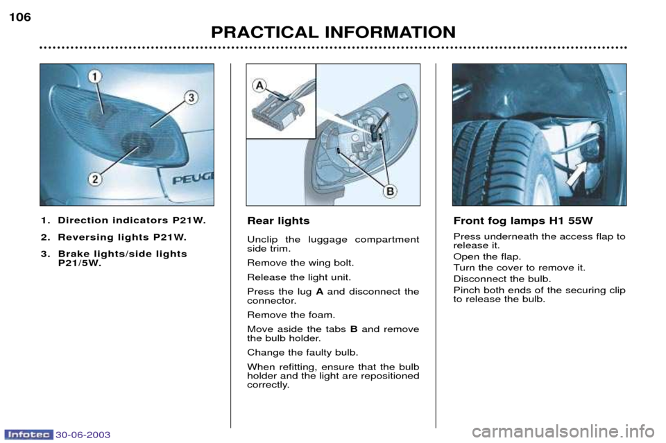
Rear lights Unclip the luggage compartment side trim. Remove the wing bolt.Release the light unit.Press the lug
Aand disconnect the
connector.Remove the foam.Move aside the tabs Band remove
the bulb holder.Change the faulty bulb.When refitting, ensure that the bulb holder and the light are repositioned
correctly.
1. Direction indicators P21W.
2. Reversing lights P21W.
3. Brake lights/side lights
P21/5W.Front fog lamps H1 55W Press underneath the access flap to release it. Open the flap.
Turn the cover to remove it.Disconnect the bulb.Pinch both ends of the securing clip to release the bulb.
Page 114 of 135
30-06-2003
PRACTICAL INFORMATION107
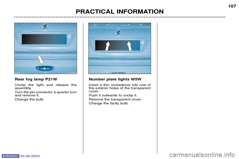
Rear fog lamp P21W Unclip the light and release the
assembly.
Turn the pin connector a quarter turn and remove it. Change the bulb.Number plate lights W5W Insert a thin screwdriver into one of the exterior holes of the transparent
cover. Push it outwards to unclip it.
Remove the transparent cover.Change the faulty bulb.
Page 115 of 135
30-06-2003
PRACTICAL INFORMATION
108
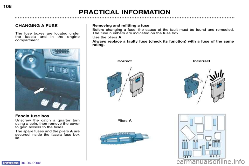
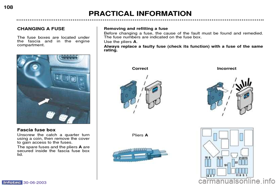
Fascia fuse box Unscrew the catch a quarter turn using a coin, then remove the coverto gain access to the fuses. The spare fuses and the pliers
Aare
secured inside the fascia fuse box lid. Removing and refitting a fuse Before changing a fuse, the cause of the fault must be found and remedied. The fuse numbers are indicated on the fuse box. Use the pliers
A.
Always replace a faulty fuse (check its function) with a fuse of the same rating.
Correct Incorrect
CHANGING A FUSE The fuse boxes are located under the fascia and in the engine compartment.
Pliers A
Page 116 of 135
30-06-2003
PRACTICAL INFORMATION
108
Fascia fuse box Unscrew the catch a quarter turn using a coin, then remove the coverto gain access to the fuses. The spare fuses and the pliers
Aare
secured inside the fascia fuse box lid. Removing and refitting a fuse Before changing a fuse, the cause of the fault must be found and remedied. The fuse numbers are indicated on the fuse box. Use the pliers
A.
Always replace a faulty fuse (check its function) with a fuse of the same rating.
Correct Incorrect
CHANGING A FUSE The fuse boxes are located under the fascia and in the engine compartment.
Pliers A
Page 117 of 135
30-06-2003
PRACTICAL INFORMATION109
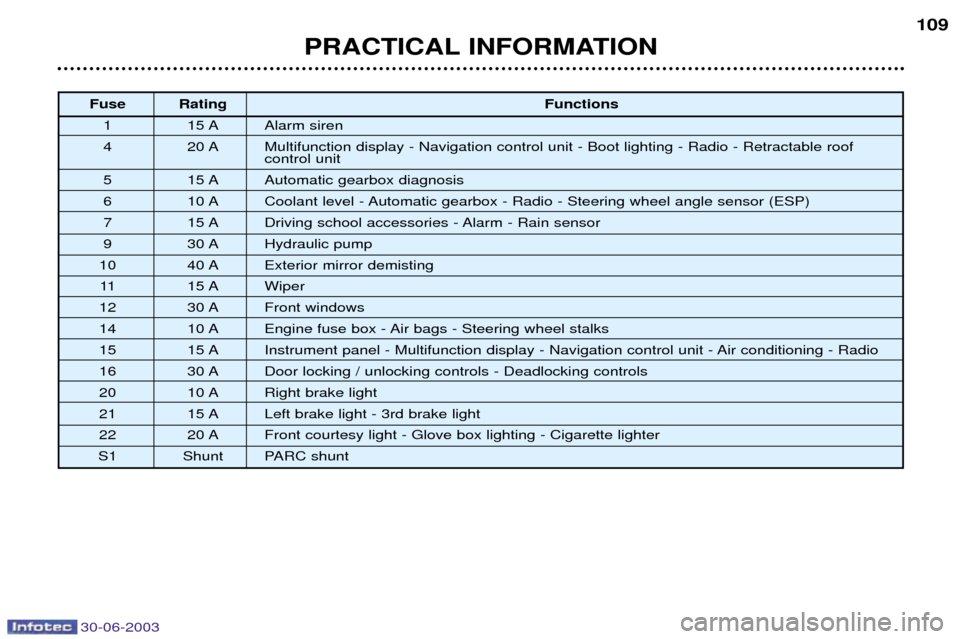
Fuse Rating
Functions
1 15 A Alarm siren
4 20 A Multifunction display - Navigation control unit - Boot lighting - Radio - Retractable roof control unit
5 15 A Automatic gearbox diagnosis
6 10 A Coolant level - Automatic gearbox - Radio - Steering wheel angle sensor (ESP)
7 15 A Driving school accessories - Alarm - Rain sensor
9 30 A Hydraulic pump
10 40 A Exterior mirror demisting 11 15 A Wiper
12 30 A Front windows
14 10 A Engine fuse box - Air bags - Steering wheel stalks
15 15 A Instrument panel - Multifunction display - Navigation control unit - Air conditioning - Radio
16 30 A Door locking / unlocking controls - Deadlocking controls
20 10 A Right brake light
21 15 A Left brake light - 3rd brake light
22 20 A Front courtesy light - Glove box lighting - Cigarette lighter
S1 Shunt PARC shunt
Page 118 of 135
PRACTICAL INFORMATION
110
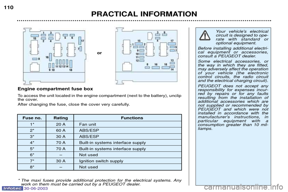
Fuse no. Rating Functions
1* 20 A Fan unit
2* 60 A ABS/ESP
3* 30 A ABS/ESP
4* 70 A Built-in systems interface supply
5* 70 A Built-in systems interface supply
6* Ð Not used
7* 30 A Ignition switch supply
8* Ð Not used
Engine compartment fuse box
To access the unit located in the engine compartment (next to the battery), unclip
the cover.
After changing the fuse, close the cover very carefully.
Your vehicle's electrical circuit is designed to ope-rate with standard oroptional equipment.
Before installing additional electri-cal equipment or accessories,
consult a PEUGEOT dealer. Some electrical accessories, or the way in which they are fitted,may adversely affect the operationof your vehicle (the electroniccontrol circuits, the radio circuitand the electrical charging circuit). PEUGEOT does not accept any responsibility for expenses incur-red by repairs or for any faultsresulting from the installation ofadditional accessories which arenot supplied or recommended byPEUGEOT and which were notinstalled in accordance with themanufacturer's instructions, inparticular equipment with aconsumption greater than 10 mil-liamps.
* The maxi fuses provide additional protection for the electrical systems. Any work on them must be carried out by a PEUGEOT dealer.
or
30-06-2003
Page 119 of 135
30-06-2003
PRACTICAL INFORMATION111
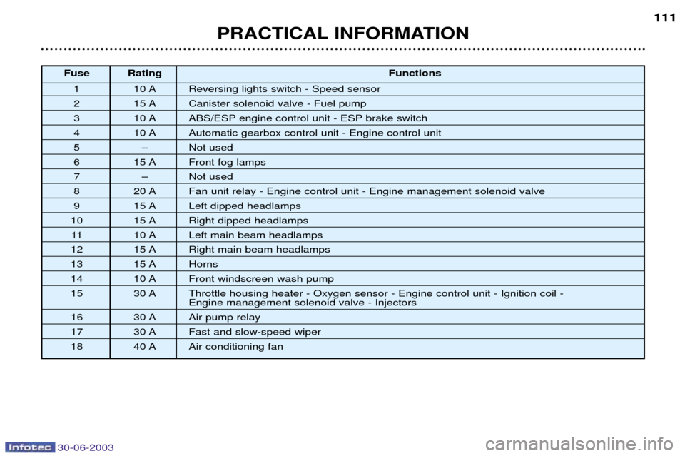
Fuse Rating
Functions
1 10 A Reversing lights switch - Speed sensor
2 15 A Canister solenoid valve - Fuel pump
3 10 A ABS/ESP engine control unit - ESP brake switch
4 10 A Automatic gearbox control unit - Engine control unit
5 Ð Not used
6 15 A Front fog lamps
7 Ð Not used
8 20 A Fan unit relay - Engine control unit - Engine management solenoid valve
9 15 A Left dipped headlamps
10 15 A Right dipped headlamps
11 10 A Left main beam headlamps
12 15 A Right main beam headlamps
13 15 A Horns
14 10 A Front windscreen wash pump
15 30 A Throttle housing heater - Oxygen sensor - Engine control unit - Ignition coil -
Engine management solenoid valve - Injectors
16 30 A Air pump relay
17 30 A Fast and slow-speed wiper
18 40 A Air conditioning fan
Page 120 of 135
30-06-2003
PRACTICAL INFORMATION
112
BATTERY
To charge the battery using a battery charger:
- Disconnect the battery,
- Follow the instructions for use given by the battery charger manufacturer,
- Reconnect starting with the negative (-) terminal,
- Check that the terminals and connectors are clean. If they are covered with
sulphate (white or greenish deposit), disconnect them and clean them.
To start the vehicle from another battery:
- Connect the red cable to the positive (+) terminals of the two batteries,
- Connect one end of the green or black cable to the negative (-) terminal of the slave battery,
- Connect the other end of the green or black cable to an earth point on the bro- ken down vehicle as far as possible from the battery,
Operate the starter, let the engine run.
Wait for the engine to return to idle, then disconnect the cables. ECONOMY MODE FUNCTION After the engine has stopped, with the key in the accessories position,
certain functions (windscreen wiper,electric windows, courtesy lights,audio equipment etc.) can only beused for thirty minutes, to prevent
discharging the battery.
Once the thirty minutes are over, the message
"Economy mode active"
appears on the multifunction displayand the active functions are put on
standby.
A flat battery will prevent the engine from starting.
- Wait for 2 minutes after switching off the ignition before disconnec- ting the battery.
- Never disconnect a terminal when the engine is running.
- Never charge a battery without first disconnecting the terminals.
- Close the windows and the folding roof before disconnecting the battery. If the windows do not operate normally following re-connection of the battery, you must re-initialise them (see section "Electric windows - ¤ Safety auto-reverse).
- After every reconnection of the battery, switch on the ignition and wait 1 minute before starting to allow the electronic systems to be initialised. If slight difficulties are experienced after this, please contact a PEUGEOT
dealer. It is advisable to disconnect the battery if the vehicle is not
to be used for a period of more than one month.