PONTIAC FIERO 1988 Service Repair Manual
Manufacturer: PONTIAC, Model Year: 1988, Model line: FIERO, Model: PONTIAC FIERO 1988Pages: 1825, PDF Size: 99.44 MB
Page 991 of 1825
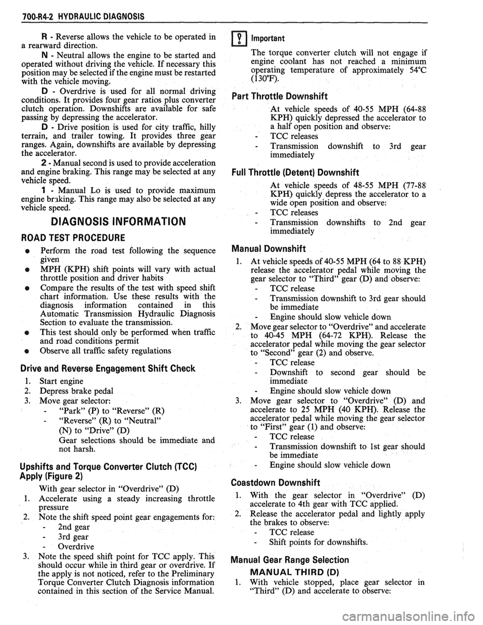
700-R4-2 HYDRAULIC DIAGNOSIS
R - Reverse allows the vehicle to be operated in
a rearward direction.
N - Neutral allows the engine to be started and
operated without driving the vehicle. If necessary this
position may be selected if the engine must be restarted
with the vehicle moving.
D - Overdrive is used for all normal driving
conditions. It provides four gear ratios plus converter
clutch operation. Downshifts are available for safe
passing by depressing the accelerator.
D - Drive position is used for city traffic, hilly
terrain, and trailer towing. It provides three gear
ranges. Again, downshifts are available by depressing
the accelerator.
2 - Manual second is used to provide acceleration
and engine braking. This range may be selected at any
vehicle speed.
1 - Manual Lo is used to provide maximum
engine
brlking. This range may also be selected at any
vehicle speed.
DIAGNOSIS INFORMATION
ROAD TEST PROCEDURE
e Perform the road test following the sequence
given
e MPH (KPH) shift points will vary with actual
throttle position and driver habits
e Compare the results of the test with speed shift
chart information. Use these results with the
diagnosis information contained in this
Automatic Transmission Hydraulic Diagnosis
Section to evaluate the transmission.
e This test should only be performed when traffic
and road conditions permit
e Observe all traffic safety regulations
Drive and Reverse Engagement Shift Check
1. Start engine
2. Depress brake pedal
3. Move gear selector:
- "Park" (P) to "Reverse" (R)
- "Reverse" (R) to "Neutral"
(N) to "Drive" (D)
Gear selections should be immediate and
not harsh.
Upshifts and Torque Converter Clutch (TCC)
Apply (Figure
2)
With gear selector in "Overdrive" (D)
1. Accelerate using a steady increasing throttle
pressure
2. Note the shift speed point gear engagements for:
- 2nd gear
- 3rd gear
- Overdrive
3. Note the speed shift point for TCC apply. This
should occur while in third gear or overdrive. If
the apply is not noticed, refer to the Preliminary
Torque Converter Clutch Diagnosis information
contained in this section of the Service Manual.
Important
The torque converter clutch will not engage if
engine coolant has not reached a minimum
operating temperature of approximately 54°C
(1 30°F).
Part Throttle Downshift
At vehicle speeds of 40-55 MPH (64-88
KPH) quickly depressed the accelerator to
a half open position and observe:
- TCC releases
- Transmission downshift to 3rd gear
immediately
Full Throttle (Detent) Downshift
At vehicle speeds of 48-55 MPH (77-88
KPH) quickly depress the accelerator to a
wide open position and observe:
- TCC releases
- Transmission downshifts to 2nd gear
immediately
Manual Downshift
1. At vehicle speeds of 40-55 MPH (64 to 88 KPH)
release the accelerator pedal while moving the
gear selector to "Third" gear (D) and observe:
- TCC release
- Transmission downshift to 3rd gear should
be immediate
- Engine should slow vehicle down
2. Move gear selector to "Overdrive" and accelerate
to 40-45 MPH (64-72 KPH). Release the
accelerator pedal while moving the gear selector
to "Second" gear (2) and observe.
- TCC release
- Downshift to second gear should be
immediate
- Engine should slow vehicle down
3. Move gear selector to "Overdrive" (D) and
accelerate to 25 MPH (40 KPH). Release the
accelerator pedal while moving the gear selector
to "First" gear (1) and observe:
- TCC release
- Transmission downshift to 1st gear should
be immediate
- Engine should slow vehicle down
Coastdown Downshift
1. With the gear selector in "Overdrive" (D)
accelerate to 4th gear with TCC applied.
2. Release the accelerator pedal and lightly apply
the brakes to observe:
- TCC release
- Shift points for downshifts.
Manual Gear Range Selection
MANUAL THIRD (D)
1. With vehicle stopped, place gear selector in
"Third" (D) and accelerate to observe:
Page 992 of 1825
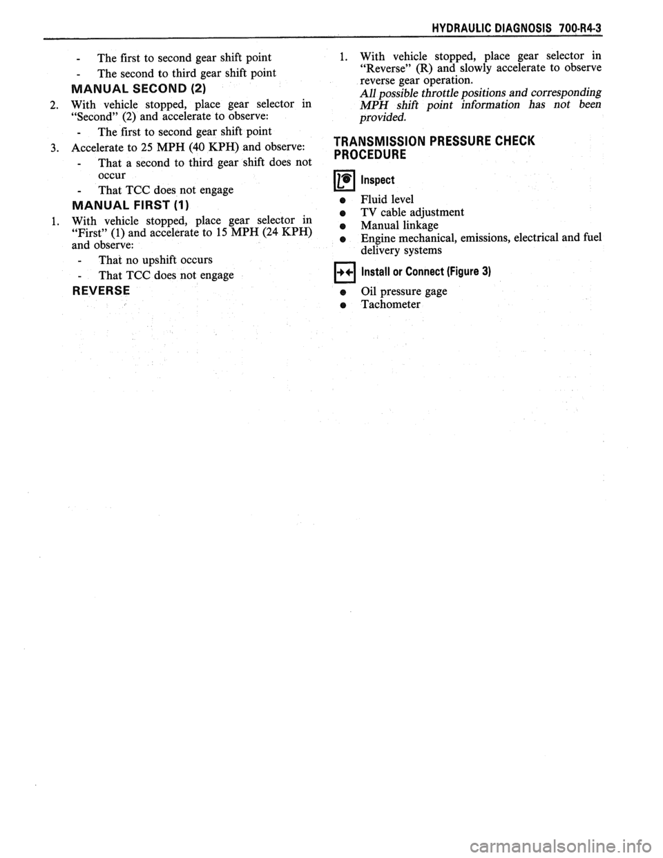
HYDRAULIC DIAGNOSIS 700434-3
- The first to second gear shift point
- The second to third gear shift point
MANUAL SECOND (2)
2. With vehicle stopped, place gear selector in
"Second" (2) and accelerate to observe:
- The first to second gear shift point
3. Accelerate to 25 MPH (40 KPH) and observe:
- That a second to third gear shift does not
occur
- That TCC does not engage
MANUAL FIRST (I)
1. With vehicle stopped, place gear selector in
"First" (1) and accelerate to 15 MPH (24
KPH)
and observe:
- That no uoshift occurs
- That TCC does
REVERSE
1. With
vehicle stopped, place gear selector in
"Reverse" (R) and slowly accelerate to observe
reverse gear operation.
All possible throttle positions and corresponding
MPH shift point information has not been
provided.
TRANSMISSION PRESSURE CHECK
PROCEDURE
Inspect
e Fluid level
e TV cable adjustment
e Manual linkage
e Engine mechanical, emissions, electrical and fuel
delivery systems
not engage
Install or Connect (Figure 3)
a Oil pressure gage
a Tachometer
Page 993 of 1825
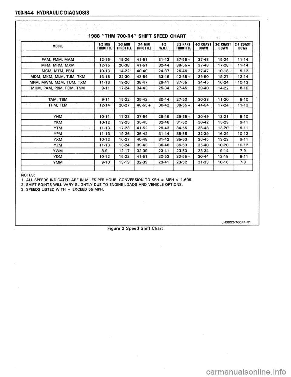
700-R4.4 HYDRAULIC DIAGNOSIS
1988 "THM 700-R4" SHIFT SPEED CHART
NOTES: 1. ALL SPEEDS INDICATED ARE IN MILES PER HOUR. CONVERSION TO KPH = MPH x 1.609.
2.
SHIFT POINTS WILL VARY SLIGHTLY DUE TO ENGINE LOADS AND VEHICLE OPTIONS. 3. SPEEDS LISTED WITH + EXCEED 55 MPH.
Figure 2 Speed Shift Chart
Page 994 of 1825
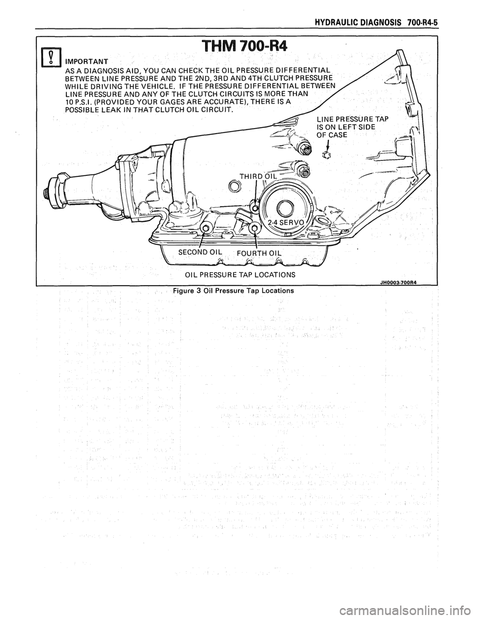
HYDRAULIC DIAGNOSIS 700-R4-5
AS A DIAGNOSIS AID, YOU CAN CHECK THE OIL PRESSU BETWEEN LINE PRESSURE AND THE 2ND, 3RD AND 4TH
WHILE DRIVING THE VEHICLE. IF THE PRESSURE
DIFF
LINE PRESSURE TAP
IS ON LEFT
SIDE
Figure 3 Oil Pressure Tap Locations
Page 995 of 1825
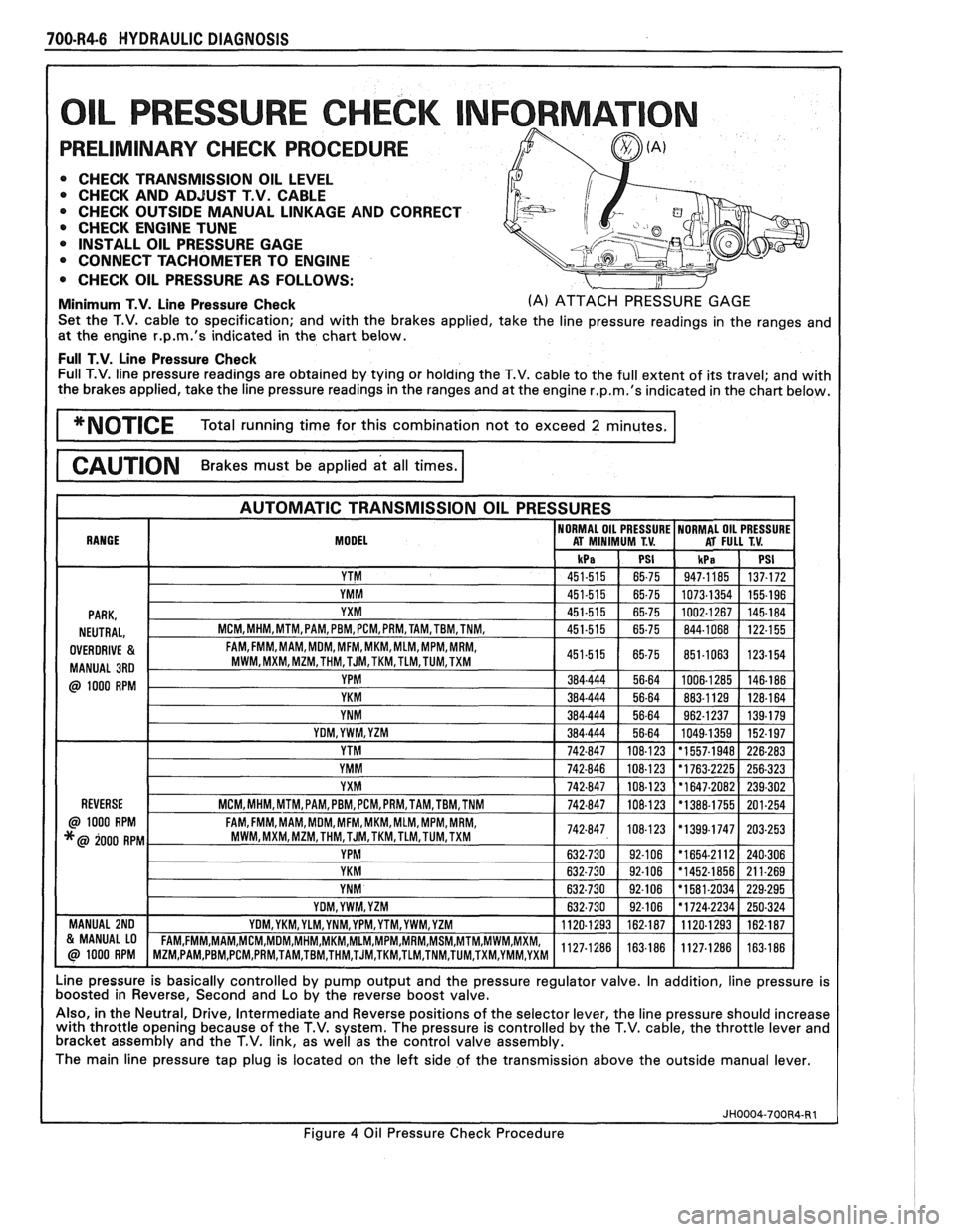
700-R4-6 HYDRAULIC DIAGNOSIS
L PRESSURE CHECK NFORMAT
PRELIMINARY CHECK PROCEDURE
0 CHECK TRANSMISSION OIL LEVEL 0 CHECK AND ADJUST T.V. CABLE
0 CHECK OUTSIDE MANUAL LINKAGE AND CORRECT
@ CHECK ENGINE TUNE
0 INSTALL OIL PRESSURE GAGE
CONNECT TACHOMETER TO ENGINE
0 CHECK OIL PRESSURE AS FOLLOWS:
Minimum T.V. Line Pressure Check (A) ATTACH PRESSURE GAGE
Set the T.V. cable to specification; and with the brakes applied, take the line pressure readings in the ranges and
at the engine
r.p.m.'s indicated in the chart below.
Full T.V. Line Pressure Check Full T.V. line pressure readings are obtained by tying or holding the T.V. cable to the full extent of its travel; and with
the brakes applied, take the line pressure readings in the ranges and at the engine
r.p.m.'s indicated in the chart below.
MODEL
Line pressure is basically controlled by pump output and the pressure regulator valve. In addition, line pressure is
boosted in Reverse, Second and Lo by the reverse boost valve.
Also, in the Neutral, Drive, Intermediate and Reverse positions of the selector lever, the line pressure should increase
with throttle opening because of the T.V. system. The pressure is controlled by the T.V. cable, the throttle lever and
bracket assembly and the T.V. link, as well as the control valve assembly.
The main line pressure tap plug is located on the left side of the transmission above the outside manual lever.
Figure
4 Oil Pressure Check Procedure
Page 996 of 1825
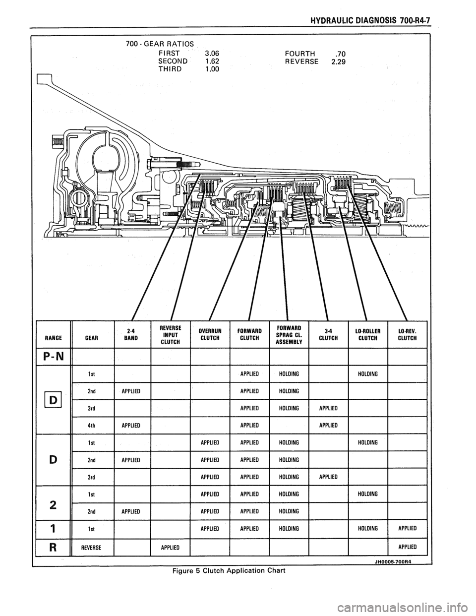
HYDRAULIC DIAGNOSIS 700-R4-7
SECOND 1.62 REVERSE 2.29 THIRD 1 .OO
Figure 5 Clutch Application Chart
Page 997 of 1825
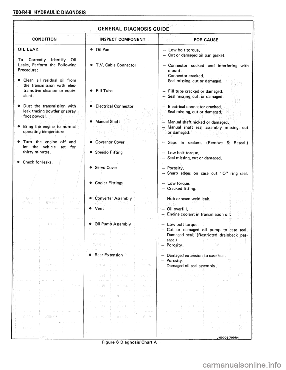
700-R4-8 HYDRAULIC DIAGNOSIS
OIL LEAK - Low bolt torque.
- Cut or damaged oil pan gasket.
To Correctly Identify Oil
Leaks, Perform the Following
T.V. Cable Connector - Connector cocked and interfering with
Procedure:
- Connector cracked.
0 Clean all residual oil from - Seal missing, cut or damaged.
the transmission with
elec-
tramotive cleanser or equiv- - Fill tube cracked or damaged.
alent.
- Seal missing, cut, or damaged.
0 Dust the transmission with 0 Electrical Connector - Electrical connector cracked.
leak tracing powder or spray
- Seal missing, cut or damaged.
foot powder.
@ Manual Shaft - Manual shaft nicked or damaged.
Bring the engine to normal
- Manual shaft seal assembly missing, cut
operating temperature.
Turn the engine off and Governor Cover
- Gaps in sealant. (Remove & Reseal.)
let the vehicle set for
Speedo Fitting
- Low bolt torque.
- Seal missing, cut or damaged.
Check for leaks.
@ Servo Cover
Cooler Fittings
- Cracked fitting.
0 Converter Assembly - Hub or seam weld leak.
- Oil overfill.
- Engine coolant in transmissio
0 Oil Pump Assembly
Rear Extension
- Damaged extension to case seal.
Figure
6 Diagnosis Chart A
Page 998 of 1825
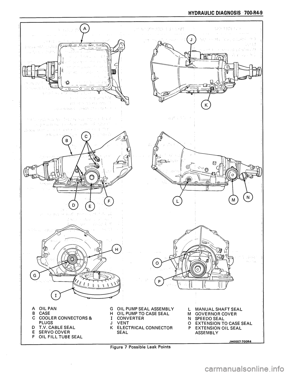
HYDRAULIC DIAGNOSIS 700-R4-9
A OILPAN G OIL PUMP SEAL ASSEMBLY L MANUAL SHAFT SEAL
B CASE
H OIL PUMP TO CASE SEAL M GOVERNOR COVER
C COOLER CONNECTORS
& 1 CONVERTER
N SPEEDOSEAL
PLUGS J VENT 0 EXTENSION TO CASE SEAL
D T.V. CABLE SEAL
K ELECTRICAL CONNECTOR P EXTENSION OIL SEAL
E SERVO COVER SEAL ASSEMBLY
F OIL FILL TUBE SEAL
Figure
7 Possible Leak Points
Page 999 of 1825
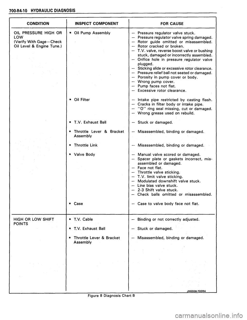
100.R4.10 HYDRAULIC DIAGNOSIS
(Verify With Gage-Check - Rotor guide omitted or misassembled.
Oil Level
81 Engine Tune.) - Rotor cracked or broken. - T.V. valve, reverse boost valve or bushing
stuck, damaged or incorrectly assembled.
- Orifice hole in pressure regulator valve
- Sticking slide or excessive rotor clearance.
- Pressure relief ball not seated or damaged.
- Porosity in pump cover or body.
- Wrong pump cover.
- Pump faces not flat.
- Excessive rotor clearance.
- Intake pipe restricted by casting flash.
- Cracks in filter body or intake pipe.
- "0" ring seal missing, cut or damaged.
- Wrong grease used on rebuild.
T.V. Exhaust Ball
- Stuck or damaged.
* Throttle Link - Misassembled, binding or damaged.
- Manual valve scored or damaged.
- Spacer plate or gaskets incorrect, mis-
assembled or damaged.
- Face not flat.
- Throttle valve sticking.
- T.V. limit valve sticking.
- Modulated downshift valve stuck.
- Line bias valve stuck.
- 2-3 Shift valve stuck.
- Check balls omitted or misassembled.
- Case to valve body face not flat.
T.V. Exhaust Ball
- Stuck or damaged.
Throttle Lever
81 Bracket - Misassembled, binding or damaged.
Figure
8 Diagnosis Chart B
Page 1000 of 1825
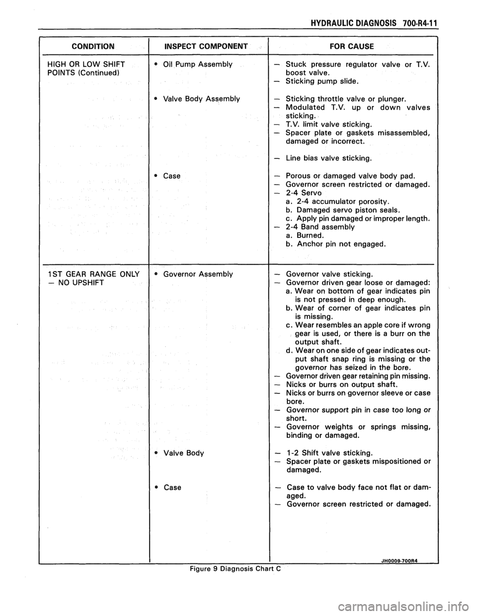
HYDRAULIC DIAGNOSIS 700-R4-I 1
CONDITION I INSPECT COMPONENT
HIGH OR LOW SHIFT
POINTS (Continued) 0 Oil Pump Assembly
0 Valve Body Assembly
Case
Valve Body
- Stuck pressure regulator valve or T.V.
boost valve.
- Sticking pump slide.
- Sticking throttle valve or plunger.
- Modulated T.V. up or down valves
sticking.
- T.V. limit valve sticking. - Spacer plate or gaskets misassembled,
damaged or incorrect.
I - Line bias valve sticking.
- Porous or damaged valve body pad.
- Governor screen restricted or damaged.
- 2-4 Servo
a. 2-4 accumulator porosity.
b. Damaged servo piston seals.
c. Apply pin damaged or improper length.
- 2-4 Band assembly
a. Burned.
b. Anchor pin not engaged.
- Governor valve sticking. - Governor driven gear loose or damaged:
a. Wear on bottom of gear indicates pin
is not pressed in deep enough.
b. Wear of corner of gear indicates pin
is missing.
c. Wear resembles an apple core if wrong
gear is used, or there is a burr on the
output shaft.
d. Wear on one side of gear indicates out-
put shaft snap ring is missing or the
governor has seized in the bore.
- Governor driven gear retaining pin missing.
- Nicks or burrs on output shaft.
- Nicks or burrs on governor sleeve or case
bore.
- Governor support pin in case too long or
short.
- Governor weights or springs missing,
binding or damaged.
- 1-2 Shift valve sticking. - Spacer plate or gaskets mispositioned or
damaged.
- Case to valve body face not flat or dam-
aged.
- Governor screen restricted or damaged.
Figure 9 Diagnosis Chart C