PONTIAC FIERO 1988 Service Repair Manual
Manufacturer: PONTIAC, Model Year: 1988, Model line: FIERO, Model: PONTIAC FIERO 1988Pages: 1825, PDF Size: 99.44 MB
Page 1171 of 1825
INTRODUCTION
COMPONENT LOCATIONS
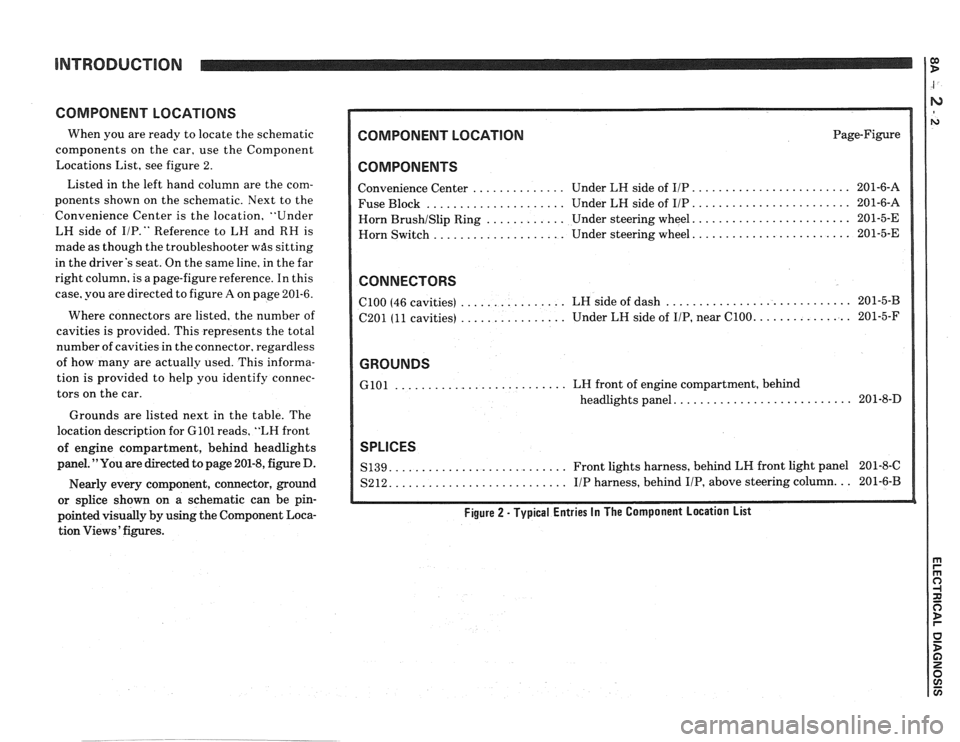
When you are ready to locate the schematic
components on the car, use the Component
Locations List, see figure 2.
Listed in the left hand column are the com-
ponents shown on the schematic. Next to the
Convenience Center is the location, "Under
LH side of
I/P." Reference to LH and RH is
made as though the troubleshooter
was sitting
in the driver's seat. On the same line, in the far
right column, is a page-figure reference. In this
case, you are directed to figure
A on page 201-6.
Where connectors are listed, the number of
cavities is provided. This represents the total
number of cavities in the connector, regardless
of how many are actually used. This informa-
tion is provided to help you identify connec-
tors on the car.
Grounds are listed next in the table. The
location description for
GlOl reads, "LH front
of engine compartment, behind headlights
panel. "You are directed to page 201-8, figure D.
Nearly every component, connector, ground
or splice shown on a schematic can be pin-
pointed visually by using the Component Loca-
tion Views' figures.
COMPONENT LOCATION Page-Figure
COMPONENTS
........................ Convenience Center .............. Under LH side of IIP 201-6-A
..................... ........................ Fuse Block Under LH side of IIP 201-6-A
....................... Horn BrushISlip Ring ............ Under steering wheel. 201-5-E
....................... Horn
Switch .................... Under steering wheel. 201-5-E
CONNECTORS
............................ ................ ClOO (46 cavities)
LH side of dash 201-5-B
................ .............. C201 (11 cavities) Under
LH side of IIP, near C100. 201-5-F
GROUNDS
.......................... GlOl LH front of engine compartment, behind
.......................... headlights panel. 201-8-D
SPLICES
.......................... S139. Front lights harness, behind LH front light panel 201-8-C
.......................... S212. IIP harness, behind IIP, above steering column. .. 201-6-B
Figure 2 - Typical Entries In The Component Location List
Page 1172 of 1825
INTRODUCTION
HARNESS CONNECTOR FACES
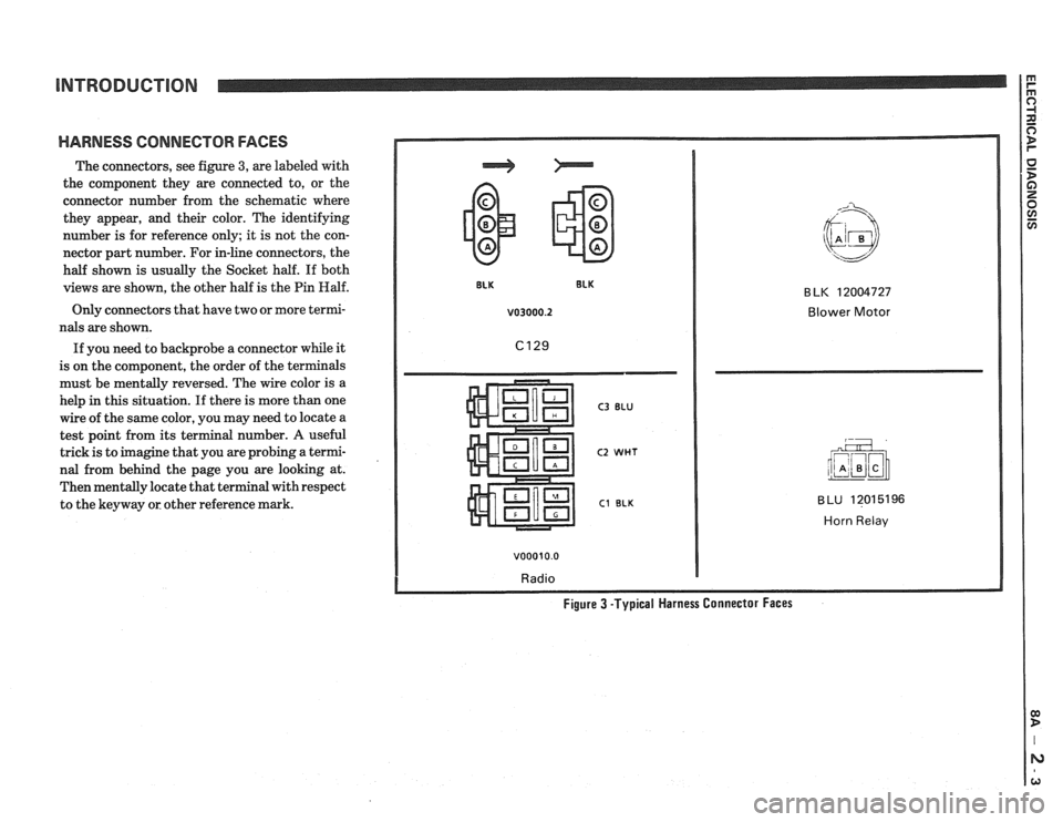
The connectors, see figure 3, are labeled with
the component they are connected to, or the
connector number from the schematic where
they appear, and their color. The identifying
number is for reference only; it is not the con-
nector part number. For in-line connectors, the
half shown is usually the Socket half. If both
views are shown, the other half is the Pin
Half.
Only connectors that have two or more termi-
nals are shown.
If you need to backprobe a connector while it
is on the component, the order of the terminals
must be mentally reversed. The wire color is a
help
in this situation. If there is more than one
wire of the same color, you may need to locate a
test point from its terminal number.
A useful
trick is to imagine that you are probing a termi-
nal from behind the page you are looking at.
Then mentally locate that terminal with respect
to the keyway or other reference mark.
v03000.2 Blower Motor
C3 BLU
C2 WHT
C1 BLK
v00010.0
Radio
BLU 12015196
Horn Relav
Figure 3 -Typical Harness Connector Faces
Page 1173 of 1825
INTRODUCTION
OTHER INFORNlATlORl
Body Part Names
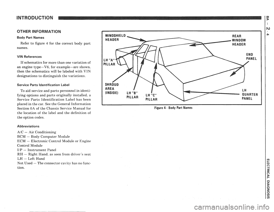
Refer to figure 4 for the correct body part
names.
VIN References
If schematics for more than one variation of
an engine type-V6, for example--are shown,
then the schematics will be labeled with VIN
designations to distinguish the variations.
Service Parts Identification Label
To aid service and parts personnel in identi-
fying options and parts originally installed. a
Service Parts Identification Label has been
REAR
PANEL
placed in the car. See the General Information
Section OA of the Chassis Service Manual for
Figure 4 - Body Part Names
the location of the label and the definition of
the option codes.
Abbreviations
AIC - Air Conditioning
BCbl - Body Computer Module
ECM
- Electronic Control Module or Engine
Control Module
IIP
- Instrument Panel
RH
- Right Hand. as seen from driver's seat
LH
- Left Hand
Not Used
- The connector cavity has no func-
tion.
Page 1174 of 1825
INTRODUCTION
Power Distribution
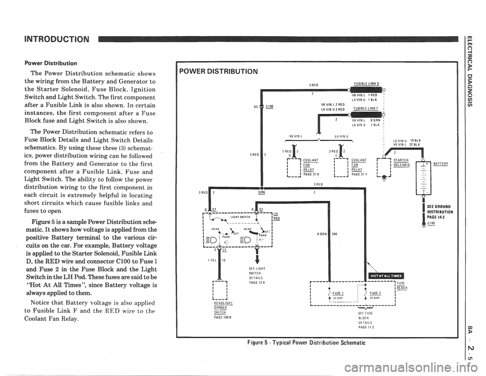
The Power Distribution schematic shows
the wiring from the Battery and Generator to
the Starter Solenoid, Fuse Block, Ignition
Switch and Light Switch. The first component
after a Fusible Link is also shown. In certain
instances, the first component after a Fuse
Block fuse and Light Switch is also shown.
The Power Distribution schematic refers to
Fuse Block Details and Light Switch Details
schematics. By using these three
(3) schemat-
ics, power distribution wiring can be followed
from the Battery and Generator to the first
component after a Fusible Link. Fuse and
Light Switch. The ability to follow the power
distribution wiring to the first component in
each circuit is extremely helpful in locating
short circuits which cause fusible links and
fuses to open.
Figure
5 is a sample Power Distribution sche-
matic.
It shows how voltage is applied from the
positive Battery terminal to the various cir-
cuits on the car. For example, Battery voltage
is applied to the Starter Solenoid, Fusible Link
D, the
RED wire and connector ClOO to Fuse 1
and Fuse 2 in the Fuse Block and the Light
Switch in the
LH Pod. These fuses are said to be
"Not At All Times", since Battery voltage is
always applied to them.
Notice that Battery voltage is
also applied
to Fusible Link
F and the RED wire to the
Coolant Fan Relay.
L4VIN U 1 ELK I
i VSVIN L 32 BLK
DISTRIBUTION
SkE LIGHT
HEADLIGHT
--
PAGE 100 0 BLOCK DETAILS PAGE 11 2
Figure 5 -Typical Power Distribution Schematic
Page 1175 of 1825
INTRODUCTION
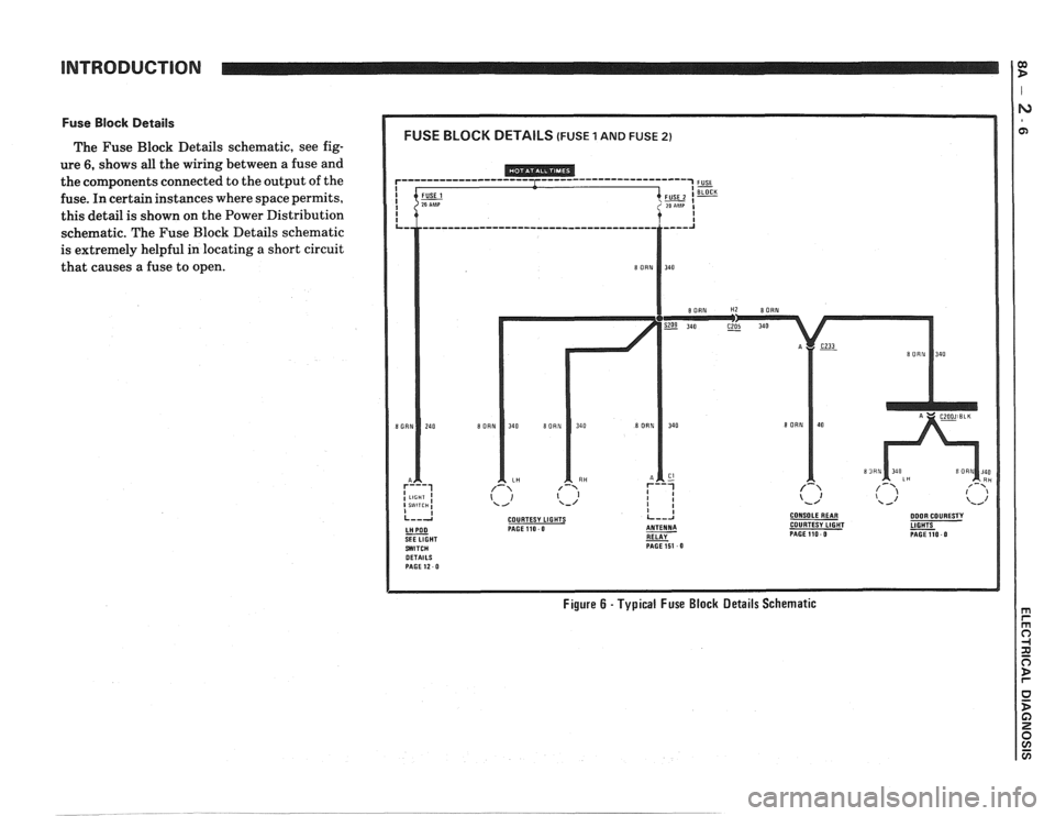
Fuse Block Details
The Fuse Block Details schematic, see fig-
ure
6, shows all the wiring between a fuse and
the components connected to the output of the
fuse. In certain instances where space permits,
this detail is shown on the Power Distribution
schematic. The Fuse Block Details schematic
is extremely helpful in locating
a short circuit
that causes a fuse to open.
COURTESY LIGHTS CONSOLEREAR DOOR COURESTY PAGE110 0 COURTESY LIGHT
RELAY - PAGEllO 0 PAGE151 0
Figure 6 - Typical Fuse Block Details Schematic
Page 1176 of 1825
INTRODUCTION
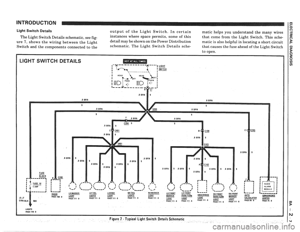
Light Switch Details output of the Light Switch. In certain matic helps you understand the many wires
The Light Switch Details schematic, see
fig- instances where space permits, some of this
that come from the Light Switch. This sche-
ure 7, shows the wiring between the Light detail
may be shown on the Power Distribution matic is also helpful in locating a short circuit
Switch and the components connected to the schematic.
The Light Switch Details
sche- that causes the fuse ahead of the Light Switch
to open.
LIGHT SWITCH DETAILS ,' '6--- ----- --- 5""l LIGHT
Page 1177 of 1825
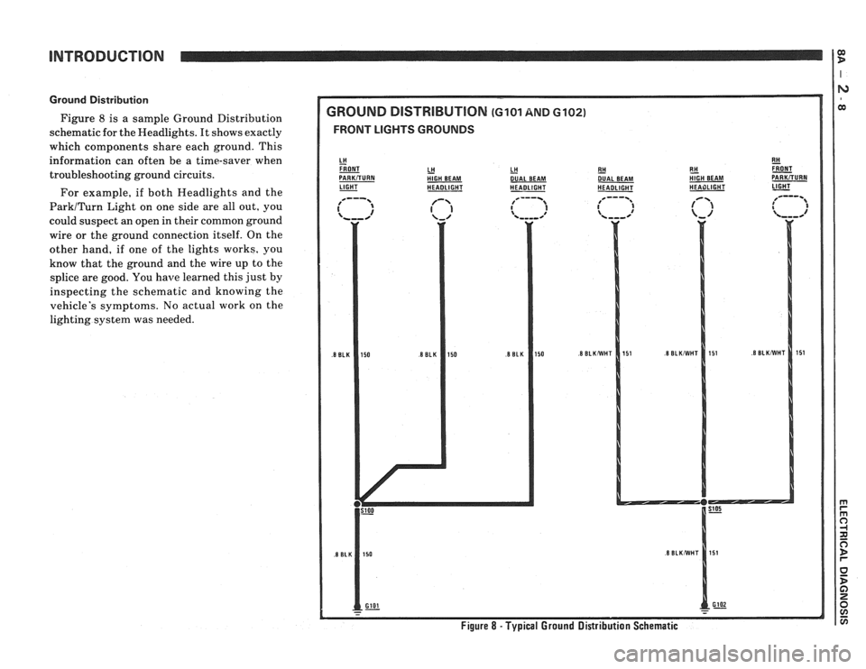
Ground Distribution
Figure 8 is a sample Ground Distribution
schematic for the Headlights. It shows exactly
which compcments share each ground. This
information can often be a time-saver when
troubleshooting ground circuits.
For example, if both Headlights and the
ParkITurn Light on one side are all out, you
could suspect an open in their common ground
wire or the ground connection itself. On the
other hand, if one of the lights works, you
know that the ground and the wire up to the
splice are good. You
have learned this just by
inspecting the schematic and knowing the
vehicle's symptoms. No actual work on the
lighting system was needed.
GROUND DlSTRlBUTlON (GI01 AND 6102)
FRONT LIGHTS GROUNDS
LH HlGH BEAM LH - DUAL
BEAM
LIGHT - HEADLIGHT HEADLIGHT RH
- DUAL
BEAM
HEADLIGHT E!! &T HIGH BEAM PARKiTURN HEAilLlGHT 1-
Figure 8 - Typical Ground Distribution Schematic
Page 1178 of 1825
ENTIRE
COMPONENT
SHOWN
PART OF A
COMPONENT
SHOWN
NAME OF
COMPONENT
OPERATION COMPONENT
CASE IS
DIRECTLY ATTACHEOTO
- METAL PART
OF CAR
(GROUNOEO)
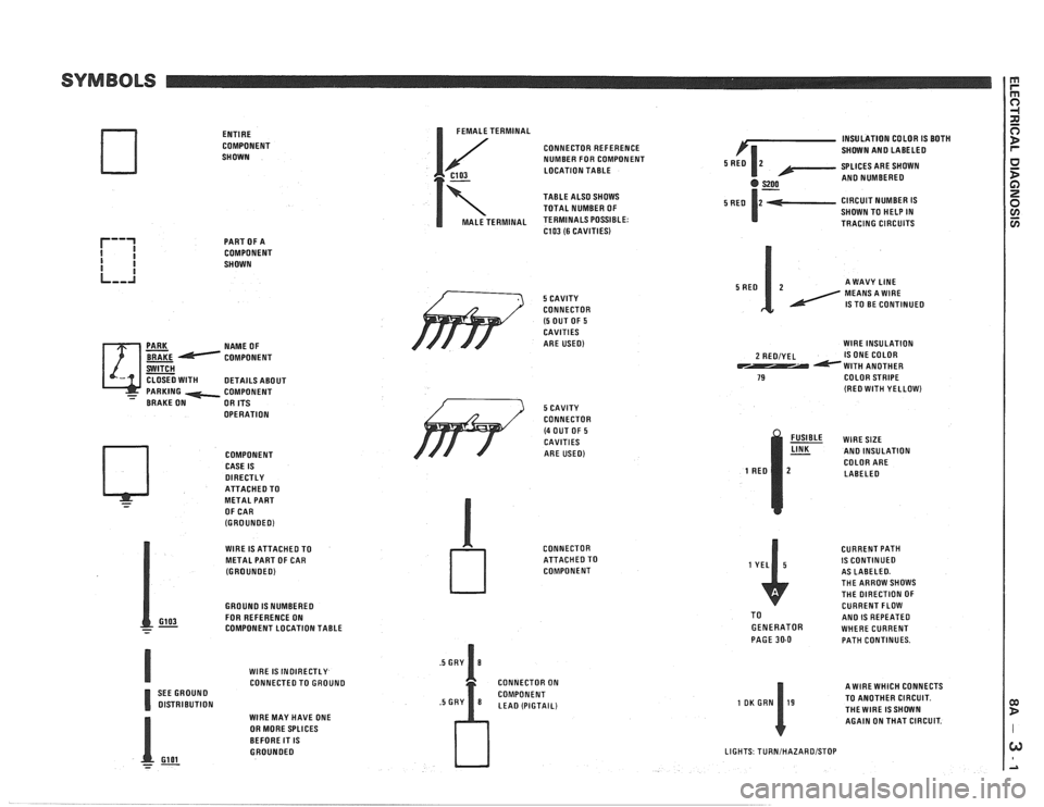
I FEMALE TERMINAL
CONNECTOR REFERENCE
NUMBER FOR COMPONENT
C103 LOCATION TABLE
7
TABLE ALSO SHOWS
TOTAL NUMBER OF
MALE TERMINAL TERMINALS POSSIBLE: C103 (6 CAVITIES)
/' 5 CAVITY
CONNECTOR
(5 OUT OF 5 CAVITIES
ARE USED)
WlRE IS ATTACHED TO
METAL PART OF CAR
(GROUNOEO)
GROUNO
IS NUMBEREO
GI03 FOR REFERENCE ON - - - COMPONENT LOCATION TABLE
WlRE
IS INOIRECTLY CONNECTED TO GROUNO
SEE GROUNO
OlSTRlBUTlON WlRE MAY HAVE ONE
OR MORE SPLICES
BEFORE IT
IS GROUNOEO
- Gl 01 --
/ 3 5 CAVITY
CONNECTOR
(4 OUT OF 5 CAVITIES
ARE USED)
CONNECTOR
ATTACHEOTO
COMPONENT
CONNECTOR ON
COMPONENT
LEA0 (PIGTAIL) INSULATION
COLOR
IS BOTH
SHOWN AN0 LABELEO
SPLICES ARE SHOWN
AN0 NUMBEREO
CIRCUIT NUMBER
IS SHOWN TO HELP IN
TRACING CIRCUITS
A WAVY
LINE MEANS A WlRE IS TO BE CONTINUED
WlRE INSULATION
2 REOIYEL IS ONE COLOR WlTH ANOTHER 79 COLOR STRIPE (RE0 WlTH YELLOW)
% WIRESIZE AN0 INSULATION
COLOR ARE
LABELEO
CURRENT PATH
IS CONTINUED
AS LABELEO.
THE ARROW SHOWS
THE DIRECTION OF
CURRENT FLOW
TO
AN0 IS REPEATED GENERATOR WHERE CURRENT
PAGE 30-0 PATH CONTINUES.
A WlRE WHICH CONNECTS
TO ANOTHER CIRCUIT.
THEWIRE ISSHOWN AGAIN ON THAT CIRCUIT.
LIGHTS TURNIHAZAROISTOP
Page 1179 of 1825
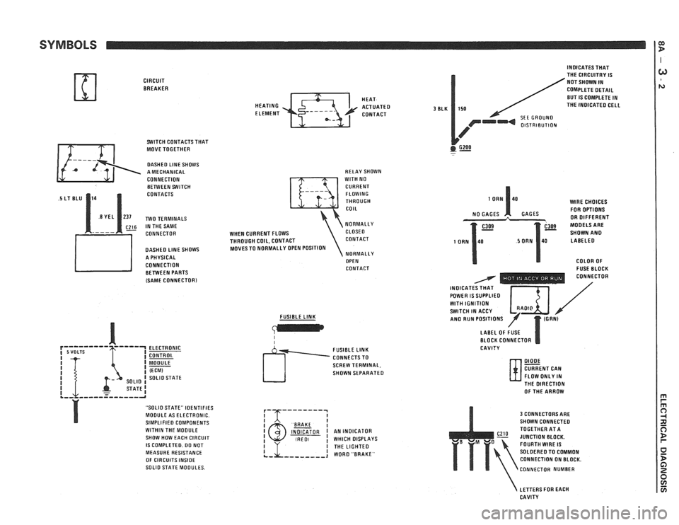
SYMBOLS
CIRCUIT BREAKER
SWITCH CONTACTS THAT
MOVE TOGETHER
DASHED LlNE SHOWS
A MECHANICAL
CONNECTION BETWEEN SWITCH
CONTACTS
~26 IN THE SAME
CONNECTOR
DASHED
LlNE SHOWS
A PHYSICAL
CONNECTION BETWEEN PARTS
(SAME
CONNECTORl
ELECTRONIC
CONTROL
MODULE
(ECM) SOLlO STATE
STATE1 .,, ,,,--=----,-a
"SOLIO STATE" IDENTIFIES
MODULE AS ELECTRONIC.
SIMPLIFIED COMPONENTS
WITHIN THE MOOULE
SHOW HOW EACH CIRCUIT
IS COMPLETED. DO NOT
MEASURE RESISTANCE
OF CIRCUITS
INSIDE SOLlO STATE MODULES. HEAT
HEATING
ACTUATED ELEMENT CONTACT
RELAY SHOWN
WlTH NO
CURRENT FLOWING
THROUGH
COIL
NORMALLY
WHEN CURRENT FLOWS CLOSE0
THROUGH COIL, CONTACT CONTACT
MOVES TO NORMALLY OPEN POSITION
NORMALLY
OPEN
CONTACT
FUSIBLE
LINK
I I
SCREW TERMINAL,
SHOWN SEPARATED
I BAAKE I INDICATOR I AN INDICATOR (RED, ! WHICH DISPLAYS
3 BLK
INDICATES THAT
THE CIRCUITRY IS
NOT SHOWN IN
COMPLETE DETAIL
BUT
IS COMPLETE IN
150 THE INOICATED CELL
SEE GROUND OlSTRlBUTlON
GZOO . -
WlRE CHOICES
FOR OPTIONS
GAGES OR DIFFERENT
SHOWN
AN0 LABELED
COLOR OF
- FUSE BLOCK - - - - - - - . . CONNECTOR
INOICAT / POWER IS SUPPLIED I $ I / WlTH IGNITION SWITCH IN ACCY /' AN0 RUN POSITIONS
LABEL OF FUSE
BLOCK CONNECTOR
CAVITY
DIODE CURRENT CAN
FLOW ONLY IN
N- THE DIRECTION
OF THE ARROW
3 CONNECTORS ARE
SHOWN CONNECTED
TOGETHER AT A
JUNCTION BLOCK.
FOURTH
WIRE IS
SOLDERED TO COMMON
CONNECTION ON BLOCK.
CONNECTOR NUMBER
LETTERS FOR EACH
CAVITY
Page 1180 of 1825
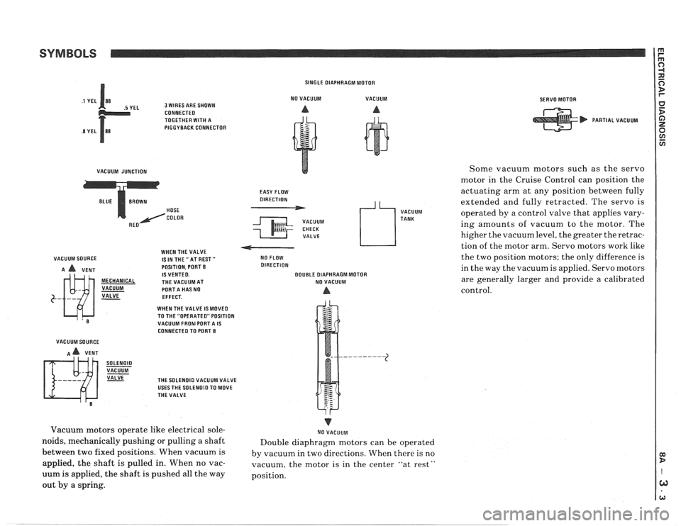
SYMBOLS
EL 3 WIRES ARE SHOWN
CONNECTEO
TOGETHER WITH A
PIGGYBACK CONNECTOR
VACUUM JUNCTION HOSE
COLOR
VACUUM SOURCE WHEN
THE VALVE
1SINTHE"ATREST"
A A VENT POSITION.
PORT B IS VENTED. MECHANICAL THE VACUUM AT
VACUUM PORTA HAS NO
VALVE
- EFFECT.
WHEN THE VALVE IS
MOVED
VACUUM SOURCE
A A VENT
SOLENOID VACUUM VALVE
TO THE "OPERATED" POSITION
VACUUM FROhl PORTA IS CONNECTEO TO PORT B
THE SOLENOID VACUUM VALVE
USES THE SOLENOID TO MOVE
THE VALVE SINGLE
DIAPHRAGM MOTOR
NO VACUUM VACUUM
A A
EASY FLOW
DIRECTION
VACUUM CHECK VALVE
4 L, VACUUM
TANK
NO FLOW
DIRECTION
DOUBLE DIAPHRAGM MOTOR
NO VACUUM
A
Vacuum motors operate like electrical sole-
noids, mechanically pushing or pulling a shaft
between two fixed positions. When vacuum is
applied, the shaft is pulled in. When no vac-
uum is applied, the shaft is pushed all the way
out by a spring. I
NO VACUUM
Double diaphragm motors can be operated
by vacuum in two directions. When there is no
vacuum, the motor is in the center "at rest"
position.
SERVO MOTOR
PARTIAL VACUUM
Some vacuum motors such as the servo
motor in the Cruise Control can
posit,ion the
actuating arm at any position between fully
extended and fully retracted. The servo is
operated by a control valve that applies vary-
ing amounts of vacuum to the motor. The
higher the vacuum level, the greater the retrac-
tion of the motor arm. Servo motors work like
the two position motors; the only difference is
in the way the vacuum is applied. Servo motors
are generally larger and provide a calibrated
control.