PONTIAC FIERO 1988 Service Repair Manual
Manufacturer: PONTIAC, Model Year: 1988, Model line: FIERO, Model: PONTIAC FIERO 1988Pages: 1825, PDF Size: 99.44 MB
Page 1181 of 1825
TROUBLESHOOTING PROCEDURES
The following four-step troubleshooting pro-
cedure is recommended:
Step 1: Check the problem.
Perform a System Check to be sure you
understand what's wrong. Don't waste time
fixing part of the problem! Do not begin dis-
assembly or testing until you have narrowed
down the possible causes.
Step 2: Read the Electrical Schematic.
Study the schematic. Read the Circuit Oper-
ation text if you do not understand how the
circuit
should work. Check circuits that share
wiring with the problem circuit. The names of
circuits that share the same fuse, ground,
switch, etc., are included on each electrical
schematic. (Shared circuits are also shown on
Power Distribution, Ground Distribution,
Fuse Block Details, and Light Switch pages.)
Try to operate the shared circuits. If the
shared circuits work, then the shared wiring is
OK. The cause must be within the wiring used
only by the problem circuit. If several circuits
fail at the same time, chances are the power
(fuse) or ground circuit is faulty.
Step 3: Find the Cause and Repair.
* Narrow down the possible causes.
@ Use the Troubleshooting Hints.
@ Make the necessary measurements as
given in the System Diagnosis.
Step 4: Test the Repair
Repeat the System Check to be sure you
have fixed the whole problem.
Example
A customer brings in a car and says that the
high beams do not work.
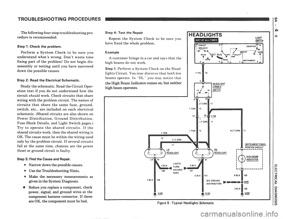
Step 1: Perform a System Check on the Head-
lights Circuit. You may discover that both low
beams operate. In
"Hi," you may notice that
the High Beam Indicator comes on, but neither
high beam operates.
INSTRUMENT PANEL PRINTED CIRCUIT
DISTRIBUTION
@ Before you replace a component, check
power, signal, and ground wires at the
component harness connector. If these
are
OK, the component must be bad. Figure 9 - Typical Headlights Schematic
Page 1182 of 1825
TROUBLESHOOTING PROCEDURES
Step 2: Read the Headlights electrical sche-
matic, see figure
9. This is the step that will
save you time and labor. Remember, it is
essential to understand how a circuit
should
work, before trying to figure out why it
doesn't.
After you understand how the circuit should
operate, read the schematic again, this time
keeping in mind what you have learned by
operating the circuit.
Since both low beams work. you know that
the
Light Switch. the YEI, wire. the I,o con-
tacts of the Headlight Dimmer Switch. termi-
nal
1E of C100. the TAN wires. and grounds
6105 and G 109 are all good.
Furthermore, since you saw that the High
Beam Indicator came on when the Headlight
Dimmer Switch was moved to Hi. you know
that the Hi contacts of the
dimmer switch and
the
I,T GRN wire between the dimmer switch
and ClOO are good.
At this point. you could test for
voltage at
the RH Headlight with the dimmer switch in
Hi. However. it is extremely unlikely that the
high beam filaments have burned out in
both
headlights. or that both headlight connections
are bad. The cause must be a bad connection at
C100, or a break in the I,T GRN wire between
ClOO and the RH Headlight.
I,T GRN wire, locate the exact trouble point,
and make the repair.
Step 4: Check the repair by performing a sys-
tem check on the Headlights circuit. This, of
course, means making sure that both high
beams, both low beams, and the High Beam
Indicator are all working.
Now suppose that the symptoms were dif-
ferent. You may have operated the Headlights
and found that the low beams were working,
but neither the high beams nor the High Beam
Indicator were working. Looking at the sche-
matic, you might conclude the
following.
It is unlikely that both high beam filaments
and the High Beam Indicator have all burned
out at once. The cause is probably the dimmer
switch or its connector.
You have quickly narrowed the possible
causes down to one specific area, and have
done absolutely
no work on the car itself.
Step 3: Find the cause and repair it. Using the
Component Location List and the correspond-
ing figure. you can quickly find ClOO and the
Page 1183 of 1825
TROUBLESHOOT1NG TOOLS
Electrical troubleshooting requires the use
of common electrical test equipment.
TEST LIGHTIVOLTMETER
Use a test light to check for voltage. A Test
Light (BT-7905 or equivalent) is made up of a
12-Volt light bulb with apair of leads attached.
After grounding one lead, touch the other lead
to various points along the circuit where volt-
age should be present. When the bulb goes on,
there is voltage at the point being tested.
A voltmeter can be used instead of a test
light. While a test light shows whether or not
voltage is present, a voltmeter indicates how
much voltage is present.
An increasing number of circuits include
solid state control modules. One example is the
Electronic Control Module
(ECM) used with
Computer Command Control and Electronic
Fuel Injection. Voltages in these circuits
should be tested only with a 10-megohm or
higher impedance digital voltmeter or multi-
meter (5-29125 or equivalent). Never use a test
light on circuits that contain solid state compo-
nents, since damage to these components may
result.
When testing for voltage or continuity at a
connection, you do not have to separate the
two halves of the connector. Unless you are
testing a "weather-pack" connector, you
should probe the connector from the back.
Always check both sides of the connector. An
accumulation of dirt and corrosion between
contact surfaces is sometimes a cause of elec-
trical problems.
CONNECTOR TEST ADAPTERS
A connector Adapter Kit is available
(535616) for making tests and measurements at
separated connectors. This kit contains an
assortment of probes which mate with many of
the types of connectors you will see. Avoid
using paper clips and other substitutes since
they can damage terminals and cause incorrect
measurements.
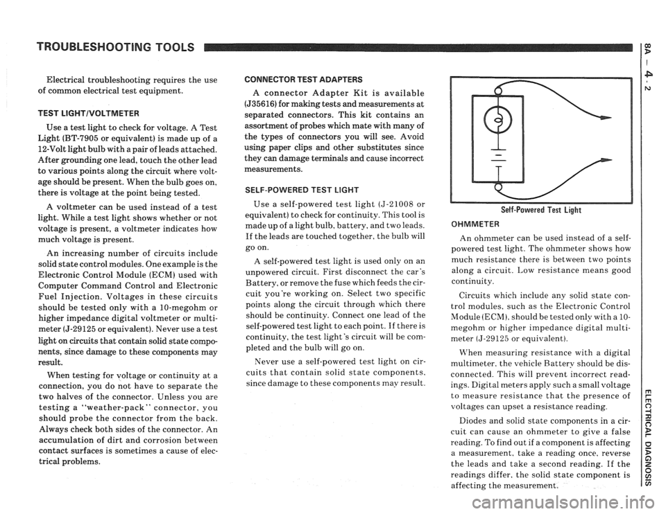
SELF-POWERED TEST LIGHT
Use a self-powered test light (5-21008 or
equivalent) to check for continuity. This tool is
made up of a light bulb, battery, and two leads.
If the leads are touched together, the bulb will
go on.
A self-powered test light is used only on an
unpowered circuit. First disconnect the car's
Battery, or remove the fuse which feeds the cir-
cuit you're working on. Select two specific
points along the circuit through which there
should be continuity. Connect one lead of the
self-powered test light to each point. If there is
continuity, the test light's circuit will be com-
pleted and the bulb will go on.
Never use a self-powered test light on cir-
cuits that contain solid state components,
since damage to these components may result. Self-Powered Test Light
OHMMETER
An ohmmeter can be used instead of a self-
powered test light. The ohmmeter shows how
much resistance there is between two points
along a circuit. Low resistance means good
continuity.
Circuits which include any solid state con-
trol modules, such as the Electronic Control
Module
(ECM), should be tested only with a 10-
megohm or higher impedance digital multi-
meter
(5-29125 or equivalent).
VIThen measuring resistance with a digital
multimeter. the vehicle Battery should be dis-
connected. This will prevent incorrect read-
ings. Digital meters apply such a small voltage
to measure resistance that the presence of
voltages can upset a resistance reading.
Diodes and solid state components in a cir-
cuit can cause an ohmmeter to give a false
reading. To find out if a component is affecting
a measurement, take a reading once, reverse
the leads and take a second reading.
If the
readings differ, the solid state component is
affecting the measurement.
Page 1184 of 1825
TROUBLESHOOTING TOOLS TROUBLESHOOTING TESTS
FUSED JUMPER WIRE
A fused jumper is available (5-36169 or equiv-
alent) with small clamp connectors providing
adaptation to most connectors without
damage. This fused jumper wire is supplied
with a
20 amp fuse which may not be suitable
for some circuits. Do not use a fuse with a
higher rating than the fuse that protects the
circuit being tested.
CAUTION: Do not use fused jumper wire
in any instance to substitute for inputs or
outputs at the ECM (Electronic Control
Module), BCM (Body Control Module), or
any microprocessor device.
SHORT FINDER
Short Finders are available (5-8681 or equiv-
alent) to locate hidden shorts to ground. The
short finder creates a pulsing magnetic field in
the shorted circuit and shows you the location
of the short through body trim or sheet metal.
FUSE TESTER
A simple tester that indicates a blown fuse is
available (5-34764 or equivalent). To check a
fuse the tester
is applied directly to the fuse in
the fuse block. Two probes contact the fuse. The
probes are either placed into the slots of a flat
fuse or to the metal ends of a glass fuse. With
power on, a red
LED in the tester lights if the
fuse is open. The handle of the tester is a tool for
removing either type of fuse.
TROUBLESHOOTING TESTS
TESTING FOR VOLTAGE
1. Connect one lead of a test light to a known
good ground. If you are using a voltmeter,
be sure it is the voltmeter's negative lead
that you have connected to ground.
2. Connect the other lead of the test light or
voltmeter to a selected test point (connec-
tor or terminal).
3. If the test light glows, there is voltage pre-
sent. If you are using a voltmeter, note the
voltage reading. It should be within one
volt of measured Battery voltage.
A loss of
more than one volt indicates a problem.
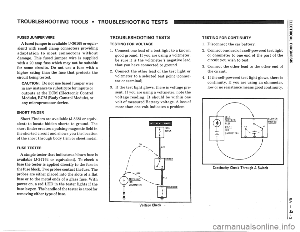
Voltage Check .
TESTING FOR CONTINUITY
1. Disconnect the car battery.
2. Connect one lead of a self-powered test light
or ohmmeter to one end of the part of the
circuit you wish to test.
3. Connect the other lead to the other end of
the circuit.
4. If the self-powered test light glows, there is
continuity. If you are using an ohmmeter,
low or no resistance means good continuity.
Continuity Check Through A Switch
Page 1185 of 1825
TROUBLESHOOTING TESTS
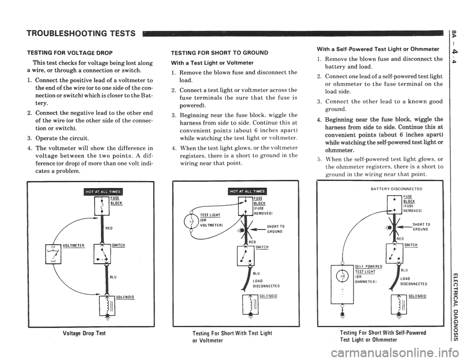
TESTING FOR VOLTAGE DROP
This test checks for voltage being lost along
a wire, or through a connection or switch.
1. Connect the positive lead of a voltmeter to
the end of the wire (or to one side of the con-
nection or switch) which
is closer to the Bat-
tery.
2. Connect the negative lead to the other end
of the wire (or the other side of the connec-
tion or switch).
3. Operate the circuit.
4. The voltmeter will show the difference in
voltage between the two points.
A dif-
ference (or drop) of more than one volt indi-
cates a problem.
Voltage Drop Test
TESTING FOR SHORT TO GROUND
With
a Test Light or Voltmeter
1. Remove the blown fuse and disconnect the
load.
2. Connect a test light or voltmeter across the
fuse terminals (be sure that the fuse is
powered).
3. Beginning near the fuse block, wiggle the
harness from side to side. Continue this at
convenient points (about
6 inches apart)
while watching the test light or voltmeter.
4. When the test light glows, or the \voltmeter
registers. there is a short to ground in the
wiring near that point.
Testing For Short With Test Light
or Voltmeter
With a Self-Powered Test Light or Ohmmeter
1. Remove the blown fuse and disconnect the
battery and load.
2. Connect one lead of a self-powered test light
or ohmmeter to the fuse terminal on the
load side.
3. Connect the other lead to a known good
ground.
4. Beginning near the fuse block, wiggle the
harness from side to side. Continue
this at
convenient points (about
6 inches apart)
while watching the self-powered test light or
ohmmeter.
,5. M'hen the self-powered test light glows, or
the ohmmeter registers. there is a short to
ground in the wiring near that point.
SELF POWERED
DISCONNECTED
Testing For Short With Self-Powered
Test Light or Ohmmeter
Page 1186 of 1825
TROUBLESHOOTING TESTS m r rn 0
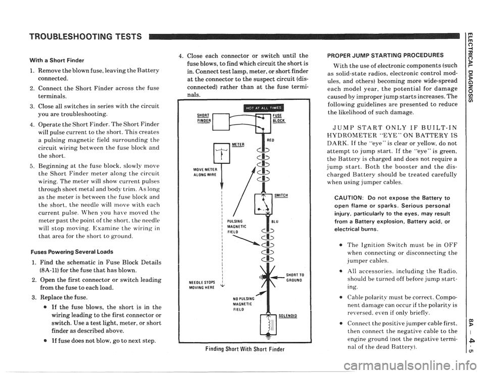
With a Short Finder
1. Remove the blown fuse, leaving the Battery
connected.
2. Connect the Short Finder across the fuse
terminals.
3. Close all switches in series with the circuit
you are troubleshooting.
4. Operate the Short Finder. The Short Finder
will pulse current to the short. This creates
a pulsing magnetic field surrounding the
circuit wiring between the fuse block and
the short.
5. Beginning at the fuse block. slowly move
the Short Finder meter along the circuit
wiring. The meter will show current pulses
through sheet
inetal and body trim. As long
as the meter is between the fuse block and
the short, the needle will move with each
current pulse. When you have
moved the
meter past the point of the short. the needle
will stop
moving. Examine the wiring in
that area for the short to ground.
Fuses Powering Several Loads
1. Find the schematic in Fuse Block Details
(8A-11) for the fuse that has blown.
2. Open the first connector or switch leading
from the fuse to each load.
3. Replace the fuse.
@ If the fuse blows, the short is in the
wiring leading to the first connector or
switch. Use a test light, meter, or short
finder as described above.
@ If fuse does not blow, go to next step.
4. Close each connector or switch until the PROPER JUMP STARTING PROCEDURES
fuse blows, to find which circuit the short is
With the use of electronic components (such
in. Connect test lamp, meter, or short finder
as solid-state radios, electronic control
mod- at the connector to the suspect circuit (dis- ules, and others) becoming more wide-spread
connected) rather than at the fuse termi- each model year, the potential for damage nals. caused by improper jump starts increases. The
SHORT FUSE FINDER - BLOCK -
MOVE METER
NEEDLE STOPS
MOVING HERE
NO PULSING
MAGNETIC
FIELD
Cb
SHORT TO
GROUND
w-
Finding Short With Short Finder
following guidelines are presented to reduce
the likelihood of such damage.
JUMP START ONLY IF BUILT-IN
HYDROMETER "EYE" ON BATTERY IS
DARK. If the "eye" is clear or yellow, do not
attempt to jump start. If the "eye" is green,
the Battery is charged and does not require a
jump start. Both the booster and the dis-
charged Battery should be treated carefully
when using jumper cables.
CAUTION: Do not expose the Battery to
open flame or sparks. Serious personal
injury, particularly
to the eyes, may result
from
a Battery explosion, Battery acid, or
electrical burns.
The Ignition Switch must be in OFF
when connecting or disconnecting the
jumper cables.
All accessories. including the Radio.
should be turned off before jump start-
ing.
Cable polarity must be correct. Compo-
nent damage can occur
if the polarity is
re~~ersed. even if only briefly.
a Connect the positive jumper cable first.
then connect the negative cable to the
engine ground (not the negative termi-
nal of the dead Battery).
Page 1187 of 1825
REPAIR PROCEDURES 0) B
ELECTRICAL REPAIRS
This section provides instruction in the fol-
lowing repairs:
- Circuit Protection
- Typical Electrical Repairs
- Splicing Copper Wire
- Splicing Aluminum \l.ire
- Splicing Txisted Shielded Cable
- Repairing Connectors (Except Weather
Pack
V and
- Repairing breather I'ack * (Environmen-
tal) Connectors
Note: After any electrical repair is made, always
test the circuit by operating the devices in the
circuit. This confirms not only that the repair is
correct, but also that the cause of the complaint
was correctly identified.
CIRCUIT PROTECTION
All electrical circuits are protected against
excessive loads which might occur because of
shorts or overloads in the wiring system. Such
protection is
prolrided by a fuse. circuit
breaker. or fusible link.
Fuses
The most common method of automotive
wiring circuit protection is the fuse. Whenever
there is an excessive amount of current flow-
ing through a circuit the fusible element will
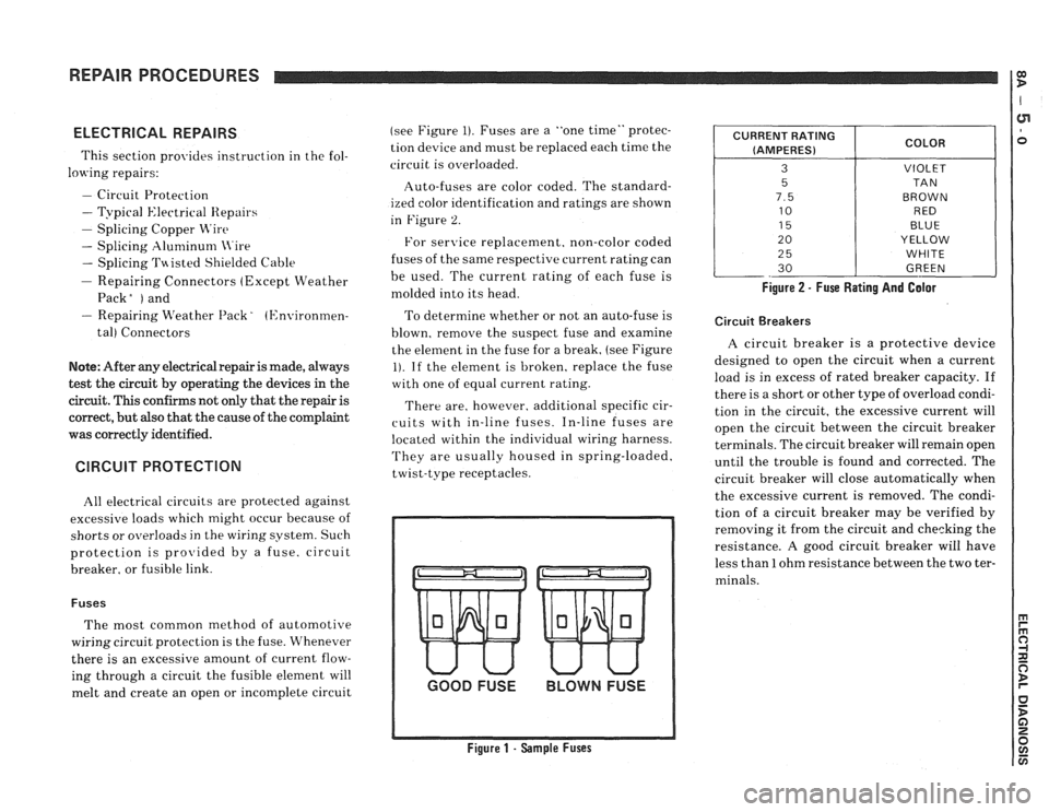
melt and create an open or incomplete circuit (see
Figure
1). Fuses are a "one time" protec-
tion device and must be replaced each time the
circuit is overloaded.
Auto-fuses are color coded. The standard-
ized color identification and ratings are shown
in Figure
2.
For senrice replacement. non-color coded
fuses of the same respective current rating can
be used. The current rating of each fuse is
molded into its head.
To determine whether or not an auto-fuse is
blown, remove the suspect fuse and examine
the element in the fuse for a break, (see Figure
1). If the element is broken, replace the fuse
with one of equal current rating.
There are, however. additional specific cir-
cuits with in-line fuses. In-line fuses are
located within the individual wiring harness.
They are usually housed in spring-loaded,
twist-type receptacles.
GOOD FUSE BLOWN FUSE
Figure 1 - Sample Fuses Figure
2 - Fuse Rating And Galor
CURRENT
RATING
(AMPERES)
3
5
7.5
10
15
20
2
5
30
Circuit Breakers
COLOR
VIOLET
TA N
BROWN RED
BLUE
YELLOW
WHITE
GREEN
A circuit breaker is a protective device
designed to open the circuit when a current
load is in excess of rated breaker capacity. If
there is a short or other type of overload condi-
tion in the circuit, the excessive current will
open the circuit between the circuit breaker
terminals. The circuit breaker will remain open
until the trouble is found and corrected. The
circuit breaker will close automatically when
the excessive current is removed. The condi-
tion of a circuit breaker may be verified by
removing it from the circuit and checking the
resistance.
A good circuit breaker will have
less than
1 ohm resistance between the two ter-
minals.
Page 1188 of 1825
REPAIR PROCEDURES
Fusible Links
In addition to circuit breakers and fuses,
some circuits use fusible links to protect the
wiring. Like fuses, fusible links are "one time
"
protection devices that will melt and create an
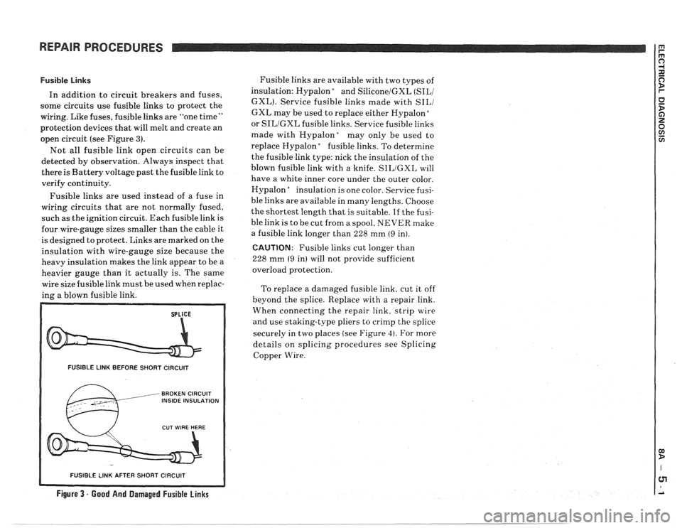
open circuit (see Figure
3).
Not all fusible link open circuits can be
detected by observation. Always inspect that
there is Battery voltage past the fusible link to
verify continuity.
Fusible links are used instead of a fuse in
wiring circuits that are not normally fused,
such as the ignition circuit. Each fusible link is
four wire-gauge sizes smaller than the cable it
is designed to protect. Links are marked on the
insulation with wire-gauge size because the
heavy insulation makes the link appear to be a
heavier gauge than it actually is. The same
wire size fusible link must be used when replac-
ing a blown fusible link.
FUSIBLE LINK BEFORE SHORT CIRCUIT
, BROKEN CIRCUIT INSIDE INSULATION
Fusible links are available with two types of
insulation: Hypalon
bnd SiliconelGXL (SILI
GXL). Service fusible links made with SILI
GXL may be used to replace either Hypalon "
or SILIGXL fusible links. Service fusible links
made with
Hypalonday only be used to
replace Hypalon
"fusible links. To determine
the fusible link type: nick the insulation of the
blown fusible link with a knife.
SILIGXL will
have a white inner core under the outer color.
Hypalon
"nsulation is one color. Service fusi-
ble links are available in many lengths. Choose
the shortest length that is suitable.
If the fusi-
ble link is to be cut from a spool, NEVER make
a fusible link longer than 228 mm
(9 in).
CAUTION: Fusible links cut longer than
228 mm
(9 in) will not provide sufficient
overload protection.
To replace a damaged fusible link, cut it off
beyond the splice. Replace with a repair link.
When connecting the repair link. strip wire
and use staking-type pliers to crimp the splice
securely in two places (see Figure
4). For more
details on splicing procedures see Splicing
Copper Wire.
R SHORT CIRCUIT
Figure 3 - Good And Damaged Fusible Links
-- - - - - -- - - - - -- - - -
Page 1189 of 1825
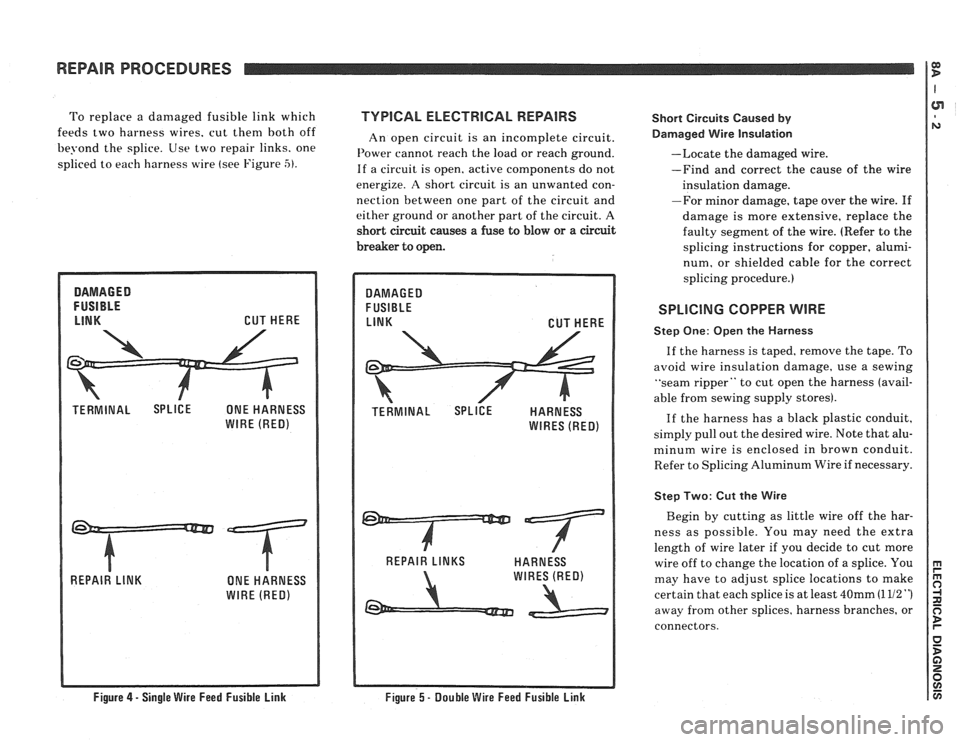
To replace a damaged fusible link which TVPlCAL ELECTRlCAL REPAIRS
feeds two harness wires. cut then1 both off
An open circuit is an incomplete circuit.
be?-ond the splice. Use two repair links. one I'ower cannot reach the load or reach ground.
spliced to each harness wire (see Figure -5). If a circuit is open. active components do not
energize.
A short circuit is an unwanted con-
nection between one part of the circuit and
either ground or another part of the circuit. A
short circuit causes
a fuse to blow or a circuit
breaker to open. Short
Circuits Caused
by
Darnaged Wire Insulation
--Locate the damaged wire.
-Find and correct the cause of the wire
insulation damage.
-For minor damage, tape over the wire.
If
damage is more extensive, replace the
faulty segment of the wire. (Refer to the
splicing instructions for copper, alumi-
num, or shielded cable for the correct
splicing procedure.)
REPAIR PROCEDURES
SPLICING COPPER WIRE
Q) D
Step One: Open the Harness
If the harness is taped, remove the tape. To
avoid wire insulation damage, use a sewing
"seam ripper" to cut open the harness (avail-
able from sewing supply stores).
If the harness has a black plastic conduit,
simply pull out the desired wire. Note that alu-
minum wire is enclosed in brown conduit.
Refer to Splicing Aluminum Wire if necessary.
Step Two: Cut the Wire
Begin by cutting as little wire off the har-
ness as possible. You may need the extra
length of wire later if you decide to cut more
wire off to change the location of a splice. You
may have to adjust splice locations to make
certain that each splice is at least
40mm (1 112 ")
away from other splices, harness branches, or
connectors.
Figure 4 - Single Wire Feed Fusible Link
Figure 5 - Double Wire Feed Fusible Link
Page 1190 of 1825
REPAIR PROCEDURES
Step Three: Strip the Insulation
When replacing a wire. use a wire of the same
size as the original wire or larger. The schemat-
ics list wire size in metric units. The following
table (see Figure
6) shows the commercial
(AWG) wire sizes that can be used to replace
each
metric wire size. Each AWG size is either
equal to or larger than the equivalent metric
size.
METRIC WIRE
SIZES
.22
.35
.5
.8
13.0
32.0
AWG
SIZES
Figure 6 - Wire Size Conversion Table
To find the correct wire size either find the
wire on the schematic page and convert the
metric size to the AR'G size. or use an
An'(;
wire gage.
If you aren't sure of the wire size. start with
the largest opening in your wire stripper and
work down until you get a clean strip of the
insulation. Be careful to avoid nicking or cut-
ting any of the wires.
Check the stripped wire for nicks or cut
strands. If the wire is damaged. repeat the pro-
cedure on a new section of wire. The two
stripped wire ends should be equal in length.
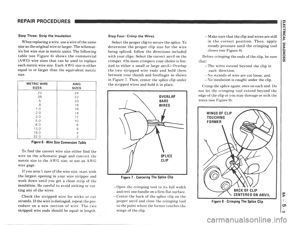
Step Four: Crirnp the Wires
Select the proper clip to secure the splice. '1'0
determine the proper clip size for the wire
heing spliced. follow the directions included
with your clips. Select the correct anvil on the
crimper. (On most crimpers your choice is
lim-
ited to either a small or large anvil.) Overlap
the two stripped wire ends and hold them
between your
thumb and forefinger as shown
in Figure
7. Then, center the splice clip under
the stripped wires and hold it in place.
-Open the crimping tool to its full width
and rest one handle on a firm flat surface.
--Center the back of the splice clip on the
proper
anvil and close the crinlping tool
to the point where the former touches the
wings of the clip. -Make
sure that the clip and wires are still
in the correct position. Then, apply
steady pressure until the crimping tool
closes (see Figure
8).
Before crimping the ends of the clip, be sure
that:
--The wires extend beyond the clip in
each direction.
-No strands of wire are cut loose, and
-No insulation is caught under the clip.
Crirnp the splice again. once on each end. Do
not let the crimping tool extend beyond the
edge of the clip or you may damage or nick the
wires (see Figure
9).
/ CENTERED ON ANVIL
Figure 8 - Crimping The Splice Clip