PONTIAC FIERO 1988 Service Repair Manual
Manufacturer: PONTIAC, Model Year: 1988, Model line: FIERO, Model: PONTIAC FIERO 1988Pages: 1825, PDF Size: 99.44 MB
Page 1201 of 1825
REPAIR PRQCEDURES
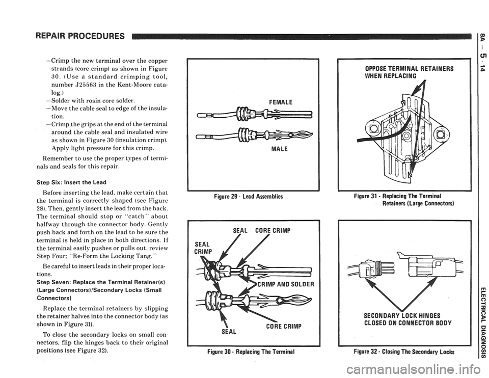
-Crimp the new terminal over the copper
strands (core crimp) as shown in Figure
30. (Use a standard crimping tool,
number
525563 in the Kent-Moore cata-
log.
I
-Solder with rosin core solder.
-Move the cable seal to edge of the insula-
tion.
-Crimp the grips at the end of the terminal
around the cable seal and insulated
wire
as shown in Figure 30 (insulation crimp).
Apply light pressure for this crimp.
Remember to use the proper types of termi-
nals and seals for this repair.
Step Six: Insert the Lead
Before inserting the lead. make certain that
the terminal is correctly shaped (see Figure
281. Then. gently insert the lead from the back.
The terminal should stop or "catch" about
halfway through the connector body. Gently
push back and forth on the lead to be sure the
terminal is held in place in both directions.
If
the terminal easily pushes or pulls out, review
Step Four; "Re-Form the Locking Tang.
"
Be careful to insert leads in their proper loca-
tions.
Step Seven: Replace the Terminal Retainer(s)
(Large Connectors)lSecondary Locks (Small
Connectors)
Replace the terminal retainers by slipping
the retainer halves into the connector body
!as
shown in Figure 31).
To close the secondary locks on small con-
nectors, flip the hinges back to their original
positions (see Figure
32).
I
FEMALE
MALE
Figure 29
- Lead Assemblies
SEAL CORE CRIMP
CRIMP AND SOLDER
CORE CRIMP
SEAL
Figure
30 - Replacing The Terminal OPPOSE
TERMINAL RETAINERS
WHEN REPLACING
Figure 31
- Replacing The Terminal
Retainers (Large Connectors)
SECONDARY LOCK
HINGES
CLOSED ON CONNECTOR BODY
Figure 32 - Closing The Secondary Locks
Page 1202 of 1825
REPAIR PROCEDURES m I L
REPAlRlNG METRI-PACK SERIES 150
CONNECTORS
(Pull-to-Seat Type)
Metri-Pack connectors are used to connect
various sensors such as the cam, crankshaft
and coolant sensors to primary harnesses in
the engine compartment. The Metri-Pack
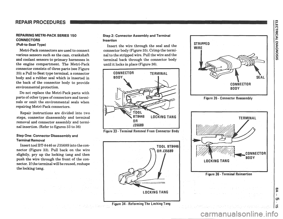
connector consists of three parts (see Figure
35): a Pull to Seat type terminal, a connector
body and
a rubber seal which is inserted in
the back of the connector body to provide
environmental protection.
Do
nc: replace the Metri-Pack parts with
parts of other types of connectors and termi-
nals or omit the environmental seals when
repairing Metri-Pack connectors.
Repair instructions are divided into
two
steps, connector disassembly and terminal
removal and connector assembly and termi-
nal insertion. (Refer to figures
33 to 36)
Step One: Connector Disassembly and
Terminal Removal
Insert tool BT-8446 or 535689 into the con-
nector (Figure
33). Pull back on the wire
slightly, pry up the locking tang and then
push the wire through the front of the con-
nector. If the terminal will be reused, reshape
the locking tang.
Step 2: Connector Assembly and Terminal
Insertion
Insert the wire through the seal and the
connector body (Figure
35). Crimp the termi-
nal to the stripped wire. Pull the wire and the
terminal back through the connector body
until it locks in place (Figure
36).
NECTOR TERMINAL
BT8446 LOCKING TANG
Figure 33
- Terminal Removal From Connector Body
TOOL
BT8446
Figure 35 - Connector Reassembly
Figure 36
- Terminal Reinsertion
Page 1203 of 1825
3 POWER DISTRIBUTION: V6 VlN S
Page 1204 of 1825
Page 1205 of 1825
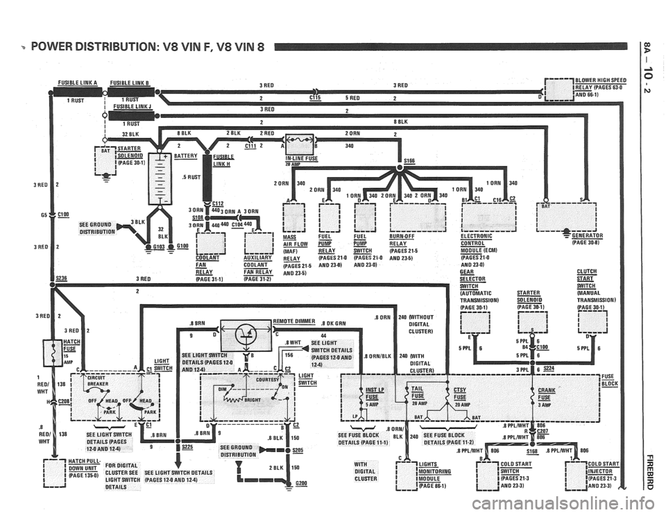
- POWER DISTRIBUTION: V8 VIN F, V8 VIN 8 I:
Page 1206 of 1825
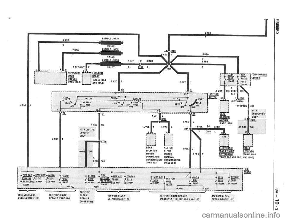
Page 1207 of 1825
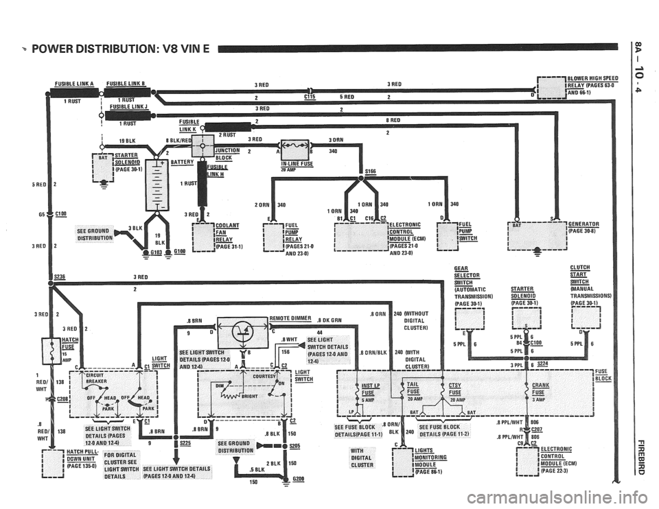
-. POWER DISTRIBUTION: V8 VIN E I
Page 1208 of 1825
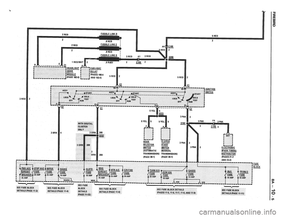
Page 1209 of 1825
POWER DISTRIBUTION
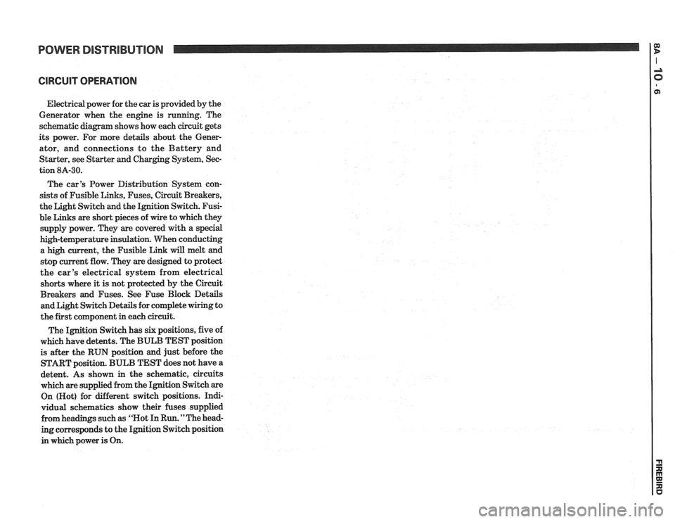
CIRCUIT OPERATION
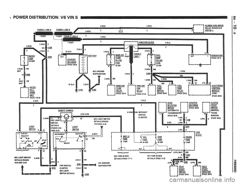
Electrical power for the car is provided by the
Generator when the engine is running. The
schematic diagram shows how each circuit gets
its power. For more details about the Gener-
ator, and connections to the Battery and
Starter, see Starter and Charging System, Sec-
tion
8A-30.
The car's Power Distribution System con-
sists of Fusible Links, Fuses, Circuit Breakers,
the Light Switch and the Ignition Switch. Fusi-
ble Links are short pieces of wire to which they
supply power. They are covered with a special
high-temperature insulation. When conducting
a high current, the Fusible Link will melt and
stop current flow. They are designed to protect
the car's electrical system from electrical
shorts where it is not protected by the Circuit
Breakers and Fuses. See Fuse Block Details
and Light Switch Details for complete wiring to
the first component in each circuit.
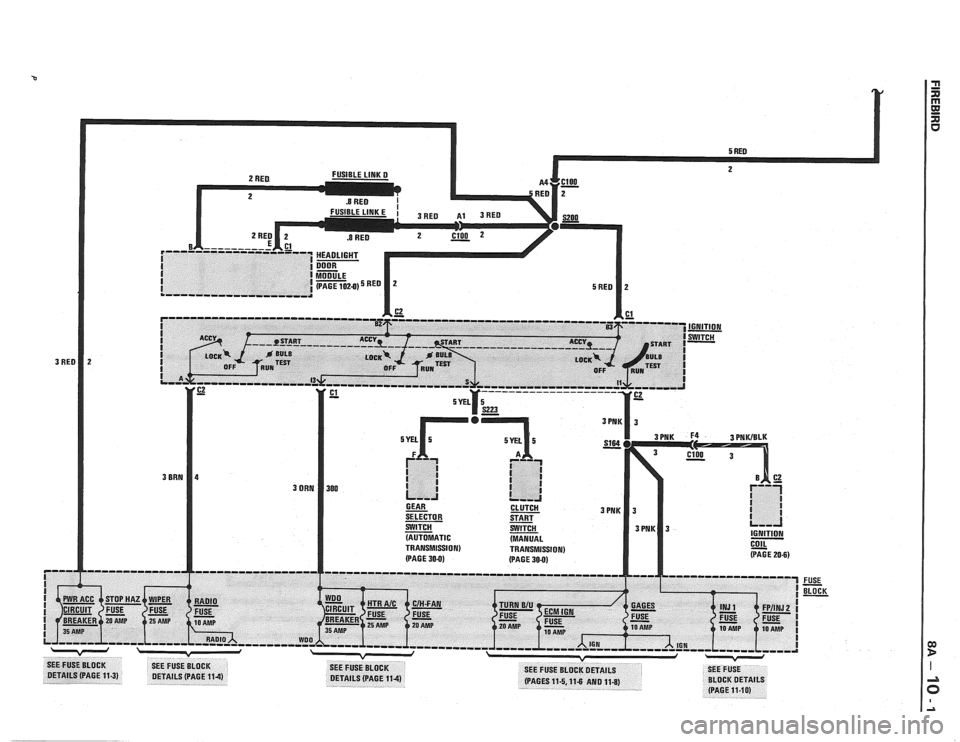
The Ignition Switch has six positions, five of
which have detents. The BULB TEST position
is after the RUN position and just before the
START position. BULB TEST does not have a
detent. As shown in the schematic, circuits
which are supplied from the Ignition Switch are
On (Hot) for different switch positions. Indi-
vidual schematics show their fuses supplied
from headings such as "Not In Run. "The head-
ing corresponds to the Ignition Switch position
in which power is On.
Page 1210 of 1825
BOWER DISTRIBUTION
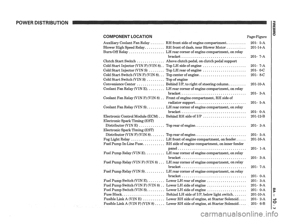
COMPONENT LOCATION Page-Figure
Auxiliary Coolant Fan Relay
. . . . . . . RH front side of engine compartment. . . . . . . . . .
Blower High Speed Relay. . . . . . . . . . RN front of dash, near Blower Motor . . . . . . . . . .
Burn-Off Relay . . . . . . . . . . . . . . . . . . LH rear corner of engine compartment, on relay
bracket
.................................
Clutch Start Switch . . . . . . . . . . . . . . Above clutch pedal, on clutch pedal support
Cold Start Injector (VIN F) (VIN
8). . Top LH side of engine . . . . . . . . . . . . . . . . . . . . . .
Cold Start Injector (VIN S) . . . . . . . . Top LH rear of engine . . . . . . . . . . . . . . . . . . . . . .
Cold Start Switch (VIN F) (VIN 8). . . Top center of engine. . . . . . . . . . . . . . . . . . . . . . . .
Cold Start Switch (VIN S) . . . . . . . . . Top of engine
Convenience Center
. . . . . . . . . . . . . . Behind IIP, to right of steering column. . . . . . . . .
Coolant Fan Relay (VIN E). . . . . . . . . LN rear corner of engine compartment, on relay
bracket
.................................
Coolant Fan Relay (VIN F) (VIN 8) . . Front of engine compartment, RH side of
radiator support.
. . . . . . . . . . . . . . . . . . . . . . . . .
Coolant Fan Relay (VIN S) . . . . . . . . . LH rear corner of engine compartment, on relay
bracket
.................................
Electronic Control Module (ECM) . . . Behind RN side of UP . . . . . . . . . . . . . . . . . . . . . .
Electronic Spark Timing (EST)
Distributor (VIN E)
. . . . . . . . . . . . . Top rear of engine. . . . . . . . . . . . . . . . . . . . . . . . . .
Electronic Spark Timing (EST)
Distributor (VIN F) (VIN
8). . . . . . . Top rear of engine. . . . . . . . . . . . . . . . . . . . . . . . . .
Fog Light Relay . . . . . . . . . . . . . . . . . LR front of engine compartment, on fender. . . . .
Fuel Pump In-Line Fuse. . . . . . . . . . . RR side of engine compartment, on inner fender
panel
...................................
Fuel Pump Relay (VIN E). . . . . . . . . . LN rear corner of engine compartment, on relay
bracket
.................................
Fuel Pump Relay (VIN F) (VIN 8) . . . LN rear corner of engine compartment, on relay
bracket
.................................
Fuel Pump Relay (VIN S) . . . . . . . . . . LH rear corner of engine compartment, on relay
bracket
.................................
Fuel Pump Switch (VIN E). . . . . . . . . Lower LN rear of engine . . . . . . . . . . . . . . . . . . . .
Fuel Pump Switch (VIN F) (VIN 8) . . Lower LN side of engine . . . . . . . . . . . . . . . . . . . .
Fuel Pump Switch (VIN S) . . . . . . . . . Lower LN side of engine . . . . . . . . . . . . . . . . . . . .
Fuse Block. . . . . . . . . . . . . . . . . . . . . . Behind LH side of IIP, below light switch. . . . . . .
Fusible Link A (VIN E) . . . . . . . . . . . Lower RN side of engine, at Starter Solenoid. . . .
Fusible Link A (VIN F) (VIN 8) . . . . . Lower RH side of engine, at Starter Solenoid. . . . 201- 6-B