tires PONTIAC FIERO 1988 Service Service Manual
[x] Cancel search | Manufacturer: PONTIAC, Model Year: 1988, Model line: FIERO, Model: PONTIAC FIERO 1988Pages: 1825, PDF Size: 99.44 MB
Page 325 of 1825
e Remove lug nuts securing rotor to hub.
e Lower car.
o Torque lug nuts. See WHEELS AND
TIRES.
SHOE AND LINING ASSEMBLIES
Figures 5 thru 8
Remove or Disconnect
1. Caliper as previously described.
2 Outboard shoe and lining (27) (Figure 5).
Install or Connect
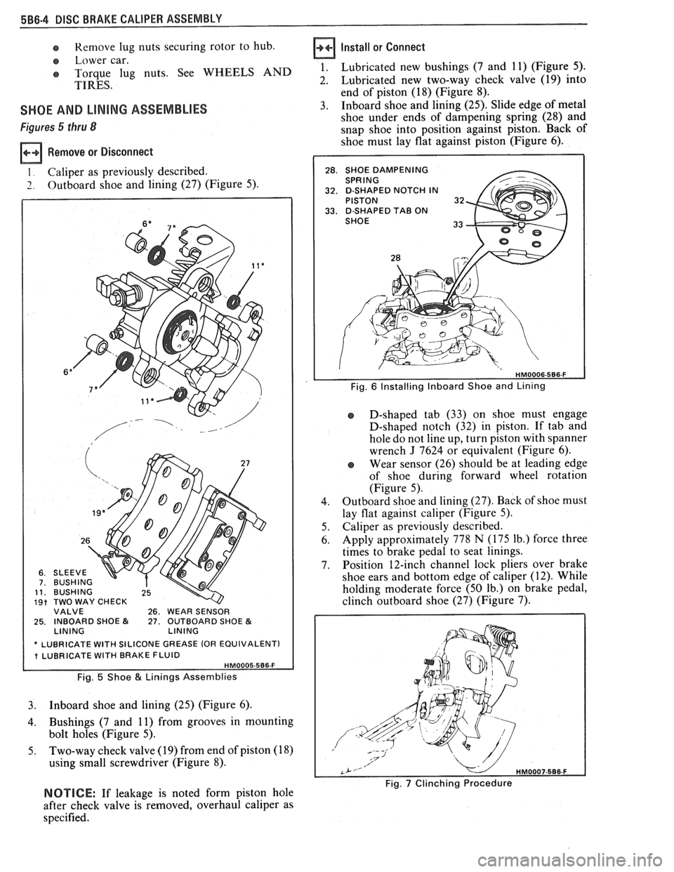
1. Lubricated new bushings (7 and 11) (Figure 5).
2. Lubricated new two-way check valve (19) into
end of piston (18) (Figure 8).
3. Inboard shoe and lining (25). Slide edge of metal
shoe under ends of dampening spring (28) and
snap shoe into position against piston. Back of
shoe must lay flat against piston (Figure 6).
Fig. 6 Installing Inboard Shoe and Lining
26. WEAR SENSOR 25. INBOARD SHOE & 27. OUTBOARD SHOE & LINING
ASE (OR EQUIVALENT)
Fig. 5 Shoe & Linings Assemblies
3. Inboard shoe and lining (25) (Figure 6).
4. Bushings (7 and 11) from grooves in mounting
bolt holes (Figure 5).
5. Two-way check valve (19) from end of piston (18)
using small screwdriver (Figure 8). D-shaped
tab (33) on shoe must engage
D-shaped notch (32) in piston. If tab and
hole do not line up, turn piston with spanner
wrench
J 7624 or equivalent (Figure 6).
r, Wear sensor (26) should be at leading edge
of shoe during forward wheel rotation
(Figure 5).
4. Outboard
shoe and lining (27). Back of shoe must
lay flat against caliper (Figure
5).
5. Caliper as previously described.
6. Apply approximately 778
N (175 lb.) force three
times to brake pedal to seat linings.
7. Position
12-inch channel lock pliers over brake
shoe ears and bottom edge of caliper (12). While
holding moderate force
(50 lb.) on brake pedal,
clinch outboard shoe (27) (Figure 7).
NOTICE: If leakage is noted form piston hole
after check valve is removed, overhaul caliper as
specified.
Page 331 of 1825
8. Actuator link (6) into actuator lever (7) while
holding up on lever.
9. Shoe return springs (1 and 2) using J 8057 pliers.
10. Brake drum.
1 1. Wheels and tires.
Lower car.
Torque wheel nuts. See Section 3E
WHEELS AND TIRES.
BRAKE ADJUSTMENT
See Figure 5
1. Raise car and suitably support.
Mark relationship of wheel to axle flange.
2. Wheel and tire.
o Mark relationship of drum to axle flange.
3. Measure drum inside diameter (ID) using J
21 177-A.
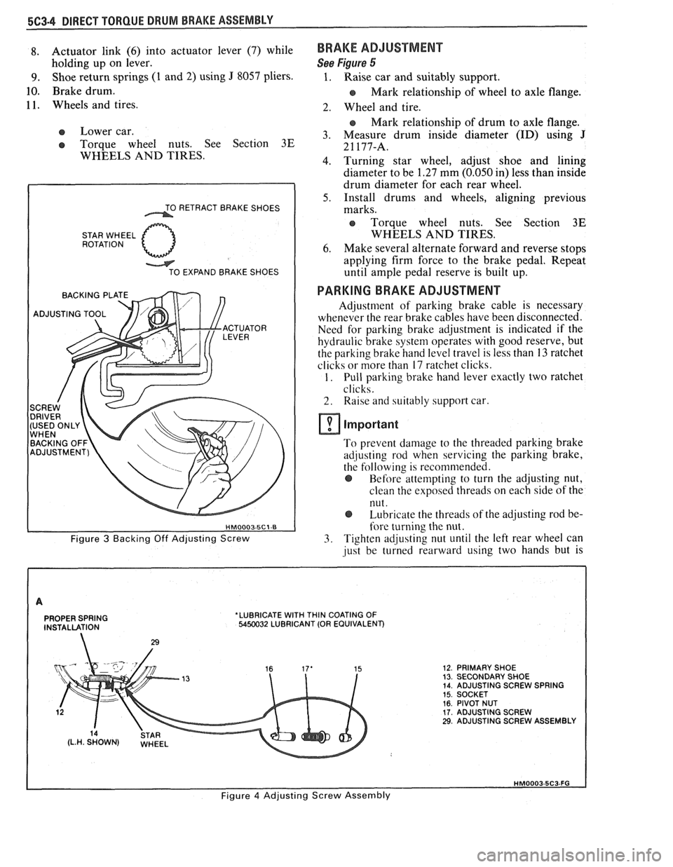
4. Turning star wheel, adjust shoe and lining
diameter to be 1.27 mm (0.050 in) less than inside
drum diameter for each rear wheel.
5. Install drums and wheels, aligning previous
marks.
s Torque wheel nuts. See Section 3E
WHEELS AND TIRES.
6. Make several alternate forward and reverse stops
applying firm force to the brake pedal. Repeat
until ample pedal reserve is built up.
TO RETRACT BRAKE SHOES
STAR WHEEL ROTATION
TO
EXPAND BRAKE SHOES
PARKING BRAKE ADJUSTMENT
Adjustment of parking brake cable is necessary
whenever the rear brake cables have been disconnected.
Need for parking brake adjustment is indicated if the
hydraulic brake system operates with good reserve, but
the parking brake hand level travel is less than 13 ratchet
clicks or more than 17 ratchet clicks.
1. Pull parking brake hand lever exactly two ratchet
clicks.
2. Raise and suitably support car.
important
To prevent damage to the threaded parking brake
adjusting rod when servicing the parking brake,
the following is recommended.
@ Before attempting to turn the adjusting nut,
clean the exposed threads on each side of the
nut.
@ Lubricate the threads of the adjusting rod be-
fore turning the nut.
Figure 3 Backing Off Adjusting Screw 3. Tighten adjusting nut until the left rear wheel can
just be turned rearward using two hands but is
PROPER SPRING 'LUBRICATE WITH THIN COATING OF 5450032 LUBRICANT (OR EQUIVALENT)
29
12. PRIMARY SHOE 13. SECONDARY SHOE 14. ADJUSTING SCREW SPRING 15. SOCKET 16. PIVOT NUT 17. ADJUSTING SCREW 29. ADJUSTING SCREW ASSEMBLY
Figure 4 Adjusting Screw Assembly
Page 417 of 1825
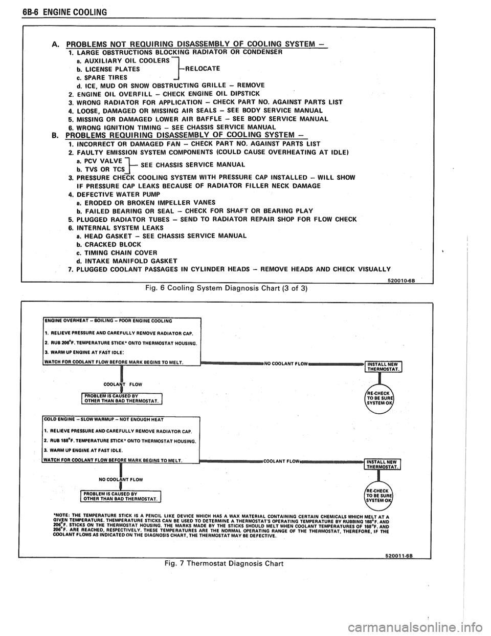
6B-8 ENGINE COOLING
PROBLEMS NOT REQUIRING DISASSEMBLY OF COOLING SYSTEM - 1. LARGE OBSTRUCTIONS BLOCKING RADIATOR OR CONDENSER
a. AUXILIARY OIL COOLERS
b. LICENSE PLATES R ELOCATE
c. SPARE TIRES
d. ICE, MUD OR SNOW OBSTRUCTING GRILLE - REMOVE
2. ENGINE OIL OVERFILL - CHECK ENGINE OIL DIPSTICK
3. WRONG RADIATOR FOR
APPLICATION - CHECK PART NO. AGAINST PARTS LlST
4. LOOSE, DAMAGED OR MISSING AIR SEALS - SEE BODY SERVICE MANUAL
5. MISSING OR DAMAGED LOWER AIR BAFFLE - SEE BODY SERVICE MANUAL
6. WRONG IGNITION TIMING - SEE CHASSIS SERVICE MANUAL PROBLEMS REQUIRING DISASSEMBLY OF COOLING SYSTEM -
1. INCORRECT OR DAMAGED FAN - CHECK PART NO. AGAINST PARTS LlST
2. FAULTY EMISSION SYSTEM COMPONENTS (COULD CAUSE OVERHEATING AT IDLE)
; SEE CHASSIS SERVICE MANUAL
3. PRESSURE CHECK COOLING SYSTEM WITH PRESSURE CAP INSTALLED - WILL SHOW
IF PRESSURE CAP LEAKS BECAUSE OF RADIATOR FILLER NECK DAMAGE
4. DEFECTIVE WATER PUMP
a. ERODED OR BROKEN IMPELLER VANES
b. FAILED BEARING OR SEAL - CHECK FOR SHAFT OR BEARING PLAY
5. PLUGGED RADIATOR TUBES - SEND TO RADIATOR REPAIR SHOP FOR FLOW CHECK
6. INTERNAL SYSTEM LEAKS
B. HEAD GASKET - SEE CHASSIS SERVICE MANUAL
b. CRACKED BLOCK
c. TIMING CHAIN COVER
d. INTAKE MANIFOLD GASKET
7. PLUGGED COOLANT PASSAGES IN CYLINDER HEADS - REMOVE HEADS AND CHECK VISUALLY
Fig. 6 Cooling System Diagnosis Chart (3 of 3)
1. RELIEVE PRESSURE AND CAREFULLY REMOVE RADIATOR CAP.
2. RUB W'F. TEMPERATURE STICK* ONTO THERMOSTAT MOUSING.
3. WARM UP ENGINE AT FAST IDLE:
WATCH FOR COOLANT FLOW BEFORE MAR
NO COOLANT FLOW INSTALL NEW
THERMOSTAT.
COLD ENGINE -SLOW WARMUP -NOT ENOUGH HEAT
1. RELIEVE PRESSURE AND CAREFULLY REMOVE RADIATOR CAP.
2. RUB 188'~. TEMPERATURE STICK' ONTO THERMOSTAT HOUSING.
3. WARM UP ENGINE AT FAST IDLE.
COOLANT FLOW
- 'NOTE: THE TEMPERATURE STICK IS A PENCIL LIKE DEVICE WHICH HAS A WAX MATERIAL CONTAINING CERTAIN CHEMICALS WHICH MELT AT A GIVEN TEMPERATURE THEWERATURE STICKS CAN BE USED TO DETERMINE A THERMOSTAT'S OPERATING TEMPERATURE BY RUBBING laB°F AN0 =OF. STICKS ON THE THERMOSTAT HOUSING. THE MARKS MADE BY THE STICKS SHOULD MELT WHEN COOLANT TEMPERATURES OF IWOF'AND W'F. ARE REACHED, RESPECTIVELY. THESE TEMPERATURES ARE THE NORMAL WERATING RANGE OF THE THERMOSTAT. THEREFORE, ~i WE COOLANT FLOWS AS INDICATED ON THE DIAGNOSIS CHART. THE THERMOSTAT MAY BE DEFECTIVE.
Fig. 7 Thermostat Diagnosis Chart
Page 552 of 1825
DRIVEABILITY AND EMISSIONS 5.OL (VIN E) 6E2-B-5
@ If the previous checks did not find the problem:
- Visually inspect ignition system for moisture,
dust, cracks, burns, etc. Spray plug wires with
fine water mist to check for shorts.
- Fuel System - Plugged fuel filter, water, low
pressure. See CHART A-7.
- Perform compression check.
- Valve timing.
- Remove rocker covers. Check for bent pushrods,
worn rocker arms, broken or weak valve springs,
worn camshaft lobes. Repair as necessary. See
Section
"6A".
If there is spray from only one injector, then,
there is
a malfunction in the injector assembly,
or in the signal to the injector assembly. The
malfunction can be isolated by switching the
injector connectors. If the problem remains with
the original injector, after switching the
connector, then the injector is defective. Replace
the iniector. If the
~roblem moves with the
injector connector, then, the problem is an
improper signal in the injector circuits. See
CHART A-3.
POOR FUEL ECONOMY
Definition: Fuel economy, as measured by an actual road test, is
noticeably lower than expected. Also, economy is noticeably lower than it
was on this car at one time, as previously shown by an actual road test.
@ CHECK: @ Visually (physically) check:
- Engine thermostat for faulty part (always open) - Vacuum hoses for splits, kinks, and proper
or for wrong heat range. See Section
"6B". connections, as shown on Vehicle Emission
- Fuel Pressure. See CHART A-7. Control Information label.
@ Check owner's driving habits. - Ignition wires for cracking, hardness, and proper
- Is A/C "ON" full time (Defroster mode "ON")? connections.
- Are tires at correct pressure? e Check ignition timing. See Emission Control
- Are excessively heavy loads being carried? Information label.
- Is acceleration too much, too often? @ Remove spark plugs. Check for cracks, wear,
- Suggest driver read "Important Facts on Fuel
improper gap, burned electrodes or heavy deposits.
Economy" in owner's manual. Repair
or replace, as necessary.
@ Perform "Diagnostic Circuit Check". @ Check compression. See Section "6A".
@ Check air cleaner element (filter) for dirt or @ Check TCC for proper operation. See CHART C-8.
being plugged. Use "Scan"
tool if available.
@ Check for proper calibration of speedometer. @ Check for dragging brakes.
Suggest owner fill fuel tank and recheck fuel
economy.
@ Check for exhaust system restriction. ,
See CHART B-1.
ROUGH, UNSTABLE, OR INCORRECT IDLE, STALLING
Definition: The engine runs unevenly at idle. If bad enough, the car may
shake. Also,
the idle may vary in rpm (called "hunting"). Either condition
may be severe enough to cause stalling. Engine idles at incorrect speed.
@ CHECK: - Vacuum leaks can cause higher than normal
- Ignition timing. See Emission Control idle.
Information label.
- EGR "ONJ', while idling, will cause roughness,
- PIN switch circuit. See CHART C-1 A. stalling, and hard starting. CHART C-7.
- For injectorb) leaking. Check fuel pressure, - Battery cables and ground straps should be clean ,
CHART A-7. and secure. Erratic voltage will cause IAC to
- IAC - See CHART C-2C.
change its position, resulting in poor idle quality.
- If a sticking throttle shaft or binding linkage - IAC valve will not move, if system voltage is
causes
a high TPS voltage (open throttle
below 9, or greater than 17.8 volts.
indication), the ECM will not control idle.
- Use "Scan" tool to determine if ECM is receiving
Monitor TPS voltage. "Scan"
andlor voltmeter AlC request signal.
should read less than
1.2 volts with throttle
closed.
Page 1118 of 1825
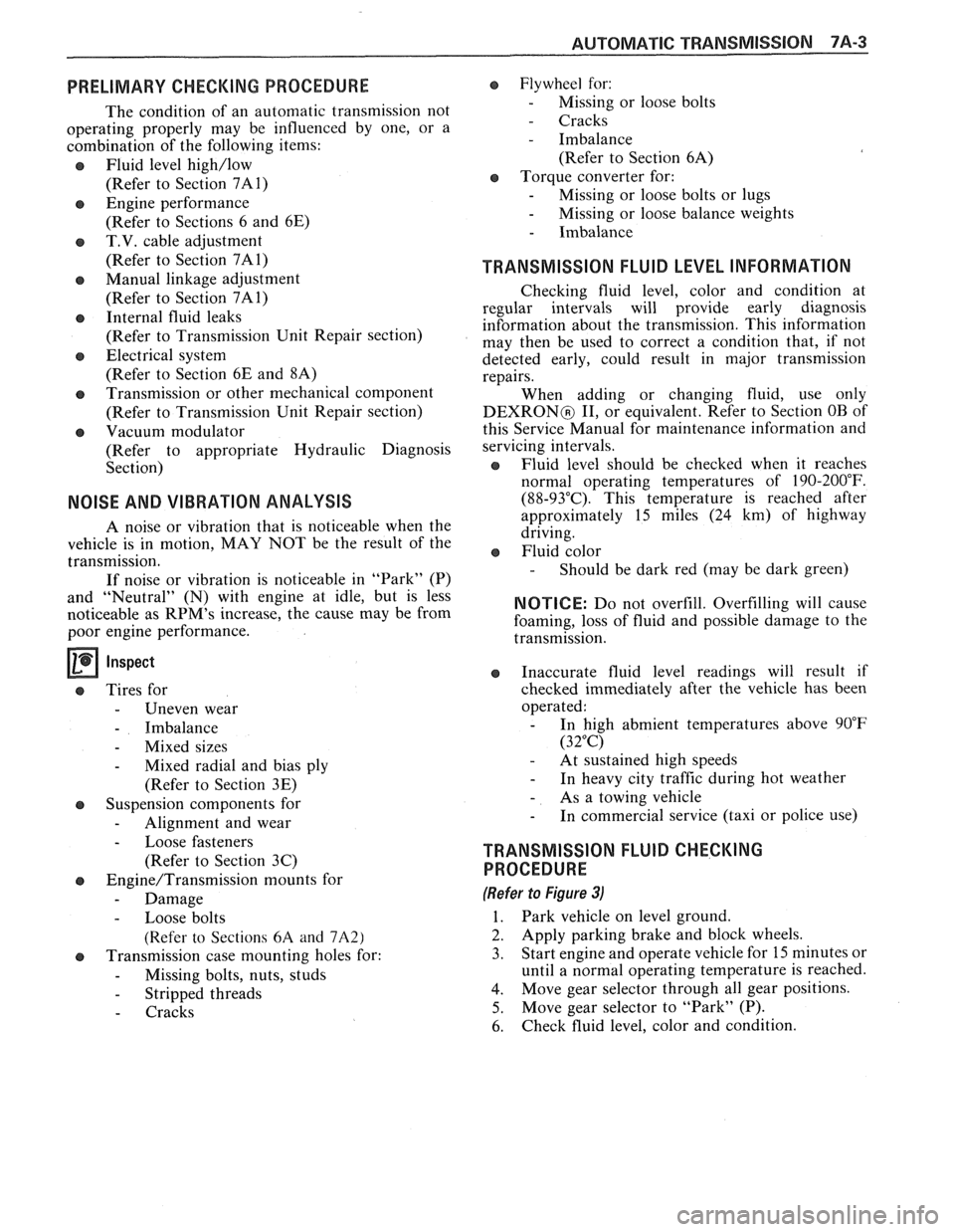
AUTOMATIC TRANSMISSION 7A-3
PRELIMARY CHECKING PROCEDURE
The condition of an automatic transmission not
operating properly may be influenced by one, or a
combination of the following items:
e Fluid level high/low
(Refer to Section 7A1)
e Engine performance
(Refer to Sections 6 and 6E)
T.V. cable adjustment
(Refer to Section
7A1)
e Manual linkage adjustment
(Refer to Section
7A1)
e Internal fluid leaks
(Refer to Transmission Unit Repair section)
e Electrical system
(Refer to Section 6E and 8A)
e Transmission or other mechanical component
(Refer to Transmission Unit Repair section)
e Vacuum modulator
(Refer to appropriate Hydraulic Diagnosis
Section)
NOISE AND VIBRATION ANALYSIS
A noise or vibration that is noticeable when the
vehicle is in motion, MAY NOT be the result of the
transmission.
If noise or vibration is noticeable in "Park"
(P)
and "Neutral" (N) with engine at idle, but is less
noticeable as
RPM's increase, the cause may be from
poor engine performance.
e Tires for
- Uneven wear
- Imbalance
- Mixed sizes
- Mixed radial and bias ply
(Refer to Section 3E)
e Suspension components for
- Alignment and wear
- Loose fasteners
(Refer to Section 3C)
e Engine/Transmission mounts for
- Damage
- Loose bolts
(Refer
to Sections 6A and 7A2)
e Transmission case mounting holes for:
- Missing bolts, nuts, studs
- Stripped threads
- Cracks
e Flywheel for:
- Missing or loose bolts
- Cracks
- Imbalance
(Refer to Section 6A)
e Torque converter for: - Missing or loose bolts or lugs - Missing or loose balance weights
- Imbalance
TRANSMISSION FLUID LEVEL INFORMATION
Checking fluid level, color and condition at
regular intervals will provide early diagnosis
information about the transmission. This information
may then be used to correct a condition that, if not
detected early, could result in major transmission
repairs.
When adding or changing fluid, use only
DEXRONO 11, or equivalent. Refer to Section OB of
this Service Manual for maintenance information and
servicing intervals.
Fluid level should be checked when it reaches
normal operating temperatures of
190-200°F.
(88-93°C). This temperature is reached after
approximately 15 miles (24 km) of highway
driving.
e Fluid color - Should be dark red (may be dark green)
NOTICE: Do not overfill. Overfilling will cause
foaming, loss of fluid and possible damage to the
transmission.
Inaccurate fluid level readings will result if
checked immediately after the vehicle has been
operated:
- In high abmient temperatures above 90°F
(32°C)
- At sustained high speeds
- In heavy city traffic during hot weather
- As a towing vehicle - In commercial service (taxi or police use)
TRANSMISSION FLUID CHECKING
PROCEDURE
(Refer to Figure 3)
1. Park vehicle on level ground.
2. Apply parking
brake and block wheels.
3. Start
engine and operate vehicle for 15 minutes or
until a normal operating temperature is reached.
4. Move gear
selector through all gear positions.
5. Move
gear selector to "Park" (P).
6. Check fluid level, color and condition.
Page 1818 of 1825
Battery .......................................................... 6D1-2
Brakes
.................................................................. 5-3
................................ Bumper. Energy Absorber 2B-2
........................................... Charging System 6D3- 1
........................................ Cooling and Radiator 6B-3
....................... ................ Cranking System .. 6D2- 1
Cruise Control
................................. 9B-4, 8A-34-0
......................................... Drive Axles (Rear) 4B1-2
Engine Performance
......................................... 6-3
.............................................. Ignition System 6D4-3
Instrument Panel, Gages and
.................................................... Console 8C-3
............................. Miscellaneous Accessories 9G-2
............................................... Power Antenna 9A-2
Power Recirculation Ball
.................................. 3-3
Power Steering Pumps
........................................ 3-4
.............................................. Propeller Shaft 4A- 1
................................................................ Radio 9A-1
.............. Seal Replacement Recommendations 3- 10
........................ . Steering Gear and Pump Leaks 3-10
.............. Strut Dampener and Shock Absorber 3- 12
.................................................... Trim
Height 3- 14
.................................................. Steering Linkage 3-3
Steering, Suspension, Tires and
Wheels
.............................. .. ................. Section 3
Steering Wheels and Columns
............................ 3-4 ......................................................... Vibrations 3- 14
................................................. Wheel Bearing 3-14 .............................................. Wheels and Tires 3- 13
........................... Windshield Wiper System 8El-2
............................................. Digital Cloclc 8A- 150-0
Disc Brake Caliper Assembly
.......................................... (3000/3 100 Series) 5B1
............... ................... General Description .. 5B 1-2 ............................................... On-Car Service 5B 1-2
...................................... Caliper Assembly 5B 1-2
.......................... Shoe and Lining Assembly 5B 1-4
...................................................... Unit Repair
5B 1-4
.......................................... Caliper Overhaul 5B 1-4
?isc Brake Caliper Assembly (3548
Series)
............................................................. 5B6
General Description
....................................... 5B6-2
On-Car Service
............................................... 5B6-2
....................................... Caliper Assembly 5B6-2
.......................... Parking Brake Adjustment 5B6-3
.......................... Shoe and Lining Assembly 5B6-4
Unit Repair
............................... ... .................... 5B6-5
Caliper Overhaul
.......................................... 5B6-5
.......................... Door Lock Relay (Circuit) 8A- 130-0
Driveability and Emissions
........................ Section 6E
Fuel Injection (Port)
..................................... 6E3-1
Index
................................... follows 6E3-(213-2
...................................... Fuel Injection (TB 1) .6E
2- 1
...................................... Index follows 6E2-C 14-4
Drum Brake Assembly
................... ......... Section 5C3
General Description
......................... ... ............ 5C3-1
........................................... On-Car Service 5C3- 1
Backing Plate
........................................ 5C3-7
....................................... Brake Adjustment .5C 3-4
..................................... Brake Components 5C3-1
Parking Brake Adjustment
.......................... 5C3-4
Wheel Cylinder ........................................... 5C3-5 ..................................................... Unit Repair 5C3-7
............................ Wheel Cylinder Overhaul 5C3-7
CHASSIS INDEX m3
E
........................ Electric Rear Window Defogger 9G-2 ............................................ Electrical Diagnosis 88-1
Audible Alarms .............................................. 81%-77
.......................................... Component Data 818-201
.................................................... Headlights 8A- 100
........................ Heating and Air Conditioning 8A-60 .............................................................. Index $A- 1
........................................... Instrument Panel .8 A-82
.................................................. Introduction 8A-2
........................................................... Lights .8 A- 100
............................................ Repair Procedure 88-5 ........................................ Seats and Mirrors 8A- 141
......................................................... Symbols 8A-3
Troubleshooting Procedures ............................ 8A-4
.................................................. ... Windows .. .8 A- 120
............................................... Wiper/Washers .8 A-90
Electronic Glare Control Mirror
........................ 9G-4
.......................... Electronic Instrument Cluster 86-4, 6
Emissions and Driveability
....................................... Fuel Injection (Port) 6E3- 1
....................................... Fuel Injection (TB1) 6E2-1
Engine
.... V-6 2.8L VIN CODE S RPO (LB8) Section 6A2
.... V-8 5.OL VIN E and F, 5.7L VIN 8 Section 6A3
................................................. Cooling Section 6B
Engine Specifications
............................................................ V-6 6A2-26
............................................................. V-8 683-28
General Description
.............................................................. V-6 61 ............................................................. V-8 6A3-1
Lubrication System ........................................................... V-6 ..6A 2- 1
................................................................ V-8 6A3-2
Multi-port Fuel Injection
..................................................... VIN S 8A-20-0
................................................. VIN 8 8A-23-0
............ Throttle Body Injection (VIN E) 8A-22-0
................ Tuned Port Injection (VIN F) 8A-2 1-0
On-Vehicle Service Camshaft
......................................................... V-6 6A2-16
................................ ..................... V-8 .. 6A3-16
Camshaft Bearings
......................................................... V-6 6A2-16
...................................................... V-8 ..6A 3-17
Connecting Rod Bearings
......................................................... V-6 .6A 2- 18
................................................... V-8 6A3-13
...................... Crankcase (Front Cover) .6A
2- 15
............ Crankcase/Camshaft Sensors Section 6E3
Crankshaft
....................................................... V-6 6A2-25
......................................................... V-8 .6A 3-28
......................................... Cylinder Block .6A 3-26
Cylinder Head
.......................................................... V-6 682-12
.......................................................... V-8 6A3-11
Dipstick Tube .............................................. 6A3-7
Engine Assembly
....................................................... V-6 6212
.......................................................... V-8 6A3-27
Exhaust Manifold
........................................................ V-6 .6A 2-9
V-8
....................................................... 6A3-7
Page 1823 of 1825
8- CHASSIS INDEX
Recommended Fluids and Lubricants ................ OB-6
Relay Rod
......................................................... 3B6-2
Remote Mirror Control
...... See Body Service Section
5H.1. 15
Repair Procedures
.......................................... 88-50
S
........................................ Scheduled Maintenance OB- 1
Seats (Power) ....................................... Lumbar Support 8A- 145-0
............................. Sequential Fuel Injection 6E3-C2- 1
Service Engine Soon Light
.................................... 8C-3
Sheet Metal and Grille
................................ Section 2C
......................................... General Description .2 C. 1
........................................... Service Procedures .2 C. 1
................................................................. Hood .2 C. 1
...................................................... Hood Hinge 2C-2
Hood Latch and Cable
...................................... 2C-2
Paint
.............................................. Color Matching 2C-5
................................................ Identification -32-6
Interior Plastic Parts ...................................... 2C-6
................................................ Shock Absorbers 3D-
1
Shoe and Lining Assembly
. Brake
............................................ 3000/3 100 Series 5B1-3
3548 Series ...................................................... 5B6-4
Side Marker Lights
.............................................. 8B-2
........ Speakers See 8A- 150-0 & Body
Manual Section
6H- 1
.................... Spark Plug Gap .. .................. 6E3-13-3
................................ Speaker and Speaker Grille 9A-9
Special Tools
............................................ Air Conditioning 1 B-3 5
Air Conditioning Compressor
................................................. Overhaul 1D1-21
........................ Automatic Transaxle AT-700-R4-64
................................................................ Brakes SF-1
Clutch ................................................................ 7C-8
................................................................ Rear 4B1-20
....................................... Rear (Borg Warner) 4B-20
........................... Driveability and Emissions .6 E. 17
................................................ Engine Cooling 6B- 14
Power Steering Pump
& Gear ...................... 3B7-17
............................................... Propeller Shaft .4 A. 12
Steering Wheels and Columns
.......................... 5-35
Specifications Automatic Transmission Unit
............................................ Repair AT-700-R4-59
..................................................... Battery 6D 1-7
................................................................ Brakes 5F-1
Bumpers
......................................................... 2B-5
Charging System
................ .. ................... 6D3-3
.............................................................. Clutch .7 (2.8
....................................... Cranking System 6D2- 1 1
Driveability and Emissions ............................ 6E-23
................................................ Engine (V-6) ..6A 2.26
Engine (V-8) .................................................. 683-28
........................................ Front Suspension 3C- 10
Power Steering Gear and Pump
.................. 3B7-18 ............................................. Propeller Shaft .4 A. 12 ........................................................ Rear Axle 4B-19 ............................ Rear Axle (Borg Warner) 4B 1- 19
Rear Suspension
.............................................. 3D-9
.......................................... Replacement Bulbs 8Br 10 .............................................. Steering Linkage 3B6-6
Steering Wheels and Columns
...................... 3B5-35
........................................ Wheel Alignments 3A-4
....................................................... Speedometer 8C-2
........................................ Speedometer (Removal) 8C-5
...................................................... Speed Sensors 8C-1
Starter ........................................ Section 6D2. 8A-30-0
............................................. Starter (Circuit) 8A-30-0
Steering Linkage ...................................... Section 3B6
....................................... General Description 3B6-1
........................ Maintenance and Adjustments 3B6-1
................................................ On-Car Service 3B6-2
..................................................... Idler Arm 3B6-4
................................................ Pitman Arm 3B6-5
.................................................... Relay Rod 3B6-3
Tie Rods
...................................................... 3B6-2
.................................................. Specifications 3B6-6
Steering, Suspension, Tires and
Wheels Diagnosis
............................................................. 3-1
Steering Wheels and Columns
............................ 3B5-1
..................................... General Information 3B5- 1
Maintenance and Adjustments
...................... 3B5-'
On-Car Service .............................. .. ........... 3B5
Checking for Accident Damage
.................. 3B5-5
Intermediate Shaft ............... .. .................... 3B5-3
Park Lock Cable .......................................... 3B5-4
Standard Column
............................. Automatic Transaxle 3B5-13
Manual Transaxle ................................. 3B5- 19
Tilt Column
.............................. Automatic Transaxle 3B5-27
.................................. Manual Transaxle 3B5-19
Unit Repair Intermediate Shaft
...................................................... Assembly 3B5-6
................................................. Special Tools 3B5-35
Torque Specifications
.................................... 3B5-35
............................................. Starting System 8A-30-0
........................................ Strut Assembly (Front) 3C-4
.................................... ..... Symbols Chart ... 8A-3-0
T
.......................................................... Tachometer 9G-1
Tail/Stop/Turn Signal/Lights .......................... 8B-2
Temperature Cable
.............................................. 112 A-
Temperature Warning Light ................................ 8C-3
Theft Deterrent (Circuit)
.............................. 8A-133-0
Tie Rods
.............................................................. 3B6-2
Tires and Wheels
........................................ Section 3E
Diagnosis
.................................................. Section 3
General Information
......................................... 3E-1
................................................... Metric Tires 3E-2
....................................... Replacement Tires .31 E-
.................................................... Tire Placard 3E-2
........................................................... Wheels 3E-2
Maintenance and Adjustments
.......................... 3E-2
.......................... Aluminum Wheel Cleaning 3E-9
............................. ......... Inflation of Tires .. 3E-3
........................................ Tire Chain Usage 3E-4
.................................................. Tire Rotation 3E-3
.............................................. Wheel Repair 3E-2
...................................... Wheel Studs/Nuts 3E-3
........................................... Service Operations 3E-4
........................ Aluminum Wheel Cleaning 3E-9
.................................... Balance Precautions 3E-7
............................ Balancing Tire and Wheel 3E-7
.............................................. Compact Spare 3E-6
........................ Correcting Nonuniform Tires 3E-8