PONTIAC FIERO 1988 Service Repair Manual
Manufacturer: PONTIAC, Model Year: 1988, Model line: FIERO, Model: PONTIAC FIERO 1988Pages: 1825, PDF Size: 99.44 MB
Page 941 of 1825

6E3-C7-6 5.OL (VIN F) & 5.7L (WIN 8) DRIVEABILITY AND EMISSIONS
BLANK
Page 942 of 1825
DWlVEABlLlTV AND EMISSIONS 5.01, QVIN F) & 5.71 (VIN 8) 6E3-C8-1
TRANSMISSION CONVERTER CLUTCH (KC) SYSTEM
AND MANUAL "TRANSMISSION SHlFT LBGH"O"=Ob ONLY
CONTENTS
................ GENERAL DESCRIPTION C8-1 DIAGNOSIS ....................... .. C8-1
........ PURPOSE ......................... CS-1 SHIFT LIGHT (MIT) DESCRIPTION C8-1
....................... OPERATION C8-1 DIAGNOSIS ......................... CS-1
OM-CAR SERVICE ..................... C8-1
GENERAL DESCRIPTION
PURPOSE
The transmission converter clutch (TCC) system
uses
a solenoid operated valve in the automatic
transmission to couple the engine flywheel to the
output shaft of the transmission thru the torque
converter. This reduces the slippage losses in the
converter, which increases fuel economy.
OPERATION
For the converter clutch to apply, two conditions
must be met:
e Internal transmission fluid pressure must be
correct. For information on internal transmission
operation, see Section
"7A". This section will
cover only the electrical operation of the TCC
system.
@ The ECM grounds a switch internally to turn
"ON" a solenoid in the transmission. This moves a
check ball, which will allow the converter clutch
to apply, if the hydraulic pressure is correct, as
described above.
The ECM controls the TCC apply solenoid by
looking at several sensors:
@ Speedo Buffer Sensor (also called Vehicle Speed
Sensor
(VSS) Speed must be above a certain value
before the clutch can apply.
@ Coolant Temperature Sensor Engine must be
warmed
LIP before clutch can apply about 65" C
(149°F).
Throttle Position Sensor (TPS) After the
converter clutch applies, the ECM uses the
information
from the TPS to release the clutch
when the car is accelerating or decelerating at
a
certain rate.
The brake switch
is also part of the 'I'CC circuit as
it will remove battery voltage to the
'FCC solenoid
when the brake pedal is depressed.
@ Gear Select Switch The 4th gear switch is used to
send a signal to the ECM telling it when the
transmission is in 4th
gear
The ECM uses this information to vary the conditions
under which the clutch applies or releases. However,
the transmission does not have to be in fourth gear in
order for the ECM to turn the clutch "ON".
If the converter clutch is applied at all times, the
engine will stall immediately, just as in a manual
transmission with the clutch applied.
If the converter
clutch does not apply, fuel
ecomony may be lower than expected. If the vehicle
speed sensor fails, the TCC will not apply. If the 4th
gear switch does not operate, the TCC may not apply
at the right time.
DIAGNOSIS
The diagnosis of the TCC system is covered in
CHART C-$A. If the ECM detects a problem in the
system, a Code 24 should set. In this case, see Code 24
CHART.
SHIFT LIGHT (MR) DESCRIPTION
The purpose of the shift light is to provide a
display which indicates the optimum fuel economy
point for up shifting the manual transmission based
on engine speed and load. The display is
a lamp on the
instrument panel. Activation
of the ECM driver turns
the lamp "ON".
DIAGNOSIS
The shift light circuit can be checked using
CEIAR'I' C-8B.
ON-CAR SERVICE
See Section "8B" if the shift light bulb needs
replacement.
See Section
"GE" to repair wiring problem.
@ See Section "C- 1" if ECM is to be replaced.
Page 943 of 1825
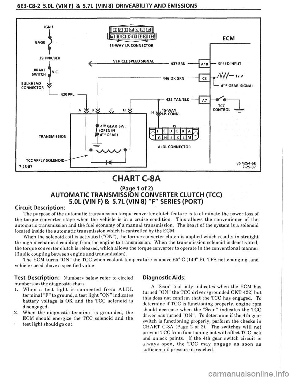
6E3-C8-2 5.OL (VIN F) & 5.7L (VIN 8) DRIVEABILITY AND EMISSIONS
15-WAY I.P. CONNECTOR
VEHICLE SPEED SIGNAL
SPEED INPUT
4TH GEAR SIGNAL
422
TANIBLK
4TH GEAR SW.
TRANSMISSION ALDL CONNECTOR
TCC APPLY SOLENOID
CHART C-8A
(Page 1 of 2)
AUTOMATIC TRANSMISSION CONVERTER CLUTCH (TCC)
5.OL (VIN F) & 5.7L (VIN 8) "F'" SERIES (PORT)
Circuit Description:
The purpose of the automatic transmission torque converter clutch feature is to eliminate the power loss of
the torque converter stage when the vehicle is in a cruise condition. This allows the convenience
of the
automatic transmission and the fuel economy of
a manual transmission. The heart of the system is a solenoid
located inside the automatic transmission which is controlled by the ECM.
When the solenoid coil is activated
("ON"), the torque converter clutch is applied which results in straight
through mechanical coupling from the engine to transmission. When the transmission solenoid is deactivated,
the torque converter clutch is released, which allows the torque converter to operate in the conventional manner
(fluidic coupling between engine
and transmission).
The ECM turns "ON" the TCC when coolant temperature is above
65" C (149" F), TPS not changing ,and
vehicle speed above
a specified value.
Test Description: Numbers below refer to circled Diagnostic Aids:
nbers on the diagnostic chart.
When
a test light is connected from ALDL
terminal "F" to ground, a test light "ON" indicates
battery voltage is
OK and the TCC solenoid is
disengaged.
When the diagnostic terminal is grounded, the
ECM should energize the TCC solenoid and the
test light should go out.
A "Scan" tool only indicates when the ECM has
turned "ON" the TCC driver (grounded CKT
422) but
this does not confirm that the TCC has engaged. To
determine if TCC is functioning properly, engine rpm
should decrease when the "Scan" indicates the TCC
driver has turned "ON". To determine if the 4th gear
switch is functioning properly, perform the checks in
CHAW C-8A (Page 2 of 2). The switches will not
prevent TCC
from functioning but will affect TCC lock
and unlock points. If the 4th gear switch circuit is
always open, the TCC may engage as soon as
si~t'ficient oil pressure is reached.
Page 944 of 1825
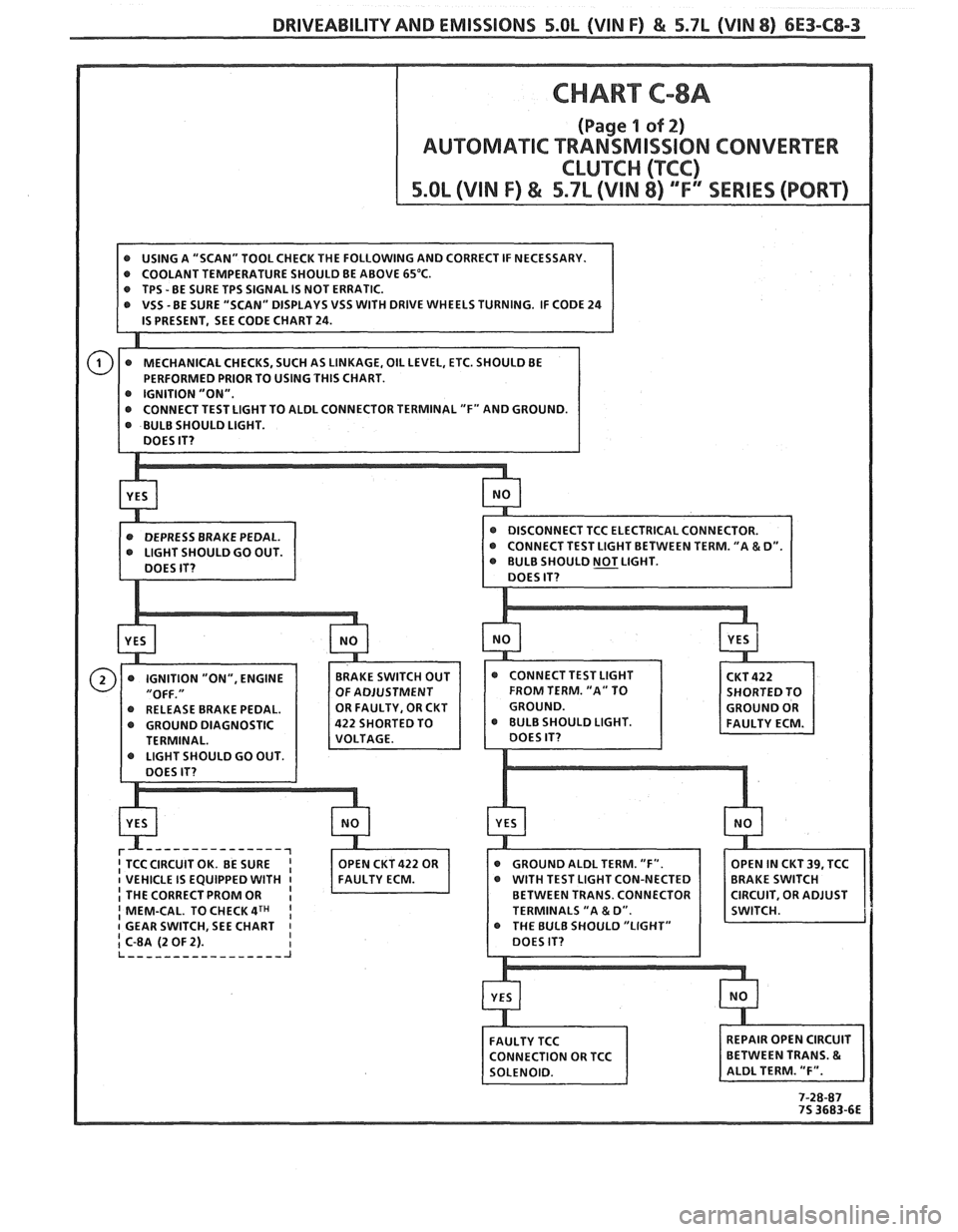
DRIVEABILITY AND EMISSIONS 5.OL (VIN F) & 5.7L (VIN 8) 6E3-C8-3
DRIVE WHEELS TURNING. IF CODE 24
OULD GO OUT.
Page 945 of 1825
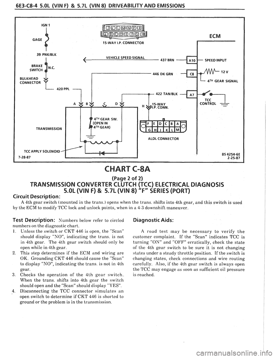
6E3-C8-4 5.OL (\/IN F) & 5.7b (VIN 8) DRIVEABILITY AND EMISSIONS
15-WAY I.P. CONNECTOR
SPEED INPUT
4TH GEAR SIGNAL
4TH GEAR SW.
TRANSMISSION
ALDL CONNECTOR
APPLY SOLENOID
CHART C-8A
(Page 2 of 2)
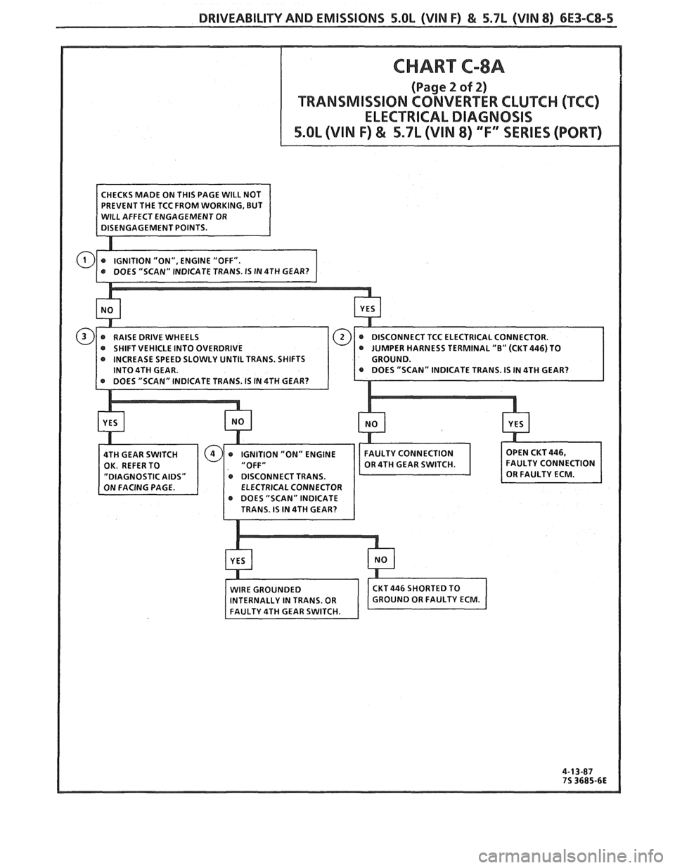
TRANSMISSION CONVERTER CLUTCH (TCC) ELECTRICAL DIAGNOSIS
5.OL (VIN F) & 5.7L (VIN 8) "F" XRlES (PORT)
Circuit Description:
A 4th gear switch (mounted in the trans.) opens when the trans. shifts into 4th gear, and this switch is used
by the ECM to modify TCC lock and unlock points, when in a 4-3 downshift maneuver.
Test Description: Numbers below refer to circled
numbers on the diagnostic chart.
1. Unless the switch or CKT 446 is open, the "Scan"
should display "NOJ', indicating the trans. is not
in 4th gear. The 4th gear switch should only he
open while in 4th gear.
2. This step determines if the ECM and wiring are
OK. Grounding CKT 446 should cause the "Scan"
to display "NO", indicating the trans. is not in 4th
gear.
3. Checks the operation of the 4th gear switch.
When the trans, shifts into 4th gear the switch
should open and the "Scan" should display "YES".
4. Disconnecting the TCC connector sin~ulates an
open switch to determine if CKT 446 is shorted to
ground or the problem is in the transmission.
Diagnostic Aids:
A road test may be necessary to verify the
customer complaint.
If the "Scan" indicates TCC is
turning
"ON" and "OFF" erratically, check the state
of the 4th gear switch to be sure it is not changing
states under a steady throttle position. If the switch is
changing states, check connections and wire routing
carefully. Also, if the 4th gear switch is always open
the
'l'CC may engage as soon as sufficient oil pressure
is reached.
Page 946 of 1825
DRIVEABILIW AND EMISSIONS 5.OL (VIN F) & 5.7L (VIN 8) 6E3-C8-5
TCC ELECTRICAL CONNECTOR.
@ SHIFT VEHICLE INTO OVERDRIVE NESS TERMINAL "0" (CKT446) TO
INCREASE SPEED SLOWLY UNTIL TRANS. SHIFTS
INTO 4TH GEAR.
CAL CONNECTOR
DOES "SCAN" INDICATE
Page 947 of 1825
6E3-C8-6 5.OL (VIN F) & 5.7L (WIN 8) DRIVEABILITY AND EMISSIONS
15-WAY I.P. CONNECTOR
SHIFT LIGHT
CONTROL DRIVER
INSTRUMENT PANEL
CHART C-8B
NlR SI-IIFT LIGHT CHECK
5.OL (VIN F) "F" "SERIES (PORT)
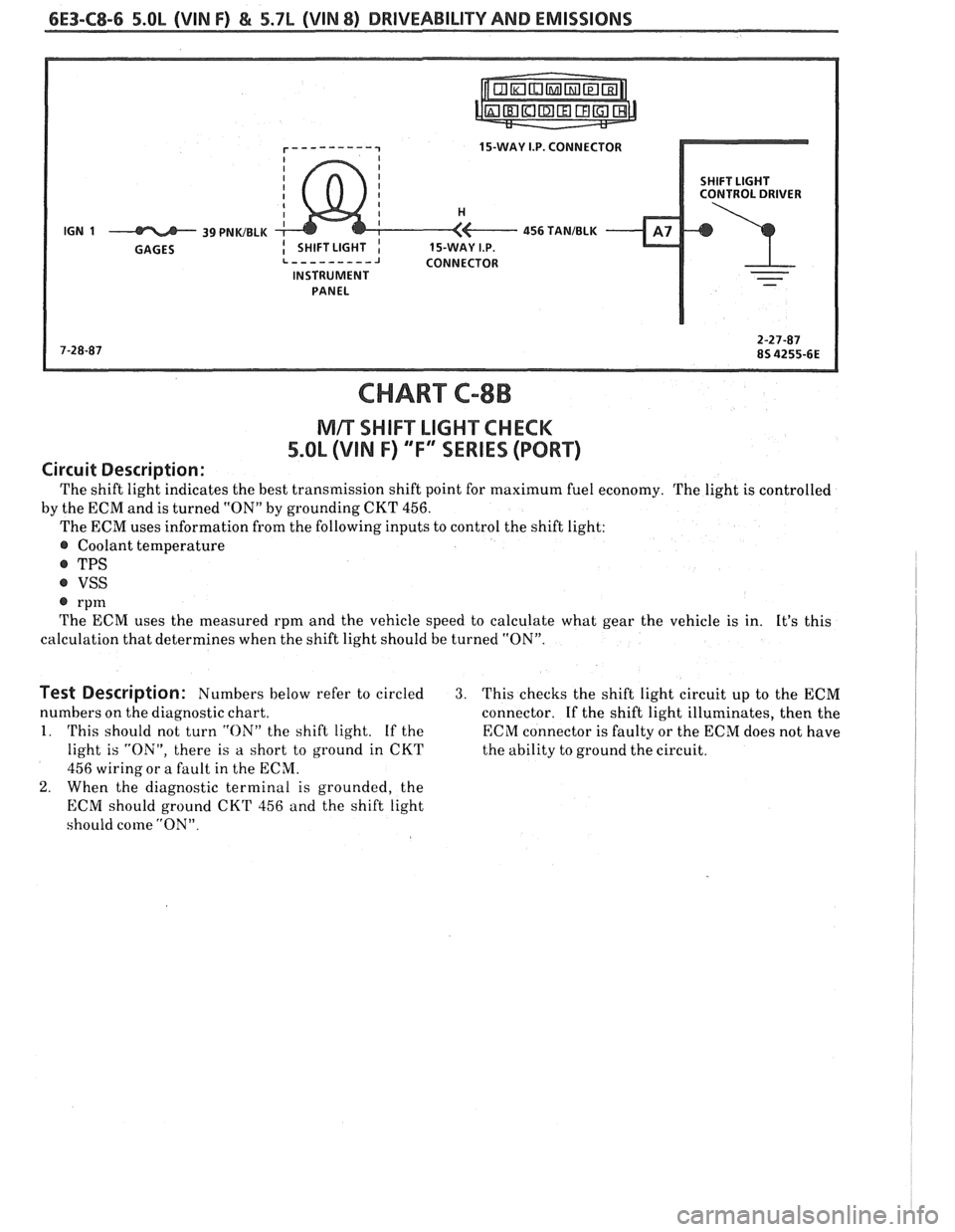
Circuit Description:
The shift light indicates the best transmission shift point for maximum fuel economy. The light is controlled
by the ECM and is turned
"ON" by grounding CKT 456.
The ECM uses information from the following inputs to control the shift light:
@ Coolant temperature
@ TPS
@ VSS
@ rpm
The ECM uses the measured rpm and the vehicle speed to calculate what gear the vehicle is in. It's this
calculation that determines when the shift light should be turned "ON".
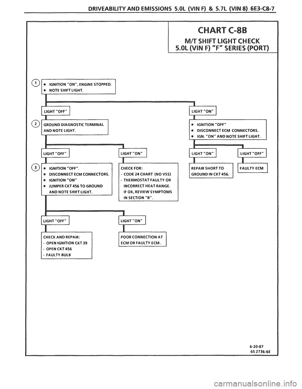
Test Description: Numbers below refer to circled 3. This checks the shift light circuit up to the ECM
numbers on the diagnostic chart.
connector.
If the shift light illuminates, then the
1. This should not turn "ON" the shift light. If the ECM connector is faulty or the ECM does not have
light is "ON", there is a short to ground in CKT
the ability to ground the circuit.
456 wiring or a fault in the ECM.
2. When the diagnostic terminal is grounded, the
ECM should ground
CKT 456 and the shift light
should come
"ON".
Page 948 of 1825
DRIVEABILITVAND EMISSIONS 5.OL (VIN F) & 5.7L (VIN 8) 6E3-C8-7
@ DISCONNECT ECM CONNECTORS.
@ DISCONNECT ECM CONNECTORS - CODE 24 CHART (NO VSS)
- THERMOSTAT FAULTY OR
INCORRECT HEAT RANGE.
IF OK, REVIEW SYMPTOMS
CHECK AND REPAIR: POOR
CONNECTION AT
- OPEN IGNITION CKT 39
- OPEN CKT 456
Page 949 of 1825

BLANK
Page 950 of 1825
DRlVEABlLlPV AND EMISSIONS 5.OL (VIN F) & 5.7L (VIN 8) 6E3-C"1-1
SECTION Cl2
COOLING FAN CONTROL
CONTENTS
GENERAL DESCRIPTION ................ C12-I DIAGNOSIS ......................... C1Z-1
OPERATION ..................... .. C12-1 ON-CARSERVICE ..................... C12-1
PARTS INFORMATION ................. C12-1
GENERAL DESCRIPIION DlAGNODlS
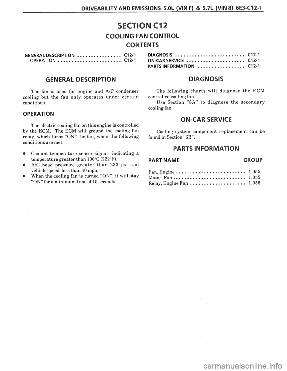
The fan is used for engine and AIC condenser
cooling but the fan only operates under certain
conditions. The
following charts will diagnose the ECM
controlled cooling fan.
Use
Sect.ion "8A" to diagnose the secondary
cooling fan.
OPERATION
ON-CAR SERVICE
The electric cooling fan on this engine is controlled
by the ECM. The ECM will ground the cooling fan
relay, which turns "ON" the fan, when the following
conditions are met.
@ Coolant temperature sensor signal indicating a
temperature greater than 106°C
(222°F).
@ AIC head pressure greater than 233 psi and
vehicle speed less than 40 mph.
When the cooling fan is turned "ON", it will stay
"ON" for a minimum time of 15 seconds. Cooling
system component replacement can be
found in Section
"6B".
PARTS INFORMATION
PART NAME GROUP
......................... Fan, Engine 1.055
......................... Motor, Fan. 1.055
.................... Relay, Engine Fan 1.055