check engine RENAULT KANGOO 1997 KC / 1.G Engine And Peripherals User Guide
[x] Cancel search | Manufacturer: RENAULT, Model Year: 1997, Model line: KANGOO, Model: RENAULT KANGOO 1997 KC / 1.GPages: 208
Page 45 of 208
TOP AND FRONT OF ENGINE
Timing belt
11
REFITTING
Check that the pin Mot. 1054 is in place.
Fit the timing belt by aligning the belt markings
with those of the camshaft, injection pump and
crankshaft sprockets.
13096R
Tension the timing belt by tightening a bolt ( A )
on the inner timing housing.
Fit tool Mot. 1273 and tension the belt until the
fitting value is reached (see section 07 "Timing
belt tension").
13094R
Tighten the tension wheel nut to 5 daN.m.
NOTE : it is essential to tighten the tension wheel
nut to a torque of 5 daN.m to avoid any slacke-
ning which may bring about a deterioration in the
engine.
Replace the crankshaft pulley bolt.
Refit the crankshaft pulley , being sure to tighten
the bolt to a torque of 2 daN.m with an angle of
115° ± 15°.
Refitting is the reverse of removal.
Refit the accessories belt (see section 07
"Accessories belt tension").
NOTE : Never refit a belt once it has been remo-
ved, but replace it.
F8Q Engine
11-10
Page 46 of 208
12mm torx socket
Angular tightening wrench
TOP AND FRONT OF ENGINE
Cylinder head gasket
11
SPECIAL TOOLING REQUIRED
Mot. 591-04 Angle wrench for tightening
cylinder head and index
Mot. 1202 Hose clip pliers
Mot. 1273 Tool for checking belt tension
Mot. 1379 Tool for securing engine to
subframe
EQUIPMENT REQUIRED
TIGHTENING TORQUES (in daN.m)
Crankshaft output mounting bolt 2 + 90°
Mounting bolt for front right suspended
engine mounting on engine 6.2
Mounting bolt for front right suspended
engine mounting on vehicle body 6.2
Timing belt tension wheel nut 5
Wheel bolts 9
REMOVAL
Put the vehicle on a 2 post lift.
Remove the bonnet, and the right hand wheel .
Disconnect the battery.
Drain the cooling circuit.
Fit the engine support tool, Mot. 1379.Remove:
- the timing belt (see method described in
section 11 "Timing belt"),
- the dipstick,
- the brake servo pipe,
- the air filter,
- the accelerator cable,
- the fuel supply and return pipes level with the
timing belt cover on the cylinder head
D7F Engine
11-11
Page 49 of 208
TOP AND FRONT OF ENGINE
Cylinder head gasket
11
92076S
CLEANING
It is very important not to scratch the gasket faces
of the aluminium components.
Use the Décapjoint product to dissolve any part of
the gasket which remains attached.
Apply the product to the parts to be cleaned; wait
about ten minutes, then remove it using a
wooden spatula.
Wear gloves whilst carrying out this operation.
Care must be taken whilst carrying out this ope-
ration in order to avoid any foreign bodies ente-
ring the oilways supplying oil under pressure to
the camshaft (oilways are located both in the cy-
linder block and the cylinder head).
Failure to follow to this advice could lead to the
blocking of the jets and thus cause rapid deterio-
ration of the cams and tappets.
CHECKING THE GASKET FACE
Check for gasket face bow using a straight edge
and a set of shims .
Maximum deformation : 0.05 mm.
No regrinding of the cylinder head is permitted.
REFITTING
The cylinder head is centred by two dowels at the
rear of the engine.
REMINDER: in order to obtain the correct tighte-
ning of the bolts, use a syringe to remove any oil
which may have entered the cylinder head moun-
ting bolt holes .
Grease the threads and under the bolt heads with
engine oil.
Adjustment of the valve rockers and tightening
of the cylinder head should be carried out when
the engine is cold. D7F Engine
11-14
Page 52 of 208
TOP AND FRONT OF ENGINE
Cylinder head gasket
11
SPECIAL TOOLING REQUIRED
DEPOSE
Place the vehicle on a 2 post lift .
Disconnect the battery.
Remove :
- the bonnet ,
- the timing belt (see method described in sec-
tion 11, "Timing belt ").
Drain the cooling circuit through the lower radia-
tor hose.
Fit tool Mot. 1159 between the engine subframe
and the cylinder block.
99024R2
EQUIPMENT REQUIRED
Engine support tool
55mm torx socket
Mot. 588 Retaining bracket
Mot. 591-02 Index
Mot. 591-04 Angle tightening angular
wrench
Mot. 1159 Tool for retaining engine on
subframe
Mot. 1202 Hose clip pliers
Mot. 1273 Tool for checking belt tension
Mot. 1311-06 Tool for removing fuel pipe
Tension wheel nut 5
Crankshaft pulley bolt 2 + 68° ± 6°
Bolt for suspended engine mounting 6.2
cover
Nut for suspended engine mounting cover 4.4
Wheel bolts 9
TIGHTENING TORQUES (in daN.m or /and °)
E7J Engine
11-17
Page 56 of 208
TOP AND FRONT OF ENGINE
Cylinder head gasket
11
CHECKING THE GASKET FACE
Check for gasket face bow, using a straight edge
and a set of shims.
Maximum deformation: 0.05 mm.
No regrinding of the cylinder head is permitted.
REFITTING (special notes)
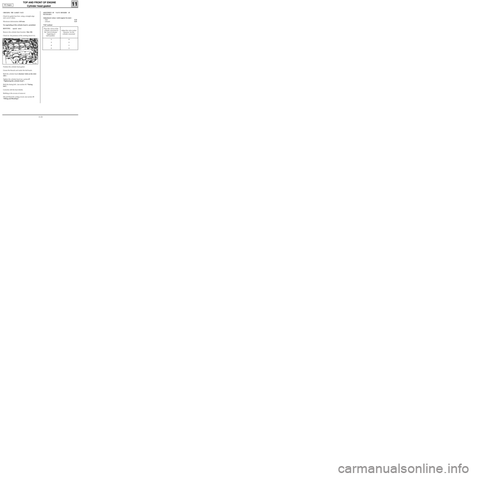
Remove the cylinder liner brackets Mot. 588.
Check for the presence of the centring dowel (A).
98713R1
Position the cylinder head gasket.
Grease the threads and under the bolt heads .
Refit the cylinder head (shortest bolts on the inlet
side ).
Tighten the cylinder head (see section 07
"Tightening the cylinder head").
Refit the timing belt , (see section 11 "Timing
belt").
Correctly refit the heat shields.
Refitting is the reverse of removal.
Fill and bleed the cooling circuit, (see section 19
"Filling and Bleeding").
ADJUSTMENT OF VALVE ROCKERS (IF
NECESSARY)
Adjustment values (cold engine) (in mm) :
- inlet0.10
- exhaust0.25
"Tilt" method
E7J Engine
Place the valves of the
cylinder concerned in
the "end of exhaust-
beginning of
inlet"position Adjust the valve rocker
clearance for the
cylinder concerned
14
32
41
23
11-21
Page 58 of 208
TOP AND FRONT OF ENGINE
Cylinder head gasket
11
SPECIAL TOOLING REQUIRED
REMOVAL
Place the vehicle on a two post lift .
Disconnect the battery.
Remove :
- the bonnet,
- the timing belt (see method described in
section 11 "Timing belt").
Drain the cooling circuit via the lower radiator
hose.
EQUIPMENT REQUIRED
Engine support tool
55mm torx socket
Mot. 251-01 Dial gauge support tool
Mot. 252-01 Plate for measuring piston
protrusion
Mot. 591-02 Index
Mot. 591-04 Angular tightening wrench
Mot. 1054
TDC pin
Mot. 1159 Tool for mounting engine on
subframe
Mot. 1202 Hose clip pliers
Mot. 1273 Tool for checking belt tension
Mot. 1311-06 Tool for removing fuel pipe
Tension wheel nut 5
Crankshaft pulley bolt 2 + 115° ± 15°
Bolt for suspended engine mounting cover 6.2
Nut for suspended engine mounting cover 4.4
Wheel bolts 9
TIGHTENING TORQUES (in daN.m or/and°)
99024R2
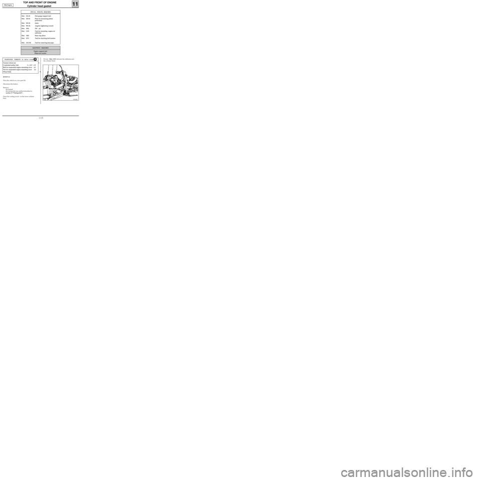
Fit tool Mot. 1159 between the subframe and
the cylinder block. F8Q Engine
11-23
Page 62 of 208
TOP AND FRONT OF ENGINE
Cylinder head gasket
11
Wear gloves whilst carrying out this operation.
99180S
CHECKING THE GASKET FACE
Check for gasket face bow, using a straight edge
and a set of shims.
Maximum deformation: 0.05 mm.
No regrinding of the cylinder head is permitted.
Check the cylinder head for cracks.
F8Q Engine
CLEANING
It is very important not to scratch the gasket faces
of the aluminium components.
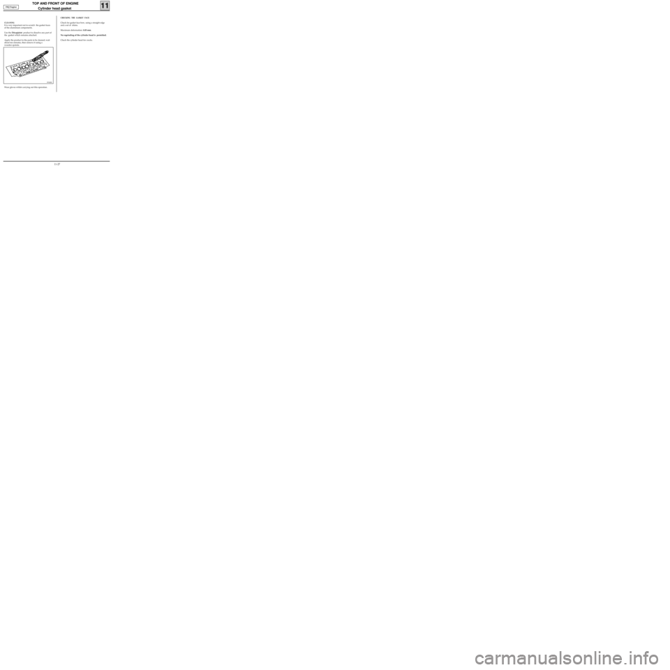
Use the Décapjoint product to dissolve any part of
the gasket which remains attached.
Apply the product to the parts to be cleaned; wait
about ten minutes, then remove it using a
wooden spatula.
11-27
Page 63 of 208
TOP AND FRONT OF ENGINE
Cylinder head gasket
11
REFITTING (special notes)
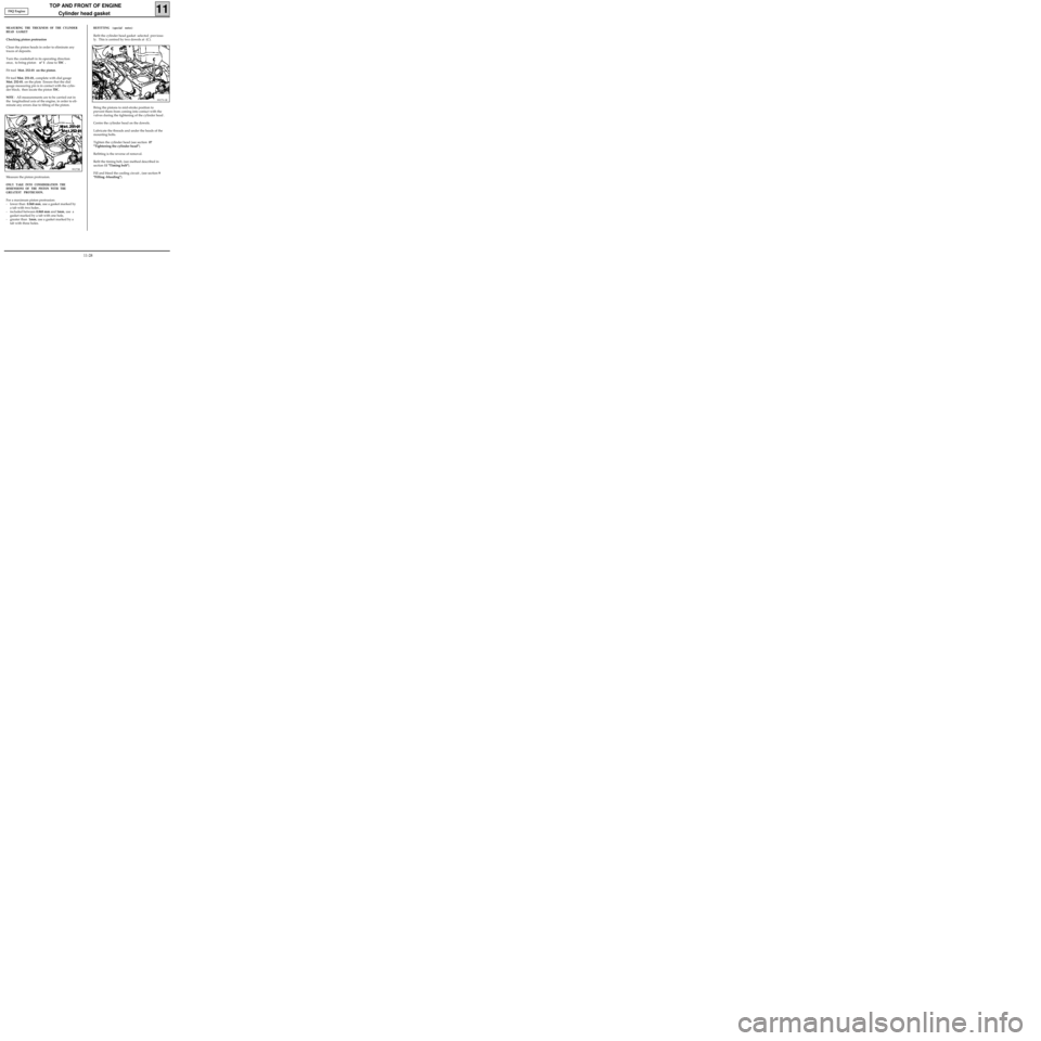
Refit the cylinder head gasket selected previous-
ly. This is centred by two dowels at (C).
99173-1R
Bring the pistons to mid-stroke position to
prevent them from coming into contact with the
valves during the tightening of the cylinder head .
Centre the cylinder head on the dowels.
Lubricate the threads and under the heads of the
mounting bolts.
Tighten the cylinder head (see section 07
"Tightening the cylinder head").
Refitting is the reverse of removal.
Refit the timing belt, (see method described in
section 11 "Timing belt").
Fill and bleed the cooling circuit , (see section 9
"Filling -bleeding").
MEASURING THE THICKNESS OF THE CYLINDER
HEAD GASKET
Checking piston protrusion
Clean the piston heads in order to eliminate any
traces of deposits.
Turn the crankshaft in its operating direction
once, to bring piston n° 1 close to
TDC .
Fit tool Mot. 252-01 on the piston.
Fit tool Mot. 251-01, complete with dial gauge
Mot. 252-01. on the plate Ensure that the dial
gauge measuring pin is in contact with the cylin-
der block; then locate the piston
TDC.
NOTE
: All measurements are to be carried out in
the longitudinal axis of the engine, in order to eli-
minate any errors due to tilting of the piston.
99173R
Measure the piston protrusion.
ONLY TAKE INTO CONSIDERATION THE
DIMENSIONS OF THE PISTON WITH THE
GREATEST PROTRUSION.
For a maximum piston protrusion:
- lower than 0.868 mm, use a gasket marked by
a tab with two holes ,
- included between 0.868 mm and 1mm, use a
gasket marked by a tab with one hole,
- greater than 1mm, use a gasket marked by a
tab with three holes. F8Q Engine
11-28
Page 64 of 208
TOP AND FRONT OF ENGINE
Replacement of valve adjusters
11
SPECIAL TOOLING REQUIRED
Mot. 1366-01 Tool for removing valve adjusters
(additional item to Mot. 1366)
TIGHTENING TORQUES (in daN.m)
Studs for mounting manifolds on
cylinder head 1
Nut for mounting manifolds on
cylinder head 2.7
Mounting bolt for strut on inlet manifold 2.5
Mounting bolt for strut on cylinder block 2.5
Place the vehicle on a two-post lift
Disconnect the battery.
CHECKING THE VALVE CLEARANCE
Remove the air filter housing along with the cy-
linder head cover.
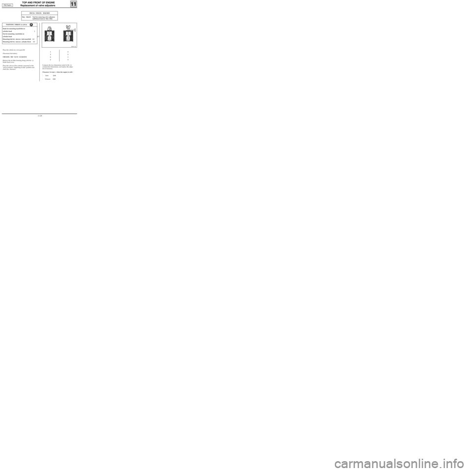
Place the valves of the cylinder concerned at the
"end of exhaust - beginning of inlet" position and
check the clearance .
86911-1S
1
3
4
24
2
1
3
Compare the two dimensions noted to the re-
commended dimensions, and replace the adjus-
ters if necessary .
Clearance ( in mm ), when the engine is cold :
- Inlet: 0.10
- Exhaust :0.25 F8Q Engine
11-29
Page 87 of 208
FUEL SUPPLY
Pump flow
13
Petrol
engines
96093R2
SPECIAL TOOLING REQUIRED
Mot. 1265 Pliers for removing quick release
unions
EQUIPMENT REQUIRED
2 000 ml measuring cylinder
It is advised to check the pump supply flow
through the fuel return pipe connected to the
pump-fuel sender unit assembly.
IMPORTANT
During this operation, it is essential :
• to refrain from smoking and handling incan-
descent objects close to the working area,
• to take precautions against possible fuel
projections which may occur due to the resi-
dual pressure in the supply pipes when they
are removed.
CHECKING THE PUMP FLOW
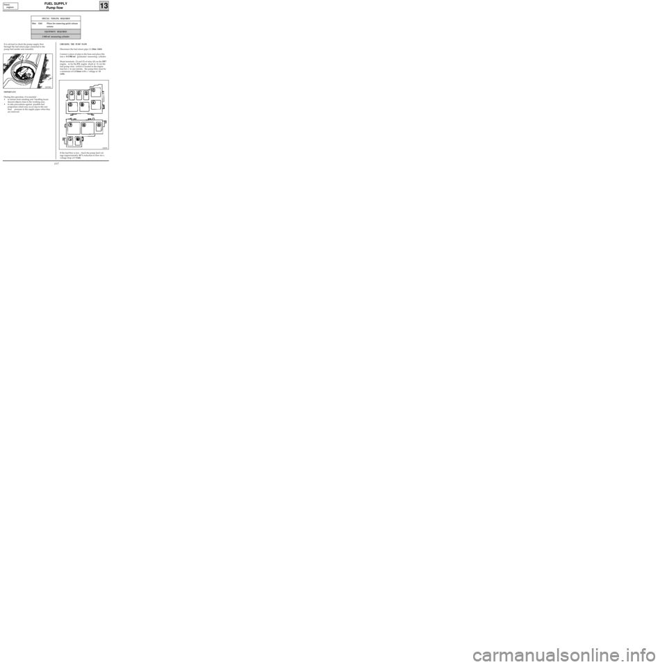
Disconnect the fuel return pipe (1) (Mot. 1265).
Connect a piece of pipe to the hose and place this
into a 0-2 000 ml graduated measuring cylinder.
Shunt terminals (3) and (5) of relay (K) on the DF7
engine, or for the
E7J engine shunt at (L) on the
fuel pump relay (which is located in the engine
fuse box ). In one minute, the pump flow must be
a minimum of 1.3 litres with a voltage of 12
volts.
If the fuel flow is low, check the pump feed vol-
tage (approximately 10 % reduction in flow for a
voltage drop of 1 Volt)
12839S
13-7