wiring RENAULT KANGOO 1997 KC / 1.G Foult Finding - Injection User Guide
[x] Cancel search | Manufacturer: RENAULT, Model Year: 1997, Model line: KANGOO, Model: RENAULT KANGOO 1997 KC / 1.GPages: 363
Page 59 of 363
JF5111.0
INJECTION
Fault finding - Interpretation of XR25 bargraphs17
E7J 780
engine
Erase the computer memory using G0**.
Try to start the engine. Switch the ignition on, then deal with the other faults.
Remember to carry out a status and parameter check.AFTER REPAIR
Bargraph 2 RH side illuminatedFiche n° 27 side 1/2
IMMOBILISER CIRCUIT
XR25 aid:*22 = 1 dEF CO, CC- or CC+ line 37 on the computer
*22 = 2 dEF Refer to the immobiliser fault finding
2
Ignore this bargraph if the vehicle is not fitted with an immobiliser.NOTES
Connect the bornier in place of the computer and check the insulation, continuity and that there is no
interference resistance on the wiring on track 37 of the computer.
Repair if necessary.
If the fault persists, refer to the immobiliser fault finding.
17-11
Page 89 of 363
Check the insulation and continuity of the wiring:
Fuel pump relay L5 Impact sensor
Impact sensor C1 Fuel pump
Repair if necessary.
Check the 30A fuel pump fuse.
Check the insulation and continuity of the wiring:
Fuel pump fuse L3 Fuel pump relay
Repair if necessary.
JF5111.0
INJECTION
Fault finding - Status and parameter interpretation17
E7J 780
engine
AFTER REPAIRStart the status and parameter check again from the beginning.
DIAG 6
Fiche n° 27
FUEL PUMP
XR25 aid:The command mode should cause the fuel pump to operate
No fault bargraphs should be illuminated.NOTES
Check the hygiene and presence of earth on track C2 of the fuel pump.
If + 12 V is not reaching the fuel pump, replace the fuel pump relay.
If + 12 V is reaching the fuel pump, replace the fuel pump.
Check the impact sensor is correctly clipped in.
17-41
Page 91 of 363
The pinking sensor should give a signal which is variable and not zero, to prove that it is recording the
mechanical vibrations of the engine.
If the signal is zero:
- Check the sensor is correctly screwed in.
- Check the insulation and continuity of the wiring:
Computer 8 2 Pinking sensor
Computer 44 1 Pinking sensor
Computer 2 Pinking sensor screening
If necessary, replace the sensor.
JF5111.0
INJECTION
Fault finding - Status and parameter interpretation17
E7J 780
engine
AFTER REPAIRStart the status and parameter check again from the beginning.
DIAG 8
Fiche n° 27
ANTI-PINKING CIRCUIT
XR25 aid:# 13 is not zero and variable for fast idle or under load
No fault bargraphs should be illuminated.NOTES
17-43
Page 95 of 363

JF5111.0
INJECTION
Fault finding - Status and parameter interpretation17
E7J 780
engine
AFTER REPAIRStart the status and parameter check again from the beginning.
DIAG 12
Fiche n° 27
IMMOBILISER
XR25 aid:Status BG 3RH illuminated, ignition on
No fault bargraphs should be illuminated.NOTES
Check the insulation and continuity of the wiring for track 37 on the injection computer.
If the fault persists, refer to the immobiliser fault finding.
17-47
Page 121 of 363
JSA051.0
INJECTION
Fault finding - Introduction
17
D7F 710
engine -
35 tracks
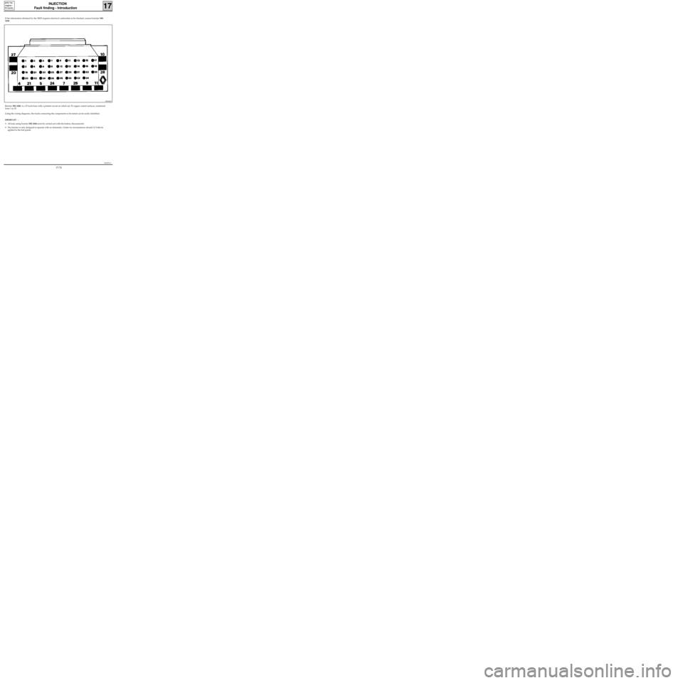
If the information obtained by the XR25 requires electrical continuities to be checked, connect bornier MS
1048.
Bornier MS 1048 is a 35 track base with a printed circuit on which are 35 copper coated surfaces, numbered
from 1 to 35.
Using the wiring diagrams, the tracks connecting the components to be tested can be easily identified.
IMPORTANT :
• All tests using bornier MS 1048 must be carried out with the battery disconnected.
• The bornier is only designed to operate with an ohmmeter. Under no circumstances should 12 Volts be
applied to the test points.
89024S3
17-76
Page 130 of 363
JSA051.0
INJECTION
Fault finding - Interpretation of XR25 bargraphs17
D7F 710
engine -
35 tracks
Erase the computer memory using G0**.
Try to start the engine. Switch the ignition on, then deal with the other faults.
Remember to carry out a status and parameter check.AFTER REPAIR
Bargraph 2 RH side illuminatedFiche n° 27 side 1/2
IMMOBILISER CIRCUIT
XR25 aid:*22 = 1 dEF CO, CC- or CC+ line 30 on the computer
*22 = 2 dEF Refer to the immobiliser fault finding
2
Ignore this bargraph if the vehicle is not fitted with an immobiliser.NOTES
Connect the bornier in place of the computer and check the insulation, continuity and that there is no
interference resistance on the wiring on track 30 of the computer.
Repair if necessary.
If the fault persists, refer to the immobiliser fault finding.
17-85
Page 159 of 363
Check the insulation and continuity of the wiring:
Fuel pump relay 5 Impact sensor
Impact sensor C1 Fuel pump
Repair if necessary.
Check the 25A fuel pump fuse.
Check the insulation and continuity of the wiring:
Fuel pump fuse 3 Fuel pump relay
Repair if necessary.
JSA051.0
INJECTION
Fault finding - Status and parameter interpretation17
D7F 710
engine -
35 tracks
AFTER REPAIRStart the status and parameter check again from the beginning.
DIAG 6
Fiche n° 27
FUEL PUMP
XR25 aid:The command mode should cause the fuel pump to operate
No fault bargraphs should be illuminated.NOTES
Check the hygiene and presence of earth on track C2 of the fuel pump.
If + 12 V is not reaching the fuel pump, replace the fuel pump relay.
If + 12 V is reaching the fuel pump, replace the fuel pump.
17-114
Page 161 of 363
The pinking sensor should give a signal which is variable and not zero, to prove that it is recording the
mechanical vibrations of the engine.
If the signal is zero:
- Check the sensor is correctly screwed in.
- Check the insulation and continuity of the wiring:
Computer 1 2 Pinking sensor
Computer 15 1 Pinking sensor
Computer 16 Pinking sensor screening
If necessary, replace the sensor.
JSA051.0
INJECTION
Fault finding - Status and parameter interpretation17
D7F 710
engine -
35 tracks
AFTER REPAIRStart the status and parameter check again from the beginning.
DIAG 8
Fiche n° 27
ANTI-PINKING CIRCUIT
XR25 aid:# 13 is not zero and variable for fast idle or under load
No fault bargraphs should be illuminated.NOTES
17-116
Page 165 of 363

JSA051.0
INJECTION
Fault finding - Status and parameter interpretation17
D7F 710
engine -
35 tracks
AFTER REPAIRStart the status and parameter check again from the beginning.
DIAG 12
IMMOBILISERFiche n° 27
XR25 aid:Status BG 3RH, incorrect illumination
No fault bargraphs should be illuminated.NOTES
Check the insulation and continuity of the wiring for track 30 on the injection computer.
If the fault persists, refer to the immobiliser fault finding.
17-120
Page 191 of 363
JSA052.0
INJECTION
Fault finding - Introduction
17
D7F 710
engine -
55 tracks
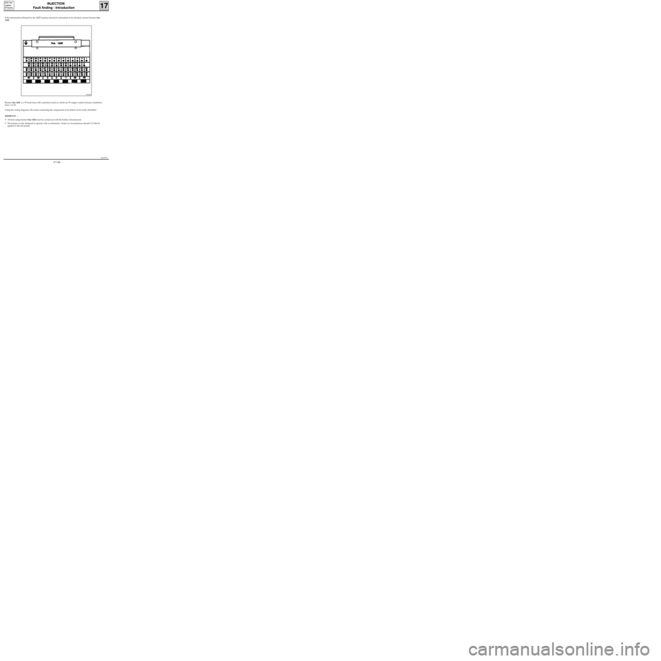
If the information obtained by the XR25 requires electrical continuities to be checked, connect bornier Sus
1228.
Bornier Sus 1228 is a 55 track base with a printed circuit on which are 55 copper coated surfaces, numbered
from 1 to 55.
Using the wiring diagrams, the tracks connecting the components to be tested can be easily identified.
IMPORTANT :
• All tests using bornier Sus 1228 must be carried out with the battery disconnected.
• The bornier is only designed to operate with an ohmmeter. Under no circumstances should 12 Volts be
applied to the test points.
97434S
17-148