wiring RENAULT KANGOO 1997 KC / 1.G Foult Finding - Injection Owner's Manual
[x] Cancel search | Manufacturer: RENAULT, Model Year: 1997, Model line: KANGOO, Model: RENAULT KANGOO 1997 KC / 1.GPages: 363
Page 200 of 363
JSA052.0
INJECTION
Fault finding - Interpretation of XR25 bargraphs17
D7F 710
engine -
55 tracks
Erase the computer memory using G0**.
Try to start the engine. Switch the ignition on, then deal with the other faults.
Remember to carry out a status and parameter check.AFTER REPAIR
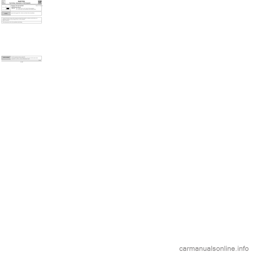
Bargragh 2 RH side illuminated Fiche n° 27 side 1/2
IMMOBILISER CIRCUIT
XR25 aid:*22 = 1 dEF CO, CC- or CC+ line 37 of the computer
*22 = 2 dEF Refer to the immobiliser fault finding section
2
Ignore this bargraph if the vehicle is not fitted with an immobiliser.NOTES
Connect the bornier in place of the computer and check the insulation, continuity and that there is no
interference resistance on the wiring on track 37 of the computer.
Repair if necessary.
If the fault persists, refer to the immobiliser fault finding.
17-157
Page 229 of 363
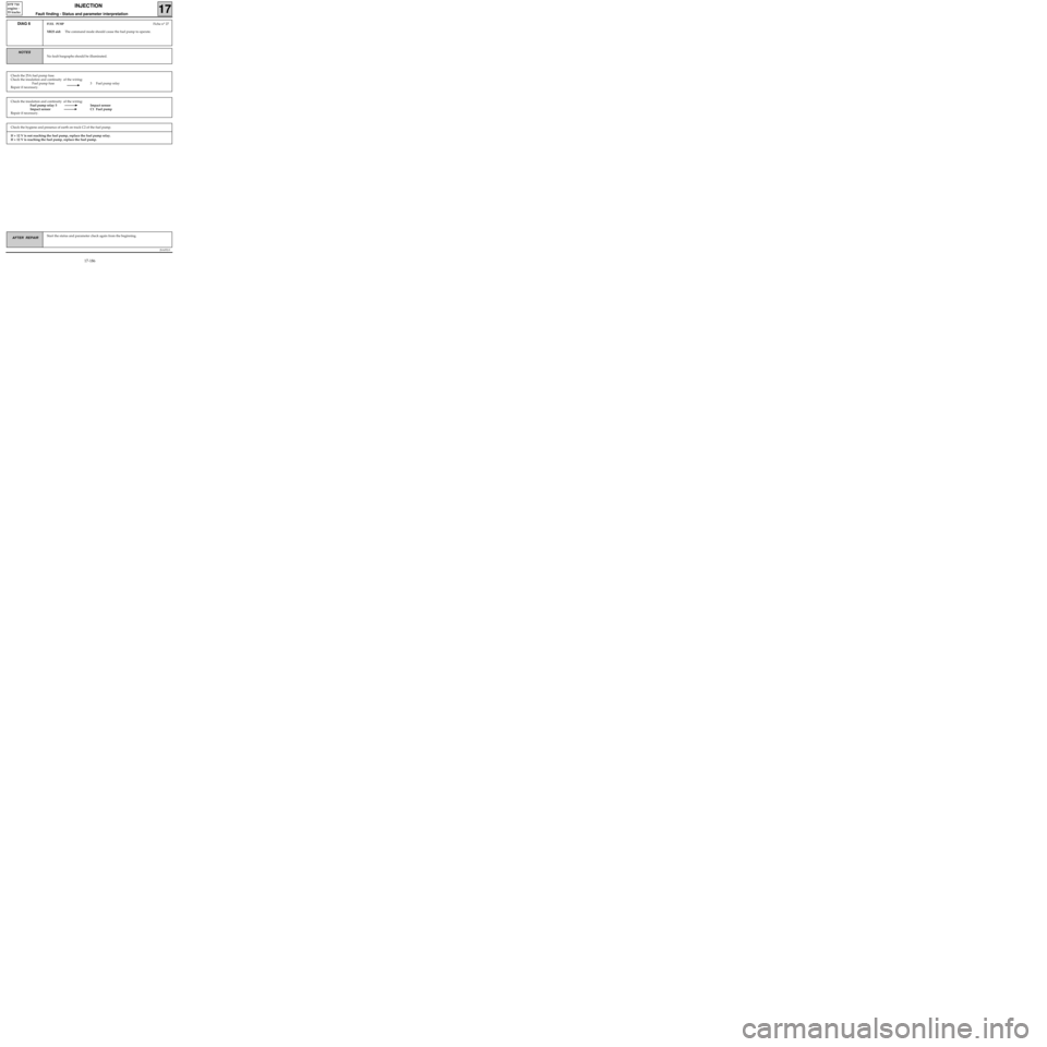
Check the insulation and continuity of the wiring:
Fuel pump relay 5 Impact sensor
Impact sensor C1 Fuel pump
Repair if necessary.
Check the 25A fuel pump fuse.
Check the insulation and continuity of the wiring:
Fuel pump fuse 3 Fuel pump relay
Repair if necessary.
JSA052.0
INJECTION
Fault finding - Status and parameter interpretation17
D7F 710
engine -
55 tracks
AFTER REPAIRStart the status and parameter check again from the beginning.
DIAG 6FUEL PUMPFiche n° 27
XR25 aid: The command mode should cause the fuel pump to operate.
No fault bargraphs should be illuminated.
NOTES
Check the hygiene and presence of earth on track C2 of the fuel pump.
If + 12 V is not reaching the fuel pump, replace the fuel pump relay.
If + 12 V is reaching the fuel pump, replace the fuel pump.
17-186
Page 231 of 363
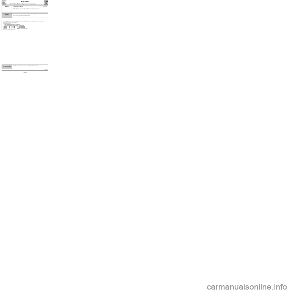
The pinking sensor should give a signal which is variable and not zero, to prove that it is recording the
mechanical vibrations of the engine.
If the signal is zero:
- Check the sensor is correctly screwed in.
- Check the insulation and continuity of the wiring:
Computer 54 2 Pinking sensor
Computer 44 1 Pinking sensor
Computer 2 Pinking sensor screening
If necessary, replace the sensor.
JSA052.0
INJECTION
Fault finding - Status and parameter interpretation17
D7F 710
engine -
55 tracks
AFTER REPAIRStart the status and parameter check again from the beginning.
DIAG 8ANTI-PINKING CIRCUITFiche n° 27
XR25 aid:# 13 is not zero and variable for fast idle or under load
No fault bargraphs should be illuminated.
NOTES
17-188
Page 235 of 363
JSA052.0
INJECTION
Fault finding - Status and parameter interpretation17
D7F 710
engine -
55 tracks
AFTER REPAIRStart the status and parameter check again from the beginning.
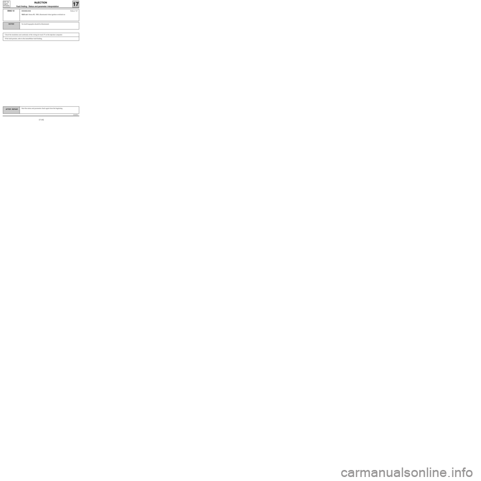
DIAG 12IMMOBILISERFiche n° 27
XR25 aid : Status BG 3RH, illuminated when ignition switched on
No fault bargraphs should be illuminated.NOTES
Check the insulation and continuity of the wiring for track 37 on the injection computer.
If the fault persists, refer to the immobiliser fault finding.
17-192
Page 262 of 363
B76531.0
ELECTRONICALLY CONTROLLED HYDRAULIC SYSTEMS
Fault finding - Introduction38
ABS BOSCH
5.3
CONDITIONS FOR APPLICATION FOR THE TESTS DEFINED IN THIS FAULT FINDING
The tests described in this fault finding are only to be applied when the wording of the fault corresponds
exactly to the display on the XR25 kit.
If a fault is dealt with because there is a flashing bargraph, the conditions for confirming the existence of an
actual fault (and the need to apply the fault finding ) can be found in the "Notes" or at the beginning of the
bargraph interpretation.
If a bargraph is only interpreted when it is permanently illuminated, the application of the recommended
tests in the fault finding when the bargraph is flashing will not allow you to determine the origin of the
memorisation of this fault. In this case, only a test of the wiring and the connections of the component in
question must be carried out (the fault is simply memorised as it was not present at the time of testing).
NOTE : The ignition must have been switched off before the XR25 kit is used.
INDISPENSABLE TOOLING REQUIRED FOR OPERATIONS ON THE ABS SYSTEM
- XR25 kit.
- XR25 cassette n° 16 minimum.
Reminders :When there is intermittent fault memorisation, the ABS warning light will illuminate the next
time the vehicle is used until the car reaches 7.5mph (12 km/h). When the fault is memorised, a
counter relating to the fault is set at 40 . This value is reduced by one each time the ignition is
turned on if the fault is not present when the vehicle exceeds 7.5mph (12 km/h). When the
reading on the counter is equal to 1, it remains at 1 and the fault is not erased.
38-1
Page 266 of 363
B76531.0
ELECTRONICALLY CONTROLLED HYDRAULIC SYSTEMS
Fault finding - Interpretation of XR25 bargraphs
38
ABS BOSCH
5.3
After replacing the computer, carry out another XR25 test.AFTER REPAIR
Bargraph 1 left hand side illuminated
Power supply/computer
1
None.
NOTES
Fiche n° 53
Erase the computer memory, exit the fault finding (G13*) and switch off the ignition.
Carry out a new XR25 test. If the "power supply / computer" fault persists, replace the ABS computer.
Check the condition and position of the 60A ABS fuse in the engine connection unit (white mounting).
Ensure continuity between this fuse and tracks 17 and 18 of the computer connector (presence of positive
before ignition feed on both tracks). Check the tightness and condition of the battery terminals.
Check the connections on the 31 track connector of the ABS computer.
Check the ABS earths (above the hydraulic assembly) and visually check all the ABS wiring.
38-5
Page 268 of 363
B76531.0
ELECTRONICALLY CONTROLLED HYDRAULIC SYSTEMS
Fault finding - Interpretation of XR25 bargraphs
38
ABS BOSCH
5.3
Erase computer memory(GO**).
Carry out a road test followed by a check with the XR25 kit.AFTER REPAIR
Bargraph 6 left hand side illuminated
Front left wheel sensor circuit
6
None.
NOTES
Fiche n° 53
If the resistance is correct, check and ensure the continuity of the connection between the sensor
connector and the computer connector:
- between one track of the sensor connector and track 7 of the computer connector,
- between the other track of the sensor connector and track 6 of the computer connector.
Also check the insulation between these connections.
Carry out a visual inspection of the sensor wiring and check the quality of the connection on the 31 track
computer connector.
If all the checks are correct, reconnect the computer and the wheel speed sensor then erase the computer
memory.
Exit fault finding mode(G13*) and switch off the ignition.
Switch the ignition on and replace the sensor if the fault reappears.
If the fault reappears after replacing the sensor, replace the computer.
Check the connection and condition of the sensor connections.
If the connector is correct, check the resistance of the sensor at its connector..
Replace the sensor if its resistance is not approximately 1.6 Kohms (1,6 Kohms ± 320 ohms).
38-7
Page 269 of 363
B76531.0
ELECTRONICALLY CONTROLLED HYDRAULIC SYSTEMS
Fault finding - Interpretation of XR25 bargraphs
38
ABS BOSCH
5.3
Erase computer memory(GO**).
Carry out a road test followed by a check with the XR25 kit.AFTER REPAIR
Bargraph 6 Right hand side illuminated
Front right wheel sensor circuit
6
None.
NOTES
Fiche n° 53
If the resistance is correct , check and ensure the continuity of the connections between the sensor
connector and the computer connector :
- between one track of the sensor connector and track 3 of the computer connector,
- between the other track of the sensor connector and track 5 of the computer connector.
Also check the insulation between these connections.
Carry out a visual inspection of the sensor wiring and check the quality of the connections on the 31
track computer connector.
If all the checks are correct, reconnect the computer and the wheel speed sensor, then erase the
computer memory.
Exit the fault finding mode(G13*) and switch off the ignition.
Switch the ignition on and replace the sensor if the fault reappears .
If the fault reappears after replacing the sensor, replace the computer.
Check the connection and condition of the sensor connections.
If the connector is correct, check the resistance of the sensor at its connector.
Replace the sensor if its resistance is not approximately 1.6 Kohms (1.6 Kohms ± 320 ohms).
38-8
Page 270 of 363
B76531.0
ELECTRONICALLY CONTROLLED HYDRAULIC SYSTEMS
Fault finding - Interpretation of XR25 bargraphs
38
ABS BOSCH
5.3
Erase computer memory(GO**).
Carry out a road test followed by a check with the XR25 kit.AFTER REPAIR
Bargraph 7 left hand side illuminated
Rear left wheel sensor circuit
7
None.
NOTES
Fiche n° 53
If all checks are correct, reconnect the computer and wheel speed sensor, then erase the computer
memory.
Exit fault finding mode(G13*) and switch off the ignition.
Switch on the ignition and replace the sensor if the fault reappears.
If the fault reappears after replacing the sensor, replace the computer.
Check the connection and condition of the sensor connections.
Check the connections at the intermediate connection under the body (R101).
If the connector is correct, check the resistance of the sensor at its connector. Replace the sensor if the
resistance is not approximately 1.6 Kohms (1.6 Kohms ± 320 ohms).
If the resistance is correct, check and ensure the continuity of the connections between the sensor
connector and the computer connector :
- between one track of the sensor connector and track 8 of the computer connector (via track B of the
connector under the body R101),
- between the other track of the sensor connector and track 9 of the computer connector (via track A of
the connector under the body R101).
Also check the insulation between these connections.
Carry out a visual inspection of the sensor wiring and check the quality of the connections on the 31 track
computer connector.
38-9
Page 271 of 363
B76531.0
ELECTRONICALLY CONTROLLED HYDRAULIC SYSTEMS
Fault finding - Interpretation of XR25 bargraphs
38
ABS BOSCH
5.3
Erase computer memory(GO**).
Carry out a road test followed by a check with the XR25 kit.AFTER REPAIR
Bargraph 7 Right hand side illuminated
Rear right wheel sensor circuit
7
None.
NOTES
Fiche n° 53
If all checks are correct, reconnect the computer and the wheel speed sensor, then erase the computer
memory.
Exit fault finding mode(G13*) and switch off the ignition.
Switch on the ignition and replace the sensor if the fault reappears.
If the fault reappears after replacing the sensor, replace the computer.
Check the connection and condition of the sensor connections.
Check the connections at the intermediate connector under the body (R101).
If the connector is correct , check the resistance of the sensor at its connector.
Replace the sensor if its resistance is not approximately 1.6 Kohms (1.6 Kohms ± 320 ohms).
If the resistance is correct, check and ensure the continuity of the connections between the sensor
connector and the computer connector :
- between one track of the sensor connector and track 1 of the computer connector (via track D of the
connector under the body R101),
-between the other track of the sensor connector and track 2 of the computer connector (via track C of
the connector under the body R101).
Also check the insulation between these connections.
Carry out a visual inspection of sensor wiring and check the quality of the connections on the 31 track
computer connector.
38-10