RENAULT SCENIC 2000 J64 / 1.G Technical Note 3426A Repair Manual
Manufacturer: RENAULT, Model Year: 2000, Model line: SCENIC, Model: RENAULT SCENIC 2000 J64 / 1.GPages: 118, PDF Size: 1.5 MB
Page 61 of 118
Downloaded from www.Manualslib.com manuals search engine DIESEL EQUIPMENT
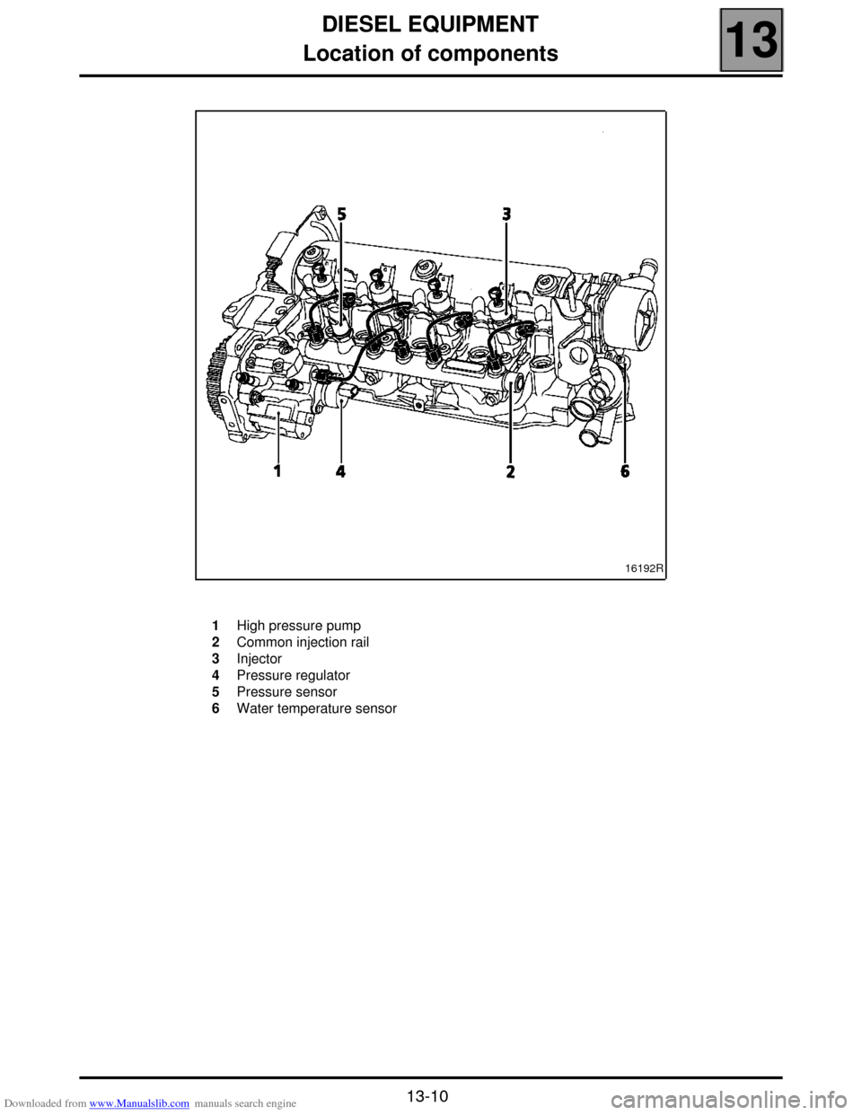
Location of components
13
13-10
16192R
1
2
3
4
5
6High pressure pump
Common injection rail
Injector
Pressure regulator
Pressure sensor
Water temperature sensor
Page 62 of 118
Downloaded from www.Manualslib.com manuals search engine DIESEL EQUIPMENT
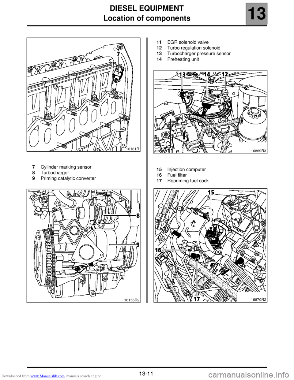
Location of components
13
13-11
16181R
7
8
9Cylinder marking sensor
Turbocharger
Priming catalytic converter
16155R2
11
12
13
14EGR solenoid valve
Turbo regulation solenoid
Turbocharger pressure sensor
Preheating unit
16869R3
15
16
17Injection computer
Fuel filter
Repriming fuel cock
16870R2
Page 63 of 118

Downloaded from www.Manualslib.com manuals search engine DIESEL EQUIPMENT
Injection warning light
13
13-12
Injection warning light
Vehicles using the high pressure diesel system are fitted with two injection warning lights used during the preheating
phase and in case of an injection fault (or engine overheating).
WARNING LIGHT PRINCIPLE
!When ignition is switched on, the preheating light is lit during the preheating phase and then goes out (see section
13 "Pre-postheating control").
!When there is a fault on the injection system the "fault" warning light lights up. These faults are:
– internal computer fault,
– engine speed fault (the vehicle doesn't start),
– main relay or low pressure fault (the vehicle doesn't start),
– injector fault,
–TDC sensor coherence fault and camshaft sensor,
– rail pressure sensor fault,
– rail pressure regulator fault,
– accelerator potentiometer fault,
– engine immobiliser fault,
– computer supply voltage fault,
– engine overheating.
NOTE: the OBD warning light (symbolised by an engine), visible when the ignition is switched on, is never visible
when the engine is running.
Page 64 of 118

Downloaded from www.Manualslib.com manuals search engine DIESEL EQUIPMENT
Immobiliser function
13
13-13
Immobiliser function
This vehicle is fitted with an engine immobiliser controlled by a random rolling code key recognition system.
REPLACING AN INJECTION COMPUTER
The injection computers are supplied without a code but they must all be programmed with one.
When the computer is replaced, the vehicle code must be programmed in and then a check must be made to ensure
that the immobiliser system is operational.
To do this, simply switch on the ignition for a few seconds without starting the engine then switch it of f. When the
ignition is off, the engine immobiliser function will be activated after approximately 10 seconds (red engine
immobiliser warning light flashes).
IMPORTANT:
With this engine immobiliser, the computer keeps its immobiliser code for life.
In addition, this system does not have a security code.
Consequently, it is forbidden to perform tests with computers borrowed from the stores or from another
vehicle which must then be returned.
It will no longer be possible to decode them.
Page 65 of 118

Downloaded from www.Manualslib.com manuals search engine DIESEL EQUIPMENT
Injection/air conditioning programming
13
13-14
Injection/air conditioning programming
INJECTION COMPUTER/AC COMPUTER CONNECTION
The compressor is of the variable cubic capacity type.
The injection calculator and the air conditioning calculator are linked by two leads:
– The power absorbed information tells the injection computer the output absorbed by the compressor. It is possible
to see the output absorbed using the diagnostic tool. When air conditioning is engaged the reading should be
between 250 and 5000 Watts.
– The connection from the injection computer to the air conditioning computer. This lead carries information on
whether starting the compressor is authorized or forbidden.
When the air conditioning function is selected, idling speed is modified to reach a maximum of 875 rpm.
IMPORTANT: the absorbed output is never equal to 0, whatever the status of the compressor, engaged or not. The
minimum value read is approximately 250 Watts.
Page 66 of 118

Downloaded from www.Manualslib.com manuals search engine DIESEL EQUIPMENT
Injection/air conditioning programming
13
13-15
COMPRESSOR OPERATION PROGRAMMING
During certain stages of operation, the diesel injection computer stops the compressor from functioning.
Engine start programming
The compressor is prevented from operating for 5 seconds after the engine has started.
Recovery of performance
When the position of the accelerator pedal is changed significantly and if the engine speed is less than 3000 rpm,
the compressor is prevented from operation for 5 seconds.
Recovery of output when the vehicle starts moving
If the position of the potentiometer is more than 50 % the engine speed is less than 2250 rpm and the vehicle speed
is below 20 km/h, the compressor is cut for 5 seconds.
Anti-stall protection
If the no load position is not detected, and the engine speed is less than 675 rpm. the compressor is disengaged. It
is engaged again after 5 seconds if the engine speed is increased.
Thermal protection programming
The compressor does not engage in cases where the coolant temperature is greater than + 112 °C.
Page 67 of 118
Downloaded from www.Manualslib.com manuals search engine DIESEL EQUIPMENT
Idle speed correction
13
13-16
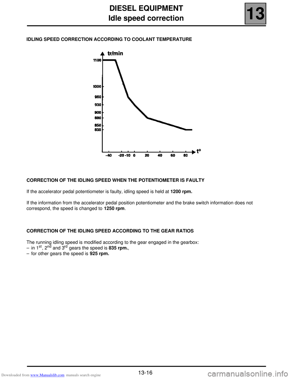
Idle speed correction
IDLING SPEED CORRECTION ACCORDING TO COOLANT TEMPERATURE
CORRECTION OF THE IDLING SPEED WHEN THE POTENTIOMETER IS FAULTY
If the accelerator pedal potentiometer is faulty, idling speed is held at 1200 rpm.
If the information from the accelerator pedal position potentiometer and the brake switch information does not
correspond, the speed is changed to 1250 rpm.
CORRECTION OF THE IDLING SPEED ACCORDING TO THE GEAR RATIOS
The running idling speed is modified according to the gear engaged in the gearbox:
– in 1
st, 2nd and 3rd gears the speed is 835 rpm.,
– for other gears the speed is 925 rpm.
Page 68 of 118
Downloaded from www.Manualslib.com manuals search engine DIESEL EQUIPMENT
Pre-postheating control
13
13-17
Pre-postheating control
The pre-postheating function is controlled by the preheating unit.
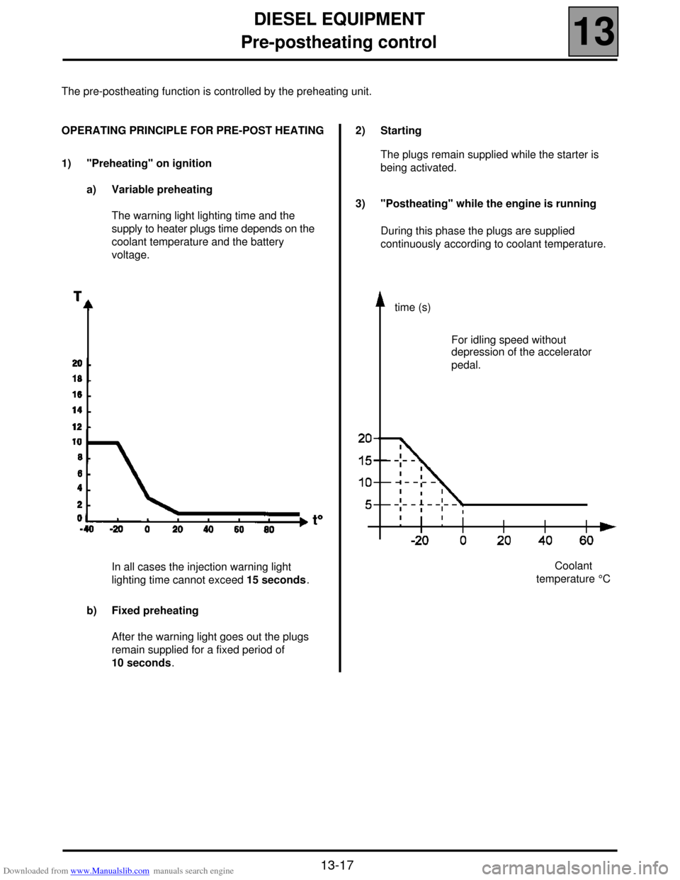
OPERATING PRINCIPLE FOR PRE-POST HEATING
1) "Preheating" on ignition
a) Variable preheating
The warning light lighting time and the
supply to heater plugs time depends on the
coolant temperature and the battery
voltage.
In all cases the injection warning light
lighting time cannot exceed 15 seconds.
b) Fixed preheating
After the warning light goes out the plugs
remain supplied for a fixed period of
10 seconds.2) Starting
The plugs remain supplied while the starter is
being activated.
3) "Postheating" while the engine is running
During this phase the plugs are supplied
continuously according to coolant temperature.
time (s)
Coolant
temperature °C For idling speed without
depression of the accelerator
pedal.
Page 69 of 118
Downloaded from www.Manualslib.com manuals search engine DIESEL EQUIPMENT
Heater plugs
13
13-18
Heater plugs
The resistance of a heater plug is 0.6 Ω.
Plugs may be removed without having to open the
high pressure circuit.
REMOVAL
Unclip the plug connector.
Clean the plug exterior to avoid any dirt entering the
cylinder.
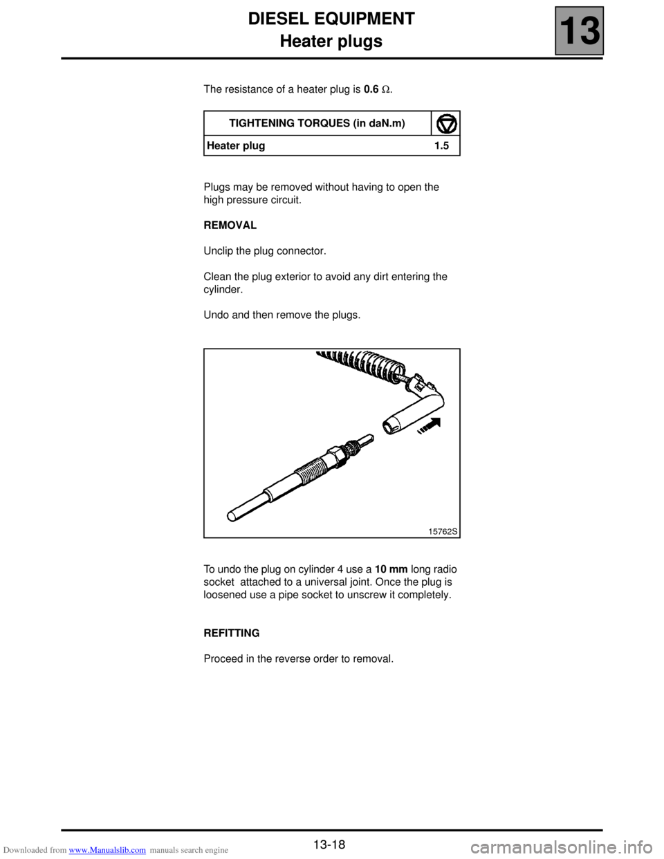
Undo and then remove the plugs.
To undo the plug on cylinder 4 use a 10 mm long radio
socket attached to a universal joint. Once the plug is
loosened use a pipe socket to unscrew it completely.
REFITTING
Proceed in the reverse order to removal.TIGHTENING TORQUES (in daN.m)
Heater plug 1.5
15762S
Page 70 of 118
Downloaded from www.Manualslib.com manuals search engine DIESEL EQUIPMENT
Thermal plunger
13
13-19
Thermal plunger
The three thermal plungers are located on a water unit
fixed under the manifold at the engine - gearbox joint.
The objective of the system is to reheat the coolant.
The thermal plungers are supplied with 12 volts by
two relays. One relay controls two thermal plungers,
and the other relay controls one thermal plunger. This
enables control of one, two or three thermal plungers
as required.
The resistance of the thermal plungers is:
0.45 ± 0.05 Ω at 20˚C. Control strategy
When the thermal plungers are operating the idling
speed is brought to 900 rpm.
Thermal plungers cannot operate in the case of:
– preheating,
– post heating,
– heated windscreen selected,
– engine speed below 700 rpm.,
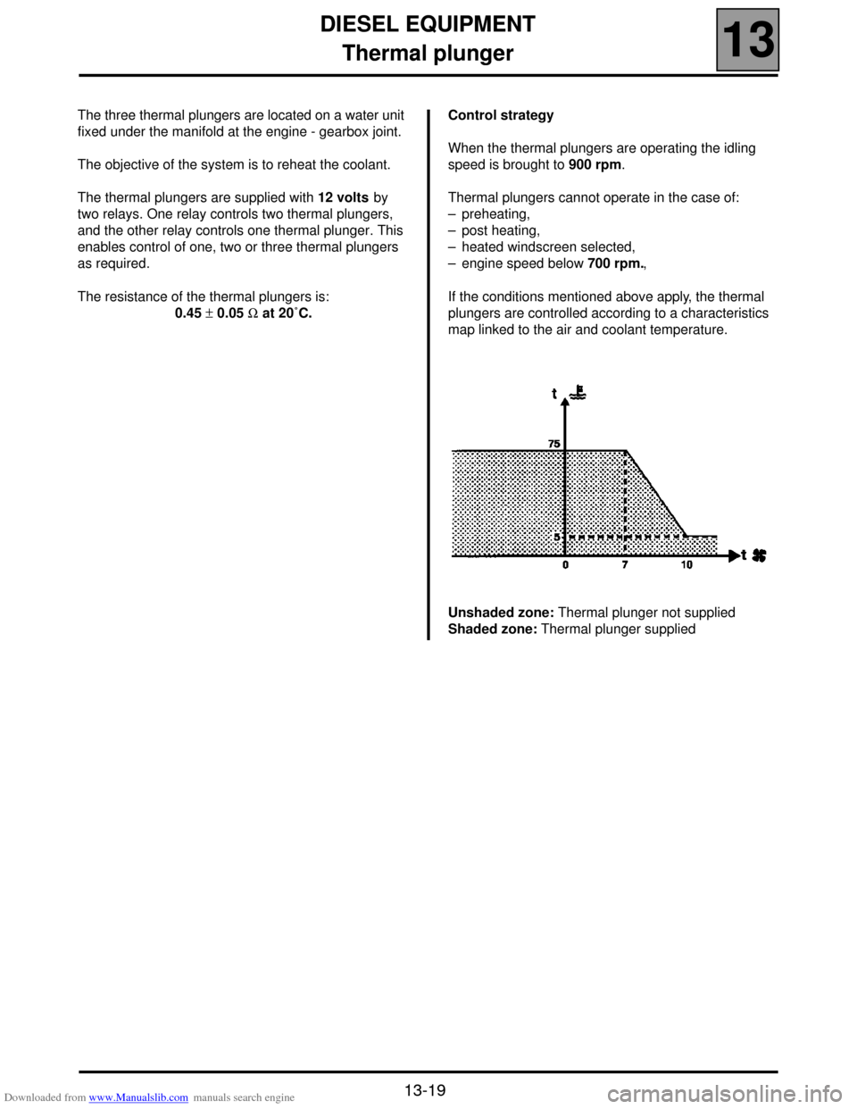
If the conditions mentioned above apply, the thermal
plungers are controlled according to a characteristics
map linked to the air and coolant temperature.
Unshaded zone: Thermal plunger not supplied
Shaded zone: Thermal plunger supplied