diagram RENAULT SCENIC 2008 J84 / 2.G Passenger Comparment Connection Unit Manual Online
[x] Cancel search | Manufacturer: RENAULT, Model Year: 2008, Model line: SCENIC, Model: RENAULT SCENIC 2008 J84 / 2.GPages: 391
Page 257 of 391
PASSENGER COMPARTMENT CONNECTION UNIT
Fault finding - Interpretation of commands87B
87B - 257
PASSENGER COMPARTMENT CONNECTION UNIT
Fault finding - Interpretation of commands87B
87B - 257V9 MR-372-J84-87B000$774.mif
UCH
Vdiag No.: 44, 48,
4C, 4D, 4F, 50
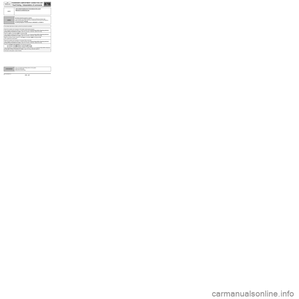
AC015
AIR-CONDITIONING BUTTON INDICATOR LIGHT
Manual air conditioning only
NOTESNo faults should be present or stored.
This command is for testing operation of the air-conditioning indicator light.
Apply the after ignition feed, and the air conditioning control panel should light up.
The command lasts 7 seconds.
Use Wiring Diagrams Technical Note for MEGANE II or SCENIC II.
The indicator light does not light up when the command is activated.
Check the condition and connection of the heater control panel connector.
If the connector is faulty and if there is a repair procedure (see Technical Note 6015A, Repairing electrical
wiring, Wiring: Precautions for repair), repair the connector; otherwise, replace the wiring.
Check for earth on connection NAM of component 316.
If the connector is faulty and if there is a repair procedure (see Technical Note 6015A, Repairing electrical
wiring, Wiring: Precautions for repair), repair the connector; otherwise, replace the wiring.
With the command running, check for + 12 V feed on connection 38ES of component 316.
If OK, replace the control panel.
Check the condition and connection of connector PE2 on the UCH
If the connector is faulty and if there is a repair procedure (see Technical Note 6015A, Repairing electrical
wiring, Wiring: Precautions for repair), repair the connector; otherwise, replace the wiring.
Check the insulation and continuity of the following connection:
●Connection code 38ES between components 645 and 319.
●Connection code NAM between component 319 and earth.
If the connection or connections are faulty and there is a repair procedure (see Technical Note 6015A, Electrical
wiring repair, Wiring: Precautions for repair), repair the wiring, otherwise replace it.
If the fault is still present, contact Techline.
AFTER REPAIRCarry out another fault finding check on the system.
Clear the stored faults.
Deal with any other faults.
Page 258 of 391
PASSENGER COMPARTMENT CONNECTION UNIT
Fault finding - Interpretation of commands87B
87B - 258
PASSENGER COMPARTMENT CONNECTION UNIT
Fault finding - Interpretation of commands87B
87B - 258V9 MR-372-J84-87B000$774.mif
UCH
Vdiag No.: 44, 48,
4C, 4D, 4F, 50
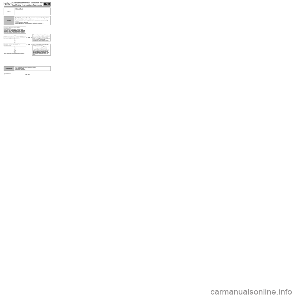
*RCH: Passenger Compartment Heating ResistorsAC016
RCH* 1 RELAY
NOTESCheck that the vehicle is fitted with passenger compartment heating resistors.
No faults should be present or stored.
This command is for testing the operation of the passenger compartment heating
resistors.
The command lasts 7 seconds.
Use Wiring Diagrams Technical Note for MEGANE II or SCENIC II.
Check for earth on connection NAM of
component 1113.
If the connector is faulty and if there is a repair
procedure (see Technical Note 6015A, Repairing
electrical wiring, Wiring: Precautions for repair),
repair the connector; otherwise, replace the wiring.
With the command running, check for + 12 V feed on
connection 38LL of component 1113.
NO
Check for + 12 V on connection BP9 of
component 1067.
NO
YESCheck that the resistances, between
connections 38LL and MAK (track 2) and
between connections 38LL and MAK
(track 4) of component 1113, are equal to
infinity. Replace the passenger
compartment heating resistors if faulty.
YESCheck the insulation and continuity of
the following connection:
●Connection code 38LL between
components 1067 and 1113.
If the connector is faulty and if there is a
repair procedure (see Technical Note
6015A, Repairing electrical wiring,
Wiring: Precautions for repair), repair
the connector; otherwise, replace the
wiring.
AFTER REPAIRCarry out another fault finding check on the system.
Clear the stored faults.
Deal with any other faults.
Page 261 of 391
PASSENGER COMPARTMENT CONNECTION UNIT
Fault finding - Interpretation of commands87B
87B - 261
PASSENGER COMPARTMENT CONNECTION UNIT
Fault finding - Interpretation of commands87B
87B - 261V9 MR-372-J84-87B000$774.mif
UCH
Vdiag No.: 44, 48,
4C, 4D, 4F, 50
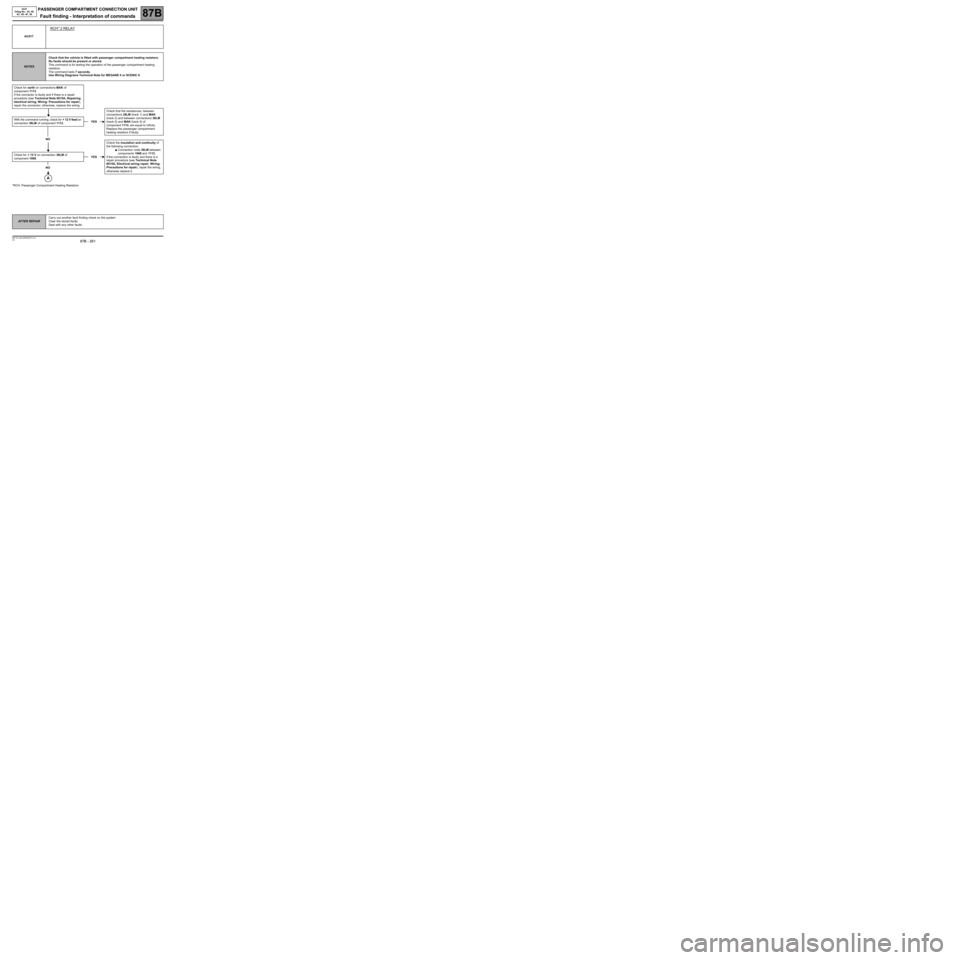
*RCH: Passenger Compartment Heating ResistorsAC017
RCH* 2 RELAY
NOTESCheck that the vehicle is fitted with passenger compartment heating resistors.
No faults should be present or stored.
This command is for testing the operation of the passenger compartment heating
resistors.
The command lasts 7 seconds.
Use Wiring Diagrams Technical Note for MEGANE II or SCENIC II.
Check for earth on connections MAK of
component 1113.
If the connector is faulty and if there is a repair
procedure (see Technical Note 6015A, Repairing
electrical wiring, Wiring: Precautions for repair),
repair the connector; otherwise, replace the wiring.
With the command running, check for + 12 V feed on
connection 38LM of component 1113.
NO
Check for + 12 V on connection 38LM of
component 1068.
NO
YESCheck that the resistances, between
connections 38LM (track 1) and MAK
(track 2) and between connections 38LM
(track 5) and MAK (track 4) of
component 1113, are equal to infinity.
Replace the passenger compartment
heating resistors if faulty.
YESCheck the insulation and continuity of
the following connection:
●Connection code 38LM between
components 1068 and 1113.
If the connection is faulty and there is a
repair procedure (see Technical Note
6015A, Electrical wiring repair, Wiring:
Precautions for repair), repair the wiring,
otherwise replace it.
AFTER REPAIRCarry out another fault finding check on the system.
Clear the stored faults.
Deal with any other faults.
Page 264 of 391
PASSENGER COMPARTMENT CONNECTION UNIT
Fault finding - Interpretation of commands87B
87B - 264
PASSENGER COMPARTMENT CONNECTION UNIT
Fault finding - Interpretation of commands87B
87B - 264V9 MR-372-J84-87B000$774.mif
UCH
Vdiag No.: 44, 48,
4C, 4D, 4F, 50
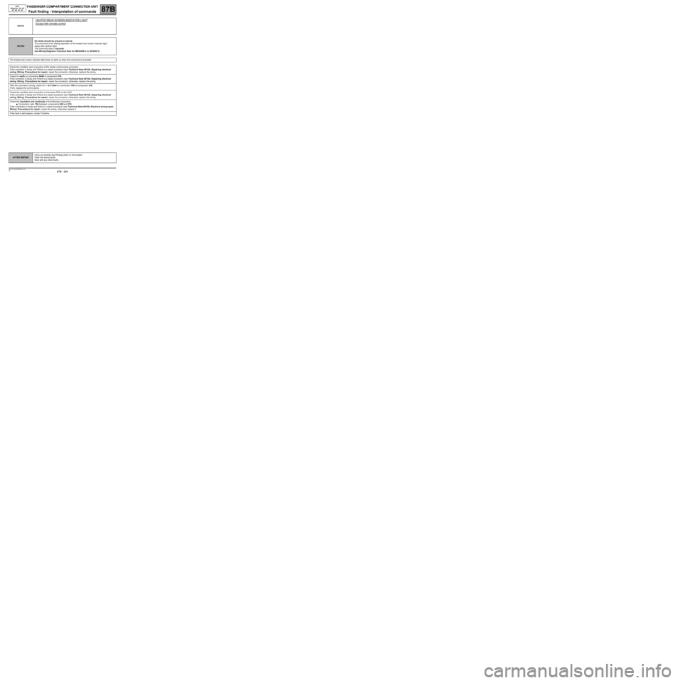
AC019
HEATED REAR SCREEN INDICATOR LIGHT
Except with climate control
NOTESNo faults should be present or stored.
This command is for testing operation of the heated rear screen indicator light.
Apply after ignition feed.
The command lasts 7 seconds.
Use Wiring Diagrams Technical Note for MEGANE II or SCENIC II.
The heated rear screen indicator light does not light up when the command is activated.
Check the condition and connection of the heater control panel connector.
If the connector is faulty and if there is a repair procedure (see Technical Note 6015A, Repairing electrical
wiring, Wiring: Precautions for repair), repair the connector; otherwise, replace the wiring.
Check for earth on connection NAM of component 319.
If the connector is faulty and if there is a repair procedure (see Technical Note 6015A, Repairing electrical
wiring, Wiring: Precautions for repair), repair the connector; otherwise, replace the wiring.
With the command running, check for + 12 V feed on connection 15A of component 316.
If OK, replace the control panel.
Check the condition and connection of connector PE2 on the UCH
If the connector is faulty and if there is a repair procedure (see Technical Note 6015A, Repairing electrical
wiring, Wiring: Precautions for repair), repair the connector; otherwise, replace the wiring.
Check the insulation and continuity of the following connection:
●Connection code 15A between components 645 and 319.
If the connection is faulty and there is a repair procedure (see Technical Note 6015A, Electrical wiring repair,
Wiring: Precautions for repair), repair the wiring, otherwise replace it.
If the fault is still present, contact Techline.
AFTER REPAIRCarry out another fault finding check on the system.
Clear the stored faults.
Deal with any other faults.
Page 265 of 391
PASSENGER COMPARTMENT CONNECTION UNIT
Fault finding - Interpretation of commands87B
87B - 265
PASSENGER COMPARTMENT CONNECTION UNIT
Fault finding - Interpretation of commands87B
87B - 265V9 MR-372-J84-87B000$774.mif
UCH
Vdiag No.: 44, 48,
4C, 4D, 4F, 50
*CPE: Electric central door lockingAC020
CPE* BUTTON INDICATOR
NOTESNo faults should be present or stored.
This command is used to check whether the button has a power supply.
The command lasts 7 seconds.
Use Wiring Diagrams Technical Note for MEGANE II or SCENIC II.
The central door locking button light does not light up when the command is performed.
Check the connection and condition of the central door locking button connector.
If the connector is faulty and if there is a repair procedure (see Technical Note 6015A, Repairing electrical
wiring, Wiring: Precautions for repair), repair the connector; otherwise, replace the wiring.
Check for an earth on connection MAM of component 1391.
If the connector is faulty and if there is a repair procedure (see Technical Note 6015A, Repairing electrical
wiring, Wiring: Precautions for repair), repair the connector; otherwise, replace the wiring.
With the command running, check for + 12 V feed on connection 20M of component 1391.
If OK, replace the button.
Check the condition and connection of connector PE1 on the UCH.
If the connector is faulty and if there is a repair procedure (see Technical Note 6015A, Repairing electrical
wiring, Wiring: Precautions for repair), repair the connector; otherwise, replace the wiring.
Check the insulation and continuity of the following connections:
●Connection code 20M.
●Connection code 20AW between components 645 and 1391.
If the connection or connections are faulty and there is a repair procedure (see Technical Note 6015A, Electrical
wiring repair, Wiring: Precautions for repair), repair the wiring, otherwise replace it.
If the fault is still present, contact Techline.
AFTER REPAIRCarry out another fault finding check on the system.
Clear the stored faults.
Deal with any other faults.
Page 266 of 391
PASSENGER COMPARTMENT CONNECTION UNIT
Fault finding - Interpretation of commands87B
87B - 266
PASSENGER COMPARTMENT CONNECTION UNIT
Fault finding - Interpretation of commands87B
87B - 266V9 MR-372-J84-87B000$774.mif
UCH
Vdiag No.: 44, 48,
4C, 4D, 4F, 50
AC021
INTERIOR LIGHTS
NOTESNo faults should be present or stored.
This command is for testing interior lights operation.
Check the bulbs.
Use Wiring Diagrams Technical Note for MEGANE II or SCENIC II.
The interior lights do not light when the command is activated.
Check the condition and connection of the interior lights connectors.
If the connector is faulty and if there is a repair procedure (see Technical Note 6015A, Repairing electrical
wiring, Wiring: Precautions for repair), repair the connector; otherwise, replace the wiring.
Check for earth on connection MAM of components 213 and 300.
If the connector is faulty and if there is a repair procedure (see Technical Note 6015A, Repairing electrical
wiring, Wiring: Precautions for repair), repair the connector; otherwise, replace the wiring.
With the command running, check for + 12 V feed on connection BPT of components 213 and 300.
If OK, check the bulbs again, and if still not OK replace the interior light(s).
Check the condition and connection of the PP3 connector on the UCH.
If the connector is faulty and if there is a repair procedure (see Technical Note 6015A, Repairing electrical
wiring, Wiring: Precautions for repair), repair the connector; otherwise, replace the wiring.
Check the insulation and continuity of the following connection:
●Connection code 13E.
Between components 645 and 213.
Between components 645 and 300.
If the connection or connections are faulty and there is a repair procedure (see Technical Note 6015A, Electrical
wiring repair, Wiring: Precautions for repair), repair the wiring, otherwise replace it.
If the fault is still present, contact the Techline.
AFTER REPAIRCarry out another fault finding check on the system.
Clear the stored faults.
Deal with any other faults.
Page 267 of 391
PASSENGER COMPARTMENT CONNECTION UNIT
Fault finding - Interpretation of commands87B
87B - 267
PASSENGER COMPARTMENT CONNECTION UNIT
Fault finding - Interpretation of commands87B
87B - 267V9 MR-372-J84-87B000$774.mif
UCH
Vdiag No.: 44, 48,
4C, 4D, 4F, 50
AC022
Left-hand direction indicator
NOTESNo faults should be present or stored.
This command is for testing direction indicator operation.
Apply after ignition feed.
Check the bulbs.
Use Wiring Diagrams Technical Note for MEGANE II or SCENIC II.
The direction indicators do not light when the command is activated.
Check the condition and connection of the connectors for the left-hand headlight, the left-hand repeater and the
rear left-hand light.
If the connector is faulty and if there is a repair procedure (see Technical Note 6015A, Repairing electrical
wiring, Wiring: Precautions for repair), repair the connector; otherwise, replace the wiring.
Check for earth on the following connections:
●Connection code MAS.
Between component 227 and earth.
Between component 268 and earth.
●Connection code MZ between component 173 and earth.
If the connection or connections are faulty and there is a repair procedure (see Technical Note 6015A, Electrical
wiring repair, Wiring: Precautions for repair), repair the wiring, otherwise replace it.
Check for the + 12 V feed with the command running on the following connections:
●Connection code 64C.
Between component 227 and earth.
Between component 173 and earth.
●Connection code 64V between component 268 and earth.
If the connection or connections are faulty and there is a repair procedure (see Technical Note 6015A, Electrical
wiring repair, Wiring: Precautions for repair), repair the wiring, otherwise replace it.
If the + 12 V feed is correct, check the bulbs again and if the bulbs still do not work, replace the rear light(s).
Check the condition and connection of the PP3 connector on the UCH.
If the connector is faulty and if there is a repair procedure (see Technical Note 6015A, Repairing electrical
wiring, Wiring: Precautions for repair), repair the connector; otherwise, replace the wiring.
AFTER REPAIRCarry out another fault finding check on the system.
Clear the stored faults.
Deal with any other faults.
Page 269 of 391
PASSENGER COMPARTMENT CONNECTION UNIT
Fault finding - Interpretation of commands87B
87B - 269
PASSENGER COMPARTMENT CONNECTION UNIT
Fault finding - Interpretation of commands87B
87B - 269V9 MR-372-J84-87B000$774.mif
UCH
Vdiag No.: 44, 48,
4C, 4D, 4F, 50
AC023
RIGHT-HAND DIRECTION INDICATOR
NOTESNo faults should be present or stored.
This command is for testing direction indicator operation.
Apply after ignition feed.
Check the bulbs.
Use Wiring Diagrams Technical Note for MEGANE II or SCENIC II.
The direction indicators do not light when the command is activated.
Check the condition and connection of the connectors for the right-hand headlight, the right-hand repeater and the
rear right-hand light.
If the connector is faulty and if there is a repair procedure (see Technical Note 6015A, Repairing electrical
wiring, Wiring: Precautions for repair), repair the connector; otherwise, replace the wiring.
Check for earth on the following connections:
●Connection code MAS.
Between component 226 and earth.
Between component 267 and earth.
●Connection code MAQ between component 172 and earth.
If the connection or connections are faulty and there is a repair procedure (see Technical Note 6015A, Electrical
wiring repair, Wiring: Precautions for repair), repair the wiring, otherwise replace it.
Check for the + 12 V feed with the command running on the following connections:
●Connection code 64D.
Between component 226 and earth.
Between component 172 and earth.
●Connection code 64U between component 267 and earth.
If the connection or connections are faulty and there is a repair procedure (see Technical Note 6015A, Electrical
wiring repair, Wiring: Precautions for repair), repair the wiring, otherwise replace it.
If the + 12 V feed is correct, check the bulbs again and if the bulbs still do not work, replace the rear light(s).
Check the condition and connection of the PP3 connector on the UCH.
If the connector is faulty and if there is a repair procedure (see Technical Note 6015A, Repairing electrical
wiring, Wiring: Precautions for repair), repair the connector; otherwise, replace the wiring.
AFTER REPAIRCarry out another fault finding check on the system.
Clear the stored faults.
Deal with any other faults.
Page 271 of 391
PASSENGER COMPARTMENT CONNECTION UNIT
Fault finding - Interpretation of commands87B
87B - 271
PASSENGER COMPARTMENT CONNECTION UNIT
Fault finding - Interpretation of commands87B
87B - 271V9 MR-372-J84-87B000$774.mif
UCH
Vdiag No.: 44, 48,
4C, 4D, 4F, 50
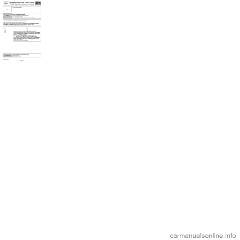
AC024
CARD READER LIGHT
NOTESNo faults should be present or stored.
This command is for testing card reader operation.
The command lasts 7 seconds.
Use Wiring Diagrams Technical Note for MEGANE II or SCENIC II.
The card reader light does not light up when the command is activated.
Check the condition and connection of the card reader connector.
If the connector is faulty and if there is a repair procedure (see Technical Note 6015A, Repairing electrical
wiring, Wiring: Precautions for repair), repair the connector; otherwise, replace the wiring.
Check for earth on connection NAM of component 1088.
If OK: If faulty:
Check the condition and connection of connector PE2 on the UCH
If the connector is faulty and if there is a repair procedure (see Technical Note
6015A, Repairing electrical wiring, Wiring: Precautions for repair), repair the
connector; otherwise, replace the wiring.
Check the insulation and continuity of the following connection:
●Connection code 26BK between components 645 and 1082.
If the connection is faulty and there is a repair procedure (see Technical Note
6015A, Electrical wiring repair, Wiring: Precautions for repair), repair the
wiring, otherwise replace it.
If the fault is still present, contact Techline.
AFTER REPAIRCarry out another fault finding check on the system.
Clear the stored faults.
Deal with any other faults.
Page 274 of 391
PASSENGER COMPARTMENT CONNECTION UNIT
Fault finding - Interpretation of commands87B
87B - 274
PASSENGER COMPARTMENT CONNECTION UNIT
Fault finding - Interpretation of commands87B
87B - 274V9 MR-372-J84-87B000$774.mif
UCH
Vdiag No.: 44, 48,
4C, 4D, 4F, 50
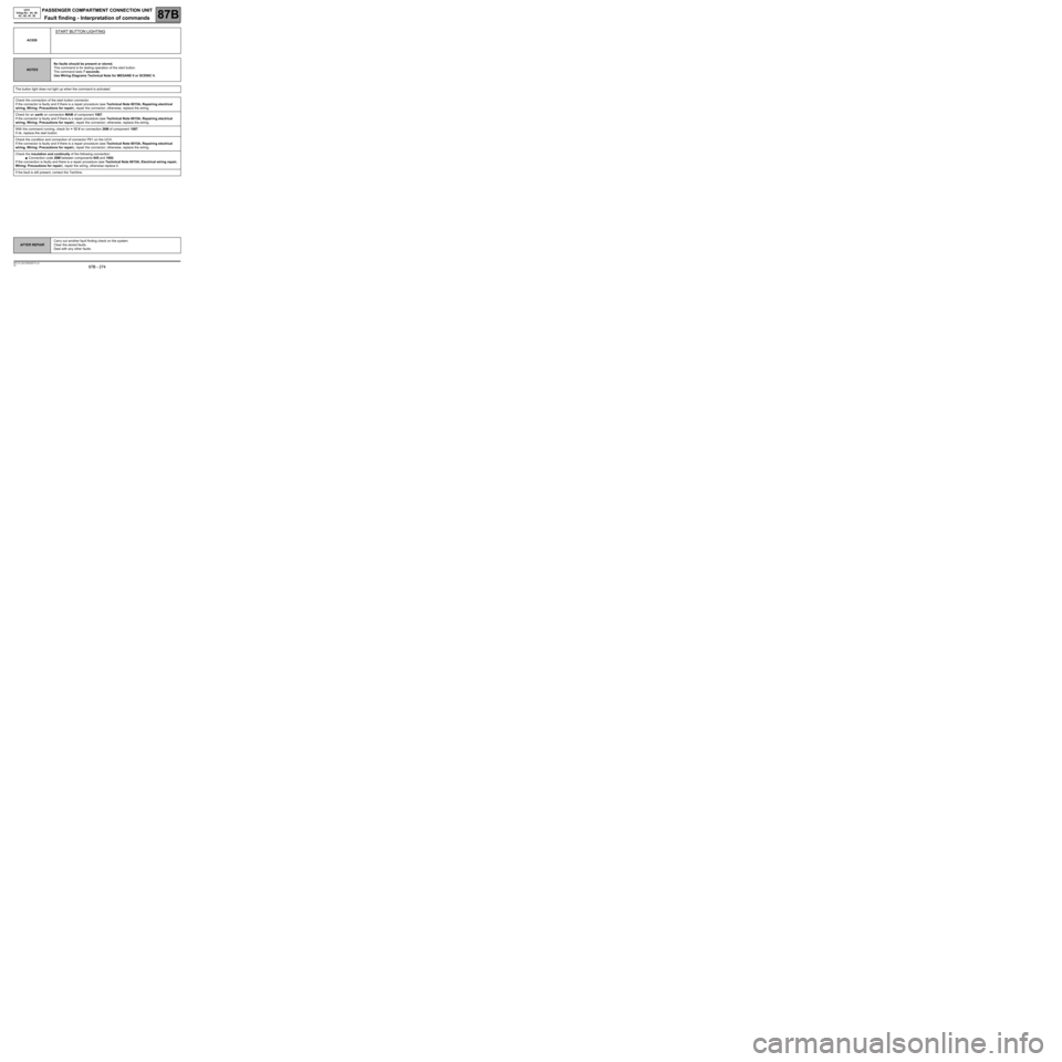
AC026
START BUTTON LIGHTING
NOTESNo faults should be present or stored.
This command is for testing operation of the start button.
The command lasts 7 seconds.
Use Wiring Diagrams Technical Note for MEGANE II or SCENIC II.
The button light does not light up when the command is activated.
Check the connection of the start button connector.
If the connector is faulty and if there is a repair procedure (see Technical Note 6015A, Repairing electrical
wiring, Wiring: Precautions for repair), repair the connector; otherwise, replace the wiring.
Check for an earth on connection MAM of component 1087.
If the connector is faulty and if there is a repair procedure (see Technical Note 6015A, Repairing electrical
wiring, Wiring: Precautions for repair), repair the connector; otherwise, replace the wiring.
With the command running, check for + 12 V on connection 26M of component 1087.
If ok, replace the start button.
Check the condition and connection of connector PE1 on the UCH.
If the connector is faulty and if there is a repair procedure (see Technical Note 6015A, Repairing electrical
wiring, Wiring: Precautions for repair), repair the connector; otherwise, replace the wiring.
Check the insulation and continuity of the following connection:
●Connection code 26M between components 645 and 1082.
If the connection is faulty and there is a repair procedure (see Technical Note 6015A, Electrical wiring repair,
Wiring: Precautions for repair), repair the wiring, otherwise replace it.
If the fault is still present, contact the Techline.
AFTER REPAIRCarry out another fault finding check on the system.
Clear the stored faults.
Deal with any other faults.