torque SSANGYONG KORANDO 1997 Service Repair Manual
[x] Cancel search | Manufacturer: SSANGYONG, Model Year: 1997, Model line: KORANDO, Model: SSANGYONG KORANDO 1997Pages: 2053, PDF Size: 88.33 MB
Page 1450 of 2053

SSANGYONG MY2002
6A-8 POWER STEERING SYSTEM
KAA6A080
6. Remove the return line support clip from the front
frame.
Installation Notice
Tightening Torque 9 Nm (80 lb-in)
After installing the power steering fluid reservoir,
bleed the power steering system. Refer to
“Bleeding the Power Steering System” in this
section.
7. Installation should follow the removal procedure
in the reverse order.
Page 1455 of 2053

SSANGYONG MY2002
6A-4 POWER STEERING SYSTEM
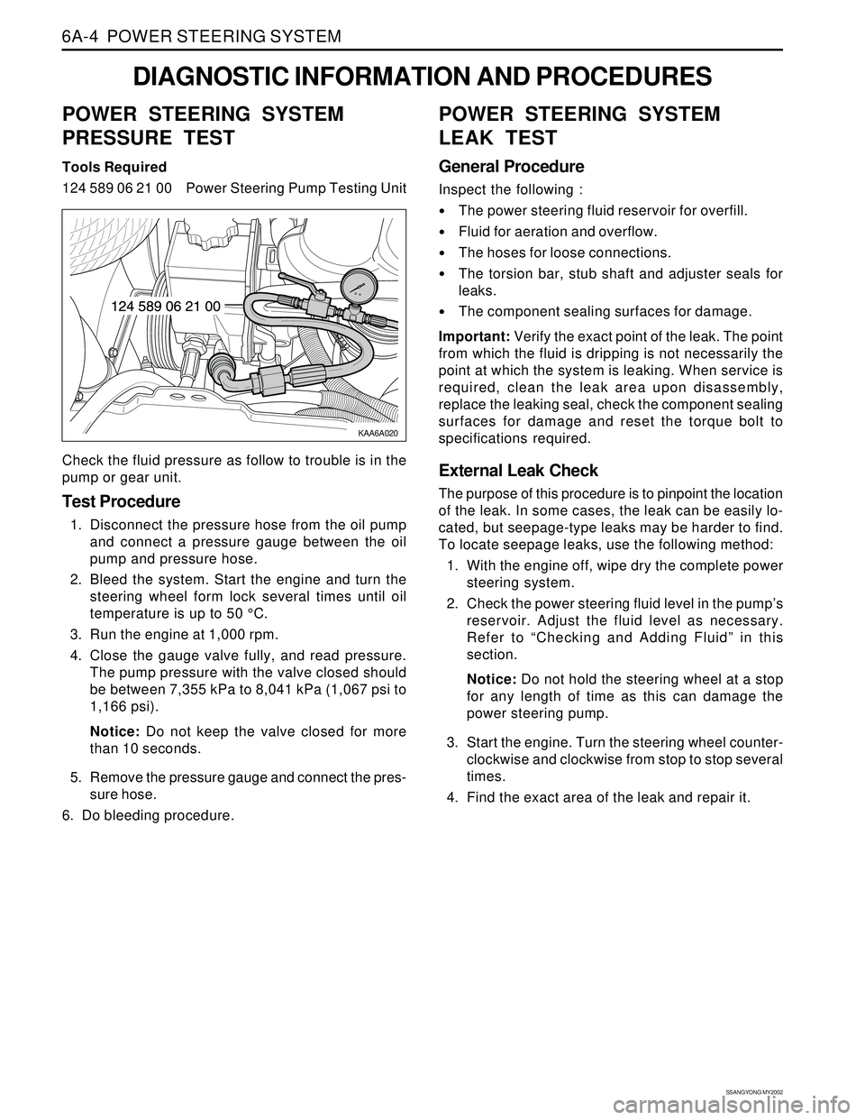
KAA6A020
DIAGNOSTIC INFORMATION AND PROCEDURES
POWER STEERING SYSTEM
PRESSURE TEST
Tools Required
124 589 06 21 00 Power Steering Pump Testing Unit
Check the fluid pressure as follow to trouble is in the
pump or gear unit.
Test Procedure
1. Disconnect the pressure hose from the oil pump
and connect a pressure gauge between the oil
pump and pressure hose.
2. Bleed the system. Start the engine and turn the
steering wheel form lock several times until oil
temperature is up to 50 °C.
3. Run the engine at 1,000 rpm.
4. Close the gauge valve fully, and read pressure.
The pump pressure with the valve closed should
be between 7,355 kPa to 8,041 kPa (1,067 psi to
1,166 psi).
Notice: Do not keep the valve closed for more
than 10 seconds.
5. Remove the pressure gauge and connect the pres-
sure hose.
6. Do bleeding procedure.
POWER STEERING SYSTEM
LEAK TEST
General Procedure
Inspect the following :
The power steering fluid reservoir for overfill.
Fluid for aeration and overflow.
The hoses for loose connections.
The torsion bar, stub shaft and adjuster seals for
leaks.
The component sealing surfaces for damage.
Important: Verify the exact point of the leak. The point
from which the fluid is dripping is not necessarily the
point at which the system is leaking. When service is
required, clean the leak area upon disassembly,
replace the leaking seal, check the component sealing
surfaces for damage and reset the torque bolt to
specifications required.
External Leak Check
The purpose of this procedure is to pinpoint the location
of the leak. In some cases, the leak can be easily lo-
cated, but seepage-type leaks may be harder to find.
To locate seepage leaks, use the following method:
1. With the engine off, wipe dry the complete power
steering system.
2. Check the power steering fluid level in the pump’s
reservoir. Adjust the fluid level as necessary.
Refer to “Checking and Adding Fluid” in this
section.
Notice: Do not hold the steering wheel at a stop
for any length of time as this can damage the
power steering pump.
3. Start the engine. Turn the steering wheel counter-
clockwise and clockwise from stop to stop several
times.
4. Find the exact area of the leak and repair it.
Page 1457 of 2053

SSANGYONG MY2002
6A-6 POWER STEERING SYSTEM
KAA6A040
3. Remove the power steering fluid reservoir
mounting bolts (1).
Removal Notice:
One power steering fluid reservoir mounting bolt
(2) is located in the fluid reservoir.
Installation Notice
KAA6A030
ON-VEHICLE SERVICE
POWER STEERING FLUID
RESERVOIR
Tools Required
DW310-021Power Steering Pump Pulley Remover/
Installer
Removal and Installation Procedure
1. Remove the power steering pump. Refer to
Section 6B, Power Steering Pump.
2. Remove the power steering pump pulley nut, using
the power steering pump pulley remover/installer
DW310-021.
Installation Notice
REPAIR INSTRUCTIONS
Tightening Torque 61 Nm (44 lb-ft)
15 Nm (11 lb-ft)
18 Nm (13 lb-ft)
Tightening
TorqueBolts (1)
Bolt (2)
4. Remove the power steering fluid reservoir upward.
After installing the power steering fluid reservoir,
bleed the power steering system. Refer to
“Bleeding the Power Steering System” in this
section.
5. Installation should follow the removal procedure
in the reverse order.
Page 1458 of 2053

POWER STEERING SYSTEM 6A-7
SSANGYONG MY2002
KAA6A050
KAA6A060
4. Disconnect the return line pipe from the power
steering gear outlet.
Installation Notice
KAA6A070
5. Disconnect the pressure line pipe from the power
steering gear inlet.
Installation Notice
POWER STEERING PUMP HOSES
AND PIPES
Removal and Installation Procedure
1. Remove the battery. Refer to Section 1E, Engine
Electrical.
2. Siphon the power steering fluid from the fluid reser-
voir.
3. Disconnect the pressure line pipe from the outlet
connection on the power steering pump and return
hose from the inlet connection on the power
steering fluid reservoir.
Installation Notice
Tightening Torque 44 Nm (33 lb-ft)
Tightening Torque 17 Nm (13 lb-ft)
Tightening Torque 17 Nm (13 lb-ft)
Page 1459 of 2053

SSANGYONG MY2002
6A-8 POWER STEERING SYSTEM
KAA6A080
6. Remove the return line support clip from the front
frame.
Installation Notice
Tightening Torque 9 Nm (80 lb-in)
After installing the power steering fluid reservoir,
bleed the power steering system. Refer to
“Bleeding the Power Steering System” in this
section.
7. Installation should follow the removal procedure
in the reverse order.
Page 1466 of 2053

POWER STEERING PUMP 6B-5
SSANGYONG MY2002
KAA6B050
5. Remove the power steering pump assembly
mounting bolts.
Installation Notice
KAA6B040
3. Siphon the power steering fluid from the fluid reser-
voir.
4. Disconnect the pressure line pipe from the outlet
connectionon the power steering pump and return
hose from the inlet connection on the power
steering fluid reservoir.
Installation Notice
Tightening Torque 44 Nm (33 lb-ft)
KAA6B010
POWER STEERING PUMP
ASSEMBLY
Removal and Installation Procedure
1. Remove the battery. Refer to Section 1E, Engine
Electrical.
2. Use a wrench to turn the tensioner bolt clockwise,
compressing the tensioner, and releasing the
tension on the serpentine accessory drive belt.
Loosen the serpentine accessory drive belt.
Tightening Torque 25 Nm (17 lb-ft)
6. Remove the power steering pump assembly.
Page 1467 of 2053

SSANGYONG MY2002
6B-6 POWER STEERING PUMP
KAA6B060
KAA6B070
3. Remove the power steering fluid reservoir
mounting bolts (1).
Remove Notice:
One power steering fluid reservoir mounting bolt
(2) is located in the fluid reservoir.
Installation Notice
KAA6B080
5. Remove the power steering pump mounting
bracket bolts.
Installation Notice
UNIT REPAIR
PUMP
Tools Required
DW310-021Power Steering Pump Pulley Remover/
Installer
Disassembly and Assembly Procedure
Important: The power steering pump in this vehicle is
not serviceable. Replace, do not repair, a faulty power
steering pump. Refer to “Power Steering Pump
Diagnosis” in this section.
1. Remove the power steering pump assembly. Refer
to “Power Steering Pump Assembly” in this
section.
2. Remove the power steering pump pulley nut, using
the power steering pump pulley remover/installer
DW 310-021.
Tightening Torque 16 Nm (12 lb-ft)15 Nm (11 lb-ft)
18 Nm (13 lb-ft)
Tightening
TorqueBolts (1)
Bolt (2)
4. Remover the power steering fluid reservoir
upward.
6. Installation should follow the removal procedure
in the reverse order.
Page 1476 of 2053

SSANGYONG MY2002
6C-8 POWER STEERING GEAR
KAA6C040
KAA6C030
ON-VEHICLE SERVICE
RACK AND PINION ASSEMBLY
Tools Required
661 589 13 33 00 Ball Joint Remover
Removal and Installation Procedure
1. Raise and suitably support the vehicle.
2. Remove the wheels. Refer to Section 2E, Tires
and Wheels.
3. Remove the intermediate shaft. Refer to
“Intermediate shaft” in this section.
4. Disconnect the return line pipe from the power
steering gear outlet. Place a drain pan under the
steering gear to catch the power steering fluid.
Installation Notice
REPAIR INSTRUCTIONS
Tightening Torque 17 Nm (13 lb-ft)
5. Disconnect the pressure line pipe from the power
steering gear inlet.
Installation Notice
Tightening Torque 17 Nm (13 lb-ft)
Page 1477 of 2053

POWER STEERING GEAR 6C-9
SSANGYONG MY2002
KAA6C140
KAA6C050
KAA6C050
6. Remove the outer tie rod nuts and disconnect the
tie rod ends from the knuckle using the ball joint
remover 661 589 13 33 00.
Installation Notice
7. Remove the rack and pinion assembly mounting
bolts and remove therackand pinion assembly.
Installation Notice
Tightening Torque 40 Nm (30 lb-ft)
After installing the rack and pinion assembly,
bleed the power steering system. Refer to
Section 6A, Power Steering System.
OUTER TIE ROD
Tools Required
661589 13 33 00 BallJointRemover
Removal and Installation Procedure
1. Remove the wheel. Refer to Section 2E, Tires and
wheels.
2. Mark the threads on the inner tie rod to aid in
repositioning the adjusting nut.
3. Remove the outer tie rod nut and disconnect the
outer tie rod from the knuckle using the ball joint
remover 661 589 13 33 00.
Installation Notice
Tightening Torque 78 Nm (58 lb-ft)
Tightening Torque 40 Nm (30 lb-ft)
Page 1479 of 2053

POWER STEERING GEAR 6C-11
SSANGYONG MY2002
KAA6C120
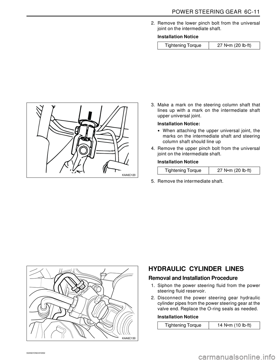
KAA6C130
2. Remove the lower pinch bolt from the universal
joint on the intermediate shaft.
Installation Notice
Tightening Torque 27 Nm (20 lb-ft)
3. Make a mark on the steering column shaft that
lines up with a mark on the intermediate shaft
upper universal joint.
Installation Notice:
When attaching the upper universal joint, the
marks on the intermediate shaft and steering
column shaft should line up
4. Remove the upper pinch bolt from the universal
joint on the intermediate shaft.
Installation Notice
5. Remove the intermediate shaft.
Tightening Torque 27 Nm (20 lb-ft)
HYDRAULIC CYLINDER LINES
Removal and Installation Procedure
1. Siphon the power steering fluid from the power
steering fluid reservoir.
2. Disconnect the power steering gear hydraulic
cylinder pipes from the power steering gear at the
valve end. Replace the O-ring seals as needed.
Installation Notice
Tightening Torque 14 Nm (10 lb-ft)