torque SSANGYONG KORANDO 1997 Service Repair Manual
[x] Cancel search | Manufacturer: SSANGYONG, Model Year: 1997, Model line: KORANDO, Model: SSANGYONG KORANDO 1997Pages: 2053, PDF Size: 88.33 MB
Page 1388 of 2053

SSANGYONG MY2002
5D1-66 TRANSFER CASE
KAA5D240
KAA5D250
ON-VEHICLE SERVICE
OIL REPLACEMENT
Important: Use only recommended oil or not the trans-
fer case will be severely damaged. Inspect every
10,000 km and replace every 60,000 km.
Specified Oil Level
The oil level should be just under the filler hole.
REPAIR INSTRUCTIONS
Oil Replacement
1. Lift the vehicle and make sure safety.
2. Prepare a vessel to drain transfer case oil.
3. Remove the planner damper, if equipped.
4. Remove the drain plug and filler plug, and drain
the oil completely.
5. Install and tighten the drain plug.
Installation Notice
6. Replenish recommended transfer case oil to speci-
fied oil level through the filler plughole.
7. Install and tighten the filler plug.
Installation Notice
8. Check oil leakage.
9. Install the planner damper.
Installation Notice
Tightening Torque19 - 30 Nm
(14 - 22 lb-ft)
Tightening Torque4 - 6 Nm
(35 - 53 lb-in)
Tightening Torque29 - 41 Nm
(21 - 30 lb-ft)
Page 1389 of 2053
TRANSFER CASE 5D1-67
SSANGYONG MY2002
KAA5D260
KAA5D270
TRANSFER CASE CONTROL UNIT
(TCCU)
Removal and Installation Procedure
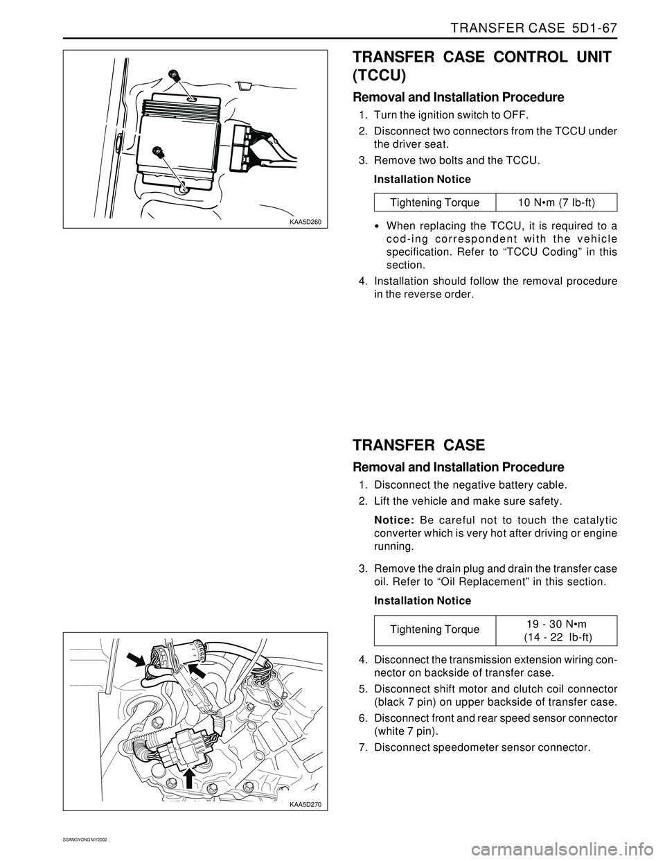
1. Turn the ignition switch to OFF.
2. Disconnect two connectors from the TCCU under
the driver seat.
3. Remove two bolts and the TCCU.
Installation Notice
Tightening Torque 10 Nm (7 lb-ft)
When replacing the TCCU, it is required to a
cod-ing correspondent with the vehicle
specification. Refer to “TCCU Coding” in this
section.
4. Installation should follow the removal procedure
in the reverse order.
TRANSFER CASE
Removal and Installation Procedure
1. Disconnect the negative battery cable.
2. Lift the vehicle and make sure safety.
Notice: Be careful not to touch the catalytic
converter which is very hot after driving or engine
running.
3. Remove the drain plug and drain the transfer case
oil. Refer to “Oil Replacement” in this section.
Installation Notice
4. Disconnect the transmission extension wiring con-
nector on backside of transfer case.
5. Disconnect shift motor and clutch coil connector
(black 7 pin) on upper backside of transfer case.
6. Disconnect front and rear speed sensor connector
(white 7 pin).
7. Disconnect speedometer sensor connector.
Tightening Torque19 - 30 Nm
(14 - 22 lb-ft)
Page 1390 of 2053
SSANGYONG MY2002
5D1-68 TRANSFER CASE
KAA5D280
KAA5D290
KAA5D300
KAA5D310
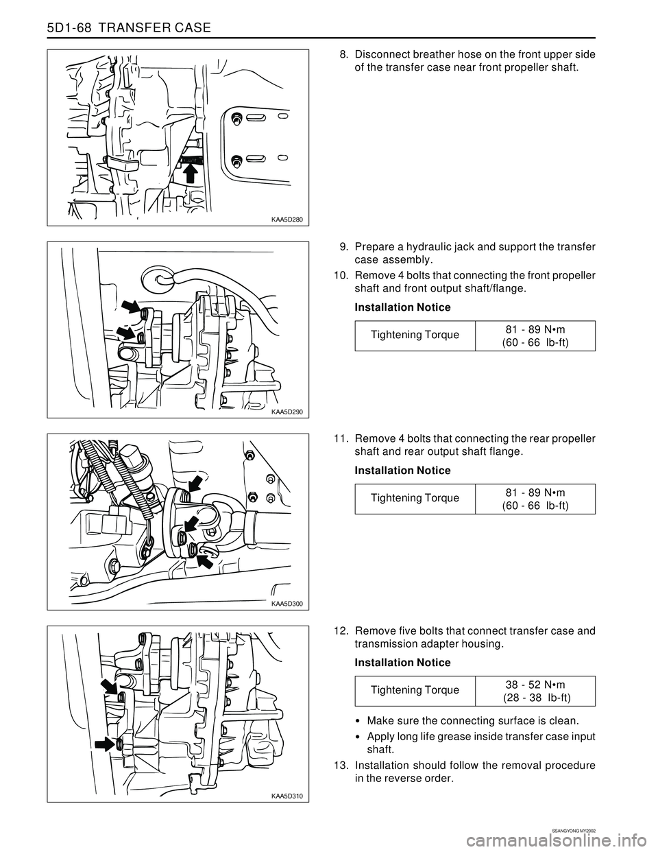
8. Disconnect breather hose on the front upper side
of the transfer case near front propeller shaft.
12. Remove five bolts that connect transfer case and
transmission adapter housing.
Installation Notice 11. Remove 4 bolts that connecting the rear propeller
shaft and rear output shaft flange.
Installation Notice 9. Prepare a hydraulic jack and support the transfer
case assembly.
10. Remove 4 bolts that connecting the front propeller
shaft and front output shaft/flange.
Installation Notice
Make sure the connecting surface is clean.
Apply long life grease inside transfer case input
shaft.
13. Installation should follow the removal procedure
in the reverse order.
Tightening Torque81 - 89 Nm
(60 - 66 lb-ft)
Tightening Torque81 - 89 Nm
(60 - 66 lb-ft)
Tightening Torque38 - 52 Nm
(28 - 38 lb-ft)
Page 1391 of 2053

TRANSFER CASE 5D1-69
SSANGYONG MY2002
KAA5D320
KAA5D330
SHIFT MOTOR
Removal and Installation Procedure
1. Disconnect the negative battery cable.
2. Disconnect shift motor and clutch coil connector
(black 7 pin) on upper backside of transfer case.
3. Remove three shift motor mounting bolts.
Installation Notice
6. Keeps the shift motor even and pull out carefully.
Notice: When removing shift motor, pay attention
to the location of triangular slot and shaft in
transfer case inside motor and mark the position.
7. Installation should follow the removal procedure
in the reverse order.
Installation Notice:
Clean the connection surface between transfer
case and shift motor.
Apply black non-acid cure silicone rubber or
equivalent to the surface.
Do not disassemble the shift motor and replace
with new one, if necessary.
Make sure the motor position to match with 4H/
4L switch selection. 4. Remove one shift motor bracket bolt.
Installation Notice
5. Loose two adjusting bolts on the shift motor if
neces-sary.
Installation Notice
Tightening Torque8 - 11 Nm
(70 - 97 lb-in)
Tightening Torque8 - 11 Nm
(70 - 97 lb-in)
Tightening Torque3 - 5 Nm
(27 - 44 lb-in)
Page 1392 of 2053

SSANGYONG MY2002
5D1-70 TRANSFER CASE
KAA5D340
KAA5D350
FRONT AND REAR PROPELLER
SHAFT SPEED SENSOR
Removal and Installation Procedure
1. Disconnect negative battery cable.
2. Disconnect front and rear speed sensor connector
(white 7 pin).
3. Remove shift motor. Refer to “Shift Motor” in this
sec-tion.
4. Remove front and rear propeller shaft speed
sensor retaining bolts.
Installation Notice
6. Disassemble the connector of front and rear
propeller shaft speed sensor.
7. Replace front or rear propeller shaft speed sensor,
as necessary.
Notice:
While replacing the speed sensor, make sure
the proper pin position.
Do not remove one wire to clutch coil in the
transfer case.
Make tidy on the wiring harness including
conduct tube.
8. Installation should follow the removal procedure
in the reverse order. 5. Remove the speed sensors by lifting up using
a tool such as flat screw drive.
Notice: Do not shock the speed sensor because
it is too sensitive at shock.
Tightening Torque3 - 6 Nm
(27 - 53 lb-in)
Page 1399 of 2053

TRANSFER CASE 5D1-77
SSANGYONG MY2002
KAA5D420
KAA5D590
23. Install the clutch coil and tighten three bolts.
Installation Notice
Caution: Do not kink or trap the wire while
seating the clutch coil to the case.
24. Install the pin on the tang end of the helical cam
into the hole in the front case.
25. Position the torsion spring tangs so that they are
pointing toward the top side of the transfer case
and just touching the high-low shift fork.
Caution: Do not bend the helical cam during
installation to the front case because of possible
damage to the pin at the tang end of the motor
shaft.
26. Install the shift rail through the high-low shift fork
and make sure that the reverse gear shift rail is
seated in the front case bore.
27. Install rear propeller shaft speed sensor toothed
wheel, vehicle speedometer gear and rear output
shaft seal if removed. Use oil seal installer or equiv-
alent.
Tightening Torque8 - 11 Nm
(6 - 8 lb-ft)
Page 1400 of 2053
SSANGYONG MY2002
5D1-78 TRANSFER CASE
31. Install the rear output shaft flange on rear output
shaft. Install the rubber seal, output shaft yoke
washer and nut. Tighten the nut and calk the nut
on the flat area.
Installation Notice
32. Install the shift motor. Refer to the “Shift Motor”
in this section.
33. Insert the brown wire and pin to speed sensor con-
nect and assemble the connector. Refer to “Front
and Rear Propeller Shaft Speed Sensors” in this
section.
34. Install the drain plug and tighten the drain plug.
Installation Notice
35. Fill the transfer case with 1.4 liters of ATF or equiva
lent.
Notice: Fluid level should be just below the filler
plug-hole.
36. Install the filler plug and tighten.
Installation Notice
37. Install the transfer case to the vehicle. Refer to
“Transfer Case” in the section.
5D380
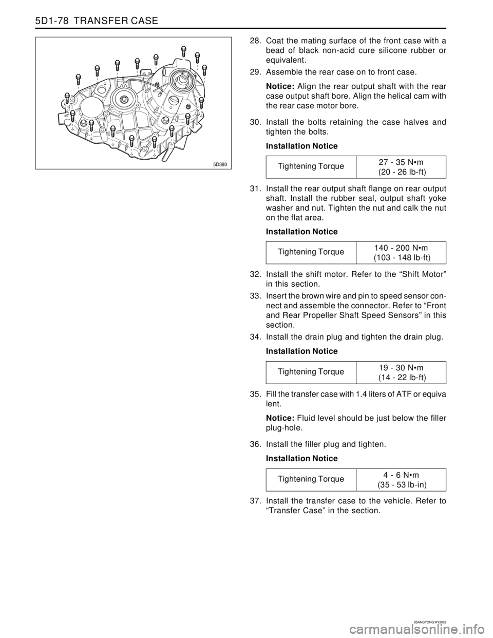
28. Coat the mating surface of the front case with a
bead of black non-acid cure silicone rubber or
equivalent.
29. Assemble the rear case on to front case.
Notice: Align the rear output shaft with the rear
case output shaft bore. Align the helical cam with
the rear case motor bore.
30. Install the bolts retaining the case halves and
tighten the bolts.
Installation Notice
Tightening Torque27 - 35 Nm
(20 - 26 lb-ft)
Tightening Torque140 - 200 Nm
(103 - 148 lb-ft)
Tightening Torque19 - 30 Nm
(14 - 22 lb-ft)
Tightening Torque4 - 6 Nm
(35 - 53 lb-in)
Page 1419 of 2053

SSANGYONG MY2002
5D2-20 TRANSFER CASE (PART TIME - 4408)
������
KAA5D220
ON-VEHICLE SERVICE
MAINTENANCE OF TRANSFER
CASE LUBRICANT
1. Oil Level Check
Clean the oil level plug and surrounding area.
Remove the oil level plug and check whether
oil is drip out or not.
Tighten the oil level plug.
Installation Notice
KAA5D230
MAINTENANCE AND REPAIR
2. Oil Change
Clean the oil level plug and surrounding area
Place a suitable container under the transfer
case.
Remove the oil and tighten the drain plug.
Installation Notice
Fill the oil through the oil level plug until oil
begins to drip out.
Tighten the oil level plug.
3. Cautions for oil level check and plugs tightening
Do not use an impact wrench to remove or
tighten the oil level plug or drain plug since this
will damage the threads in the transfer case.
Tightening Torque4 - 6 Nm
(35 - 53 lb-in)
Tightening Torque20 - 30 Nm
(15 - 22 lb-ft)
Page 1421 of 2053
SSANGYONG MY2002
5D2-22 TRANSFER CASE (PART TIME - 4408)
KAA5D270
KAA5D280
TRANSFER CASE ASSEMBLY
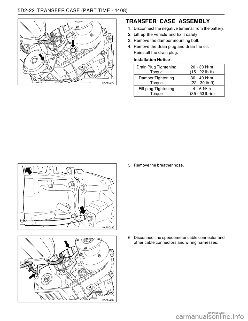
1. Disconnect the negative terminal from the battery.
2. Lift up the vehicle and fix it safely.
3. Remove the damper mounting bolt.
4. Remove the drain plug and drain the oil.
Reinstall the drain plug.
Installation Notice
KAA5D290
5. Remove the breather hose.
6. Disconnect the speedometer cable connector and
other cable connectors and wiring harnesses.20 - 30 Nm
(15 - 22 lb-ft)
30 - 40 Nm
(22 - 30 lb-ft)
4 - 6 Nm
(35 - 53 lb-in)
Drain Plug Tightening
Torque
Damper Tightening
Torque
Fill plug Tightening
Torque
Page 1422 of 2053
TRANSFER CASE (PART TIME - 4408) 5D2-23
SSANGYONG MY2002
KAA5D300
KAA5D310
KAA5D320
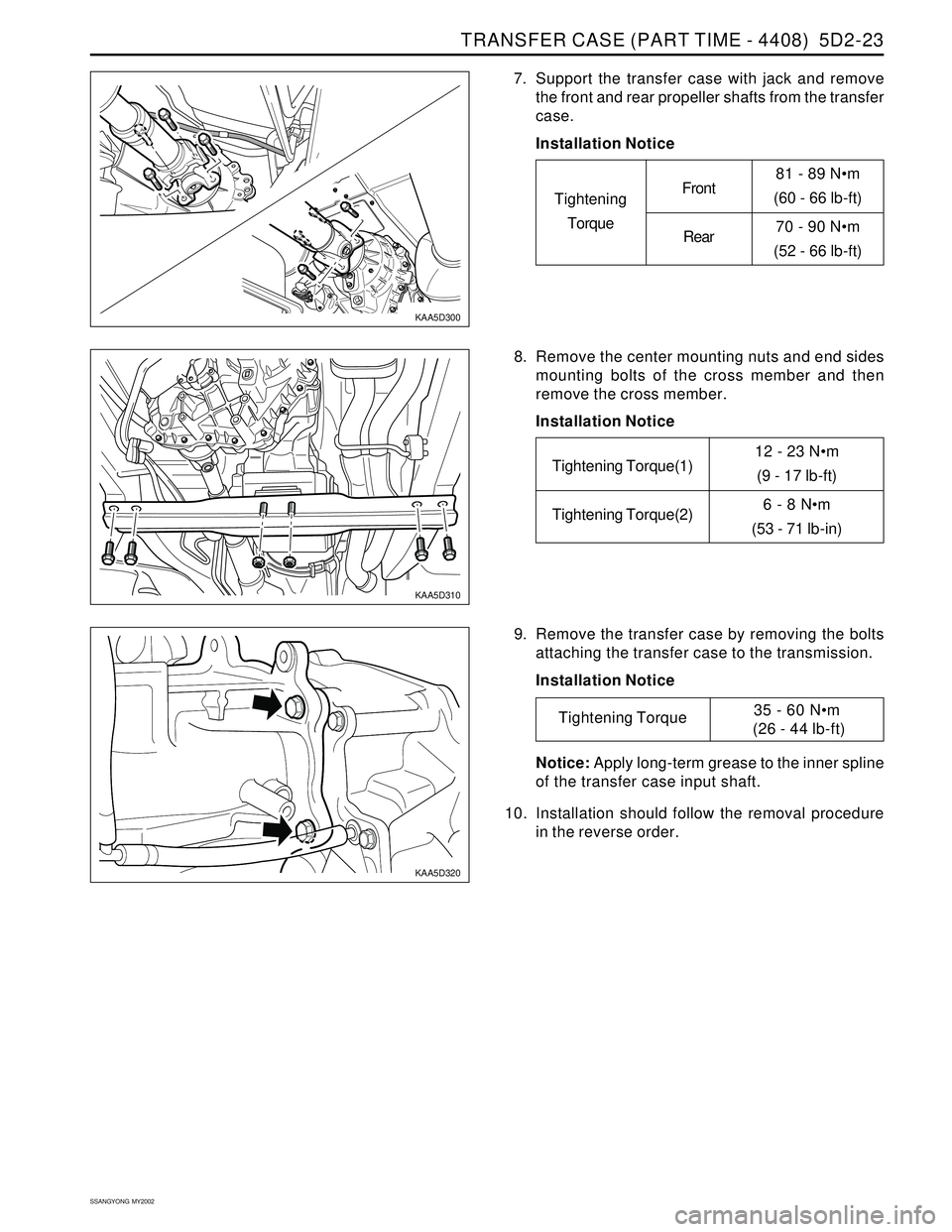
7. Support the transfer case with jack and remove
the front and rear propeller shafts from the transfer
case.
Installation Notice
81 - 89 Nm
(60 - 66 lb-ft)
70 - 90 Nm
(52 - 66 lb-ft)
Tightening
TorqueFront
Rear
12 - 23 Nm
(9 - 17 lb-ft)
6 - 8 Nm
(53 - 71 lb-in)Tightening Torque(1)
Tightening Torque(2)
Tightening Torque35 - 60 Nm
(26 - 44 lb-ft) 8. Remove the center mounting nuts and end sides
mounting bolts of the cross member and then
remove the cross member.
Installation Notice
9. Remove the transfer case by removing the bolts
attaching the transfer case to the transmission.
Installation Notice
Notice: Apply long-term grease to the inner spline
of the transfer case input shaft.
10. Installation should follow the removal procedure
in the reverse order.