SSANGYONG KORANDO 1997 Service Repair Manual
Manufacturer: SSANGYONG, Model Year: 1997, Model line: KORANDO, Model: SSANGYONG KORANDO 1997Pages: 2053, PDF Size: 88.33 MB
Page 441 of 2053

M161 ENGINE CONTROLS 1F2 -- 21
D AEW OO M Y_2000
KAB1F420
Failure
CodeDescriptionTrouble AreaMaintenance Hint
64
No ignition voltage
output (No. 1 ignition
coil)
Malfunction of ignition circuit
Primarycurrentvaluesor
DInspection the ECM pin 70 and 71
about short circuit or open with bad
contact
DInspection the power source to ignition
coil
DInspectiontheignitioncoilhigh
65
No ignition voltage
output (No. 2 ignition
coil)
Primary currentvalues or
secondary short circuitDInspectiontheignition coil,high
tension cords etc.
DInspection the spark plug (wet, cracks,
wear, improper gap, burned
electrodes, heavy deposit)
DInspection the ECM
Circuit Description
The Electronic Ignition (EI) system uses a waste spark method of spark distribution. The Crankshaft Position (CKP)
sensor sends reference pulses to the ECM. The ECM then triggers the EI system ignition coils. Once the ECM triggers
the EI system ignition coils both of the connected spark plugs fire at the same time. One cylinder is on its compression
stroke at the same time that the other is on the exhaust stroke, resulting in lower energy needed to fire the spark plug in
the cylinder on its exhaust stroke.
This leaves the remainder of the high voltage to be used to fire the spark plug in the cylinder on its compression stroke.
Since the CKP sensor is in a fixed position, timing adjustments are not possible or needed.
Page 442 of 2053
1F2 -- 22 M161 ENGINE CONTROLS
D AEW OO M Y_2000
CRANKSHAFT POSITION (CKP) SENSOR
YAA1F940
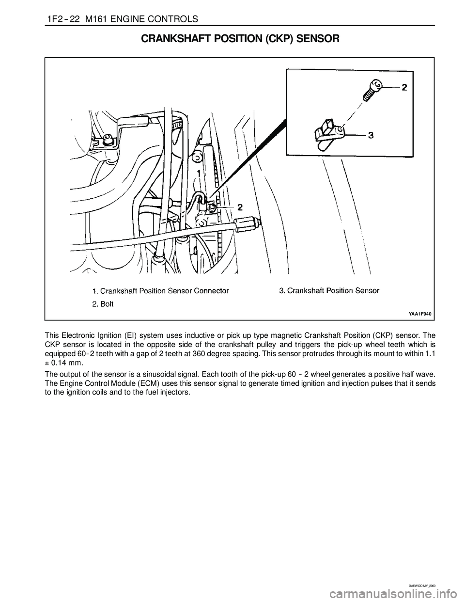
This Electronic Ignition (EI) system uses inductive or pickup type magnetic Crankshaft Position (CKP) sensor. The
CKP sensor is located in the opposite side of the crankshaft pulley and triggers the pick-up wheel teeth which is
equipped 60 -- 2 teeth with a gap of 2 teeth at 360 degree spacing. This sensor protrudes through its mount to within 1.1
±0.14 mm.
The output of the sensor is a sinusoidal signal. Each tooth of the pick-up 60 -- 2 wheel generates a positive half wave.
The Engine Control Module (ECM) uses this sensor signal to generate timed ignition and injection pulses that it sends
to the ignition coils and to the fuel injectors.
Page 443 of 2053
M161 ENGINE CONTROLS 1F2 -- 23
D AEW OO M Y_2000
KAB1F150
Failure
CodeDescriptionTrouble AreaMaintenance Hint
17
Crankshaft position
sensor signal failure (no
engine revolution signal)Even through cam position
recognition is normal, no
crankshaft position signal
recognition.
DMonitoring the actual rpm through or
scan tool
18
Crankshaft position
sensor signal failure
(rpm > max. value)When more than applicable
revolution values or
implausibleto60–2teeth.
scantool
DInspection the ECM pin 100, 99 about
short circuit with bad contact
DInspection the CKP sensor
20
Crankshaft position
sensor signal failure
(gap recognition failure)
When implausible recognition
of cam and crank angle signal
or intermittent sensing the
signal or error count of
undetected gap.
p
DInspection the air gap between sensor
and drive plate
DInspection the drive plate (teeth
condition)
DInspection the ECM
67Crankshaft position
sensor adaptation failureWhen faulty crank angle
sensor adaption.
p
Circuit Description
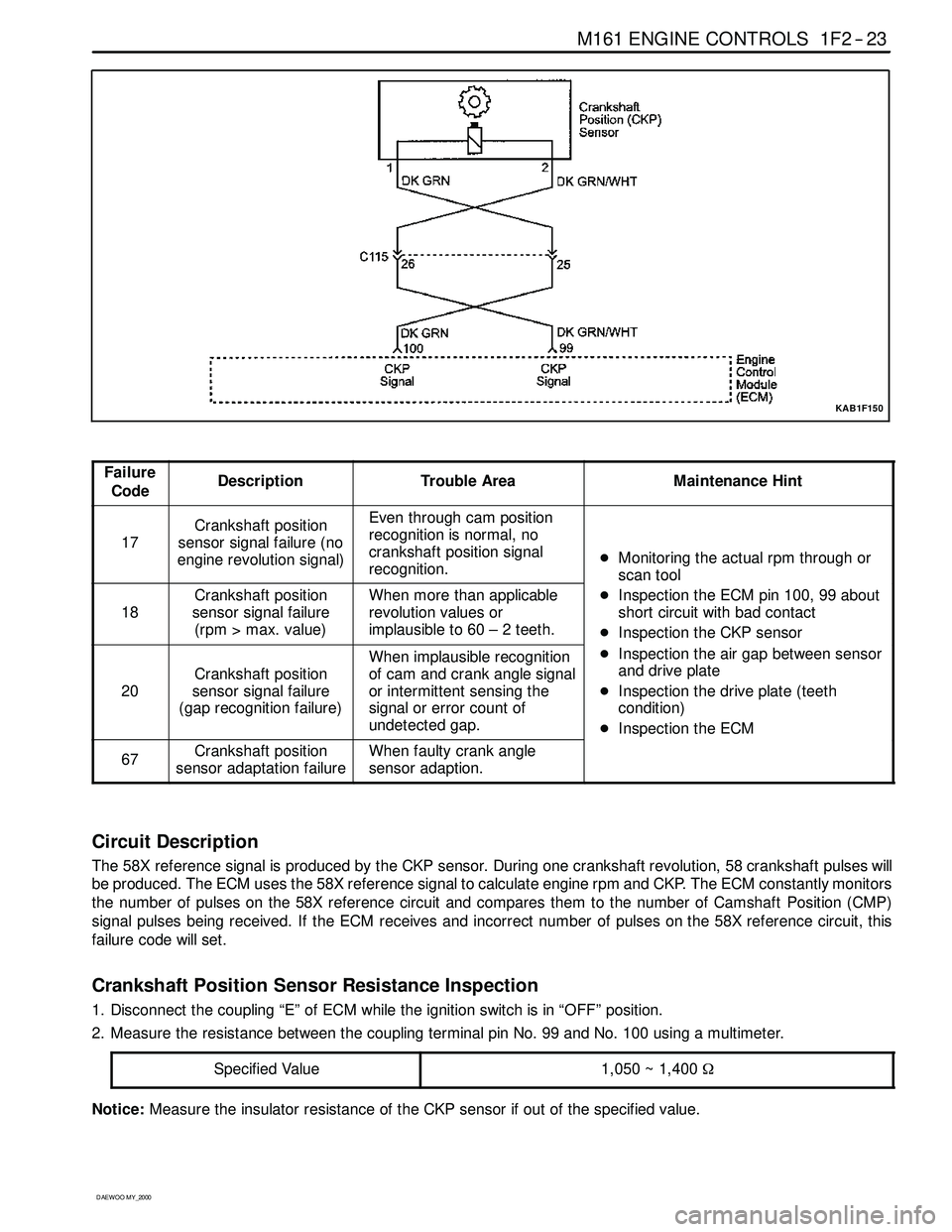
The 58X reference signal is produced by the CKP sensor. During one crankshaft revolution, 58 crankshaft pulseswill
be produced. The ECM uses the 58X reference signal to calculate engine rpm and CKP. The ECM constantly monitors
the number of pulses on the 58X reference circuit and compares them to the number of Camshaft Position (CMP)
signal pulses being received. If the ECM receives and incorrect number of pulses on the 58X reference circuit, this
failure code will set.
Crankshaft Position Sensor Resistance Inspection
1. Disconnect the coupling “E” of ECM while the ignition switch is in “OFF” position.
2. Measure the resistance between the coupling terminal pin No. 99 and No. 100 using a multimeter.
Specified Value
1,050 ~ 1,400Ω
Notice:Measure the insulator resistance of the CKP sensor if out of the specified value.
Page 444 of 2053
1F2 -- 24 M161 ENGINE CONTROLS
D AEW OO M Y_2000
Crankshaft Position Sensor Output Wave Inspection
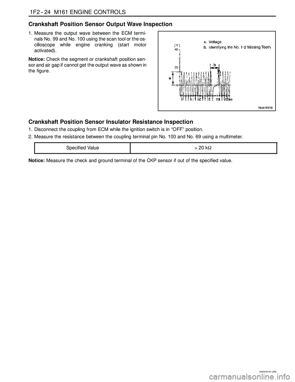
1. Measure the output wave between the ECM termi-
nals No. 99 and No. 100 using the scan tool or the os-
cilloscope whileengine cranking (start motor
activated).
Notice:Check the segment or crankshaft position sen-
sor and air gap if cannot get the output wave as shown in
the figure.
YAA1F270
Crankshaft Position Sensor Insulator Resistance Inspection
1. Disconnect the coupling from ECM while the ignition switch is in “OFF” position.
2. Measure the resistance between the coupling terminal pin No. 100 and No. 69 using a multimeter.
Specified Value
>20 kΩ
Notice:Measure the check and ground terminal of the CKP sensor if out of the specified value.
Page 445 of 2053

M161 ENGINE CONTROLS 1F2 -- 25
D AEW OO M Y_2000
BLANK
Page 446 of 2053
1F2 -- 26 M161 ENGINE CONTROLS
D AEW OO M Y_2000
CAMSHAFT POSITION (CMP) SENSOR
YAA1F950
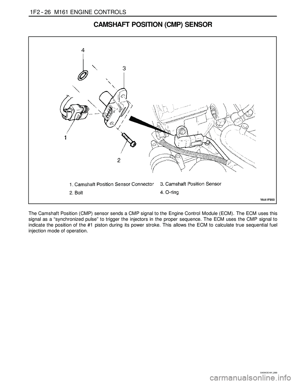
The Camshaft Position (CMP) sensor sends a CMP signal to the Engine Control Module (ECM). The ECM uses this
signal as a “synchronized pulse” to trigger the injectors in the proper sequence. The ECM uses the CMP signal to
indicate the position of the #1 piston during its power stroke. This allows the ECM to calculate true sequential fuel
injection mode of operation.
Page 447 of 2053
M161 ENGINE CONTROLS 1F2 -- 27
D AEW OO M Y_2000
KAB1F430
Failure
CodeDescriptionTrouble AreaMaintenance Hint
19
Camshaft position
sensor signal :
No. 1 cylinder
recognition failureWhen no cam recognition
signal during TN 24 counts
more. (maintain the constant
low or high level)DInspection the source voltage of CMP
sensor
DInspection the ECM pin 106, 104
about short circuit or open with bad
contact
58
Camshaft position
sensor signal : No. 1
cylinder synchronization
failure
When synchronization fault of
cylinder 1 (TDC recognition)
contact
DInspection the CMP sensor
DInspection the damage of sensor or
sprocket
DInspection the ECM
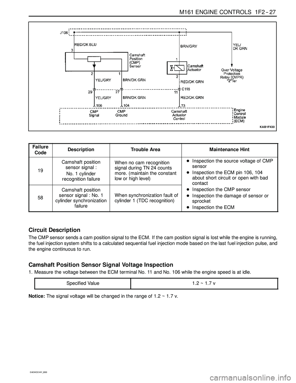
Circuit Description
The CMP sensor sends a cam position signal to the ECM. If the cam position signal is lost while the engine is running,
the fuel injection system shifts to a calculated sequential fuel injection mode based on the last fuel injection pulse, and
the engine continuous to run.
Camshaft Position Sensor Signal Voltage Inspection
1. Measure the voltage between the ECM terminal No. 11 and No. 106 while the engine speed is at idle.
Specified Value
1.2~1.7v
Notice:The signal voltagewill be changed in the range of 1.2 ~ 1.7 v.
Page 448 of 2053
1F2 -- 28 M161 ENGINE CONTROLS
D AEW OO M Y_2000
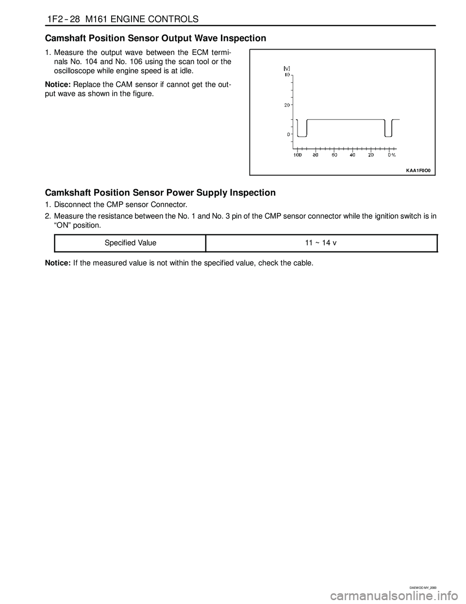
Camshaft Position Sensor Output Wave Inspection
1. Measure the output wave between the ECM termi-
nals No. 104 and No. 106 using the scan tool or the
oscilloscope whileengine speed is at idle.
Notice:Replace the CAM sensor if cannot get the out-
put wave as shown in the figure.
KAA1F0O0
Camkshaft Position Sensor Power Supply Inspection
1. Disconnect the CMP sensor Connector.
2. Measure the resistance between the No. 1 and No. 3 pin of the CMP sensor connector while the ignition switch is in
“ON” position.
Specified Value
11 ~ 14 v
Notice:If the measured value is not within the specified value, check the cable.
Page 449 of 2053

M161 ENGINE CONTROLS 1F2 -- 29
D AEW OO M Y_2000
BLANK
Page 450 of 2053
1F2 -- 32 M161 ENGINE CONTROLS
D AEW OO M Y_2000
KNOCK SENSOR (KS)
YAA1F320
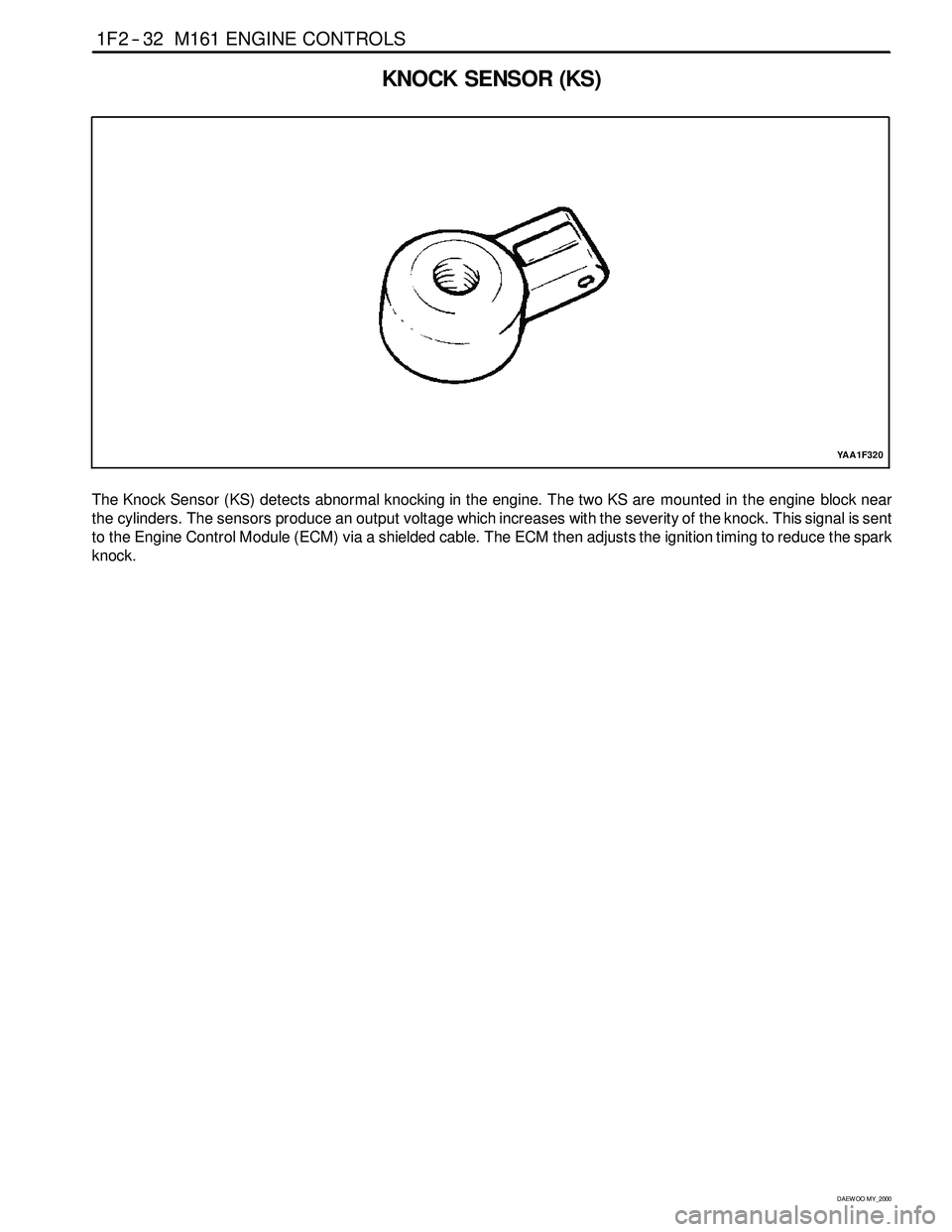
The Knock Sensor (KS) detects abnormal knocking in the engine. The two KS are mounted in the engine block near
the cylinders. The sensors produce an output voltage which increases with the severity of the knock. This signal is sent
to the Engine Control Module (ECM) via a shielded cable. The ECM then adjusts the ignition timing to reduce the spark
knock.