SSANGYONG KORANDO 1997 Service Repair Manual
KORANDO 1997
SSANGYONG
SSANGYONG
https://www.carmanualsonline.info/img/67/57502/w960_57502-0.png
SSANGYONG KORANDO 1997 Service Repair Manual
Page 700 of 2053
OM600 ENGINE MECHANICAL 1B3 -- 151
D AEW OO M Y_2000
TENSIONING RAIL
Preceding Work : Removal of cylinder head
Removal of timing case cover
1 Tensioning Rail2 Bearing Pin
Notice
The plastic coating of the tensioning rail can not be
replaced.
Page 701 of 2053
1B3 -- 152 OM600 ENGINE MECHANICAL
D AEW OO M Y_2000
CYLINDER HEAD GUIDE RAIL
Preceding Work : Removal of the cooling fan
Removal of poly V-- belt
Removal of chain tensioner
1 Cylinder Head Cover
2 Bolt 10N∙m (89 lb-in) .....................
3 Gasket Replace..........................
4 Camshaft Sprocket
5 Washer
6 12-- Sided Bolt (M11)
Inspect, 25N∙m (18 lb-ft)+90_ ..............
7 Tensioning Lever
8 Bolt 23N∙m (17 lb-ft) ......................9 Bearing Pin Sealing Compound.............
10 Guide Rail
11 Bearing Pin
12 Guide Pulley
13 Socket Bolt 23N∙m (17 lb-ft) ................
14 Closing Cover
15 Spring
16 Timing Chain
Page 702 of 2053
OM600 ENGINE MECHANICAL 1B3 -- 153
D AEW OO M Y_2000
Tools Required
115 589 02 34 00 Sliding Hammer
116 589 20 33 00 Threaded Pin
Removal Procedure
1. Removal the cylinder head cover.
2. Pull off the tensioning lever (7) and remove from the
spring (15).
3. Pry off the closing cover (14) and remove the bolt
(13) and then remove the guide pulley (12).
4. Place alignment marks (arrow) on the timing chain
(16) and camshaft sprocket (4).
5. Remove the camshaft sprocket.
Page 703 of 2053
1B3 -- 154 OM600 ENGINE MECHANICAL
D AEW OO M Y_2000
6. Pull out the bearing pins (9, 11) with sliding hammer
and remove the guide rail 10.
Sliding Hammer 116 589 20 33 00
Threaded Pin 116 589 02 34 00
Installation Procedure
1. Apply collar of both bearing pins with sealing com-
pound.
2. Position the guide rail and insert the bearing pins.
3. Install the camshaft sprocket.
Tightening Torque10 N∙m(89lb-in)
Notice
If the max. length ’L’ of the 12-- sided bolt exceeds
53.6mm, replace it.
4. Position the no. 1 cylinder at the TDC of OT.
Page 704 of 2053
OM600 ENGINE MECHANICAL 1B3 -- 155
D AEW OO M Y_2000
In this position, the marking on the camshaft / cam-
shaft bearing cap (arrow) must also be aligned.
5. Install the guide pulley (12).
Tightening Torque23 N∙m (17 lb-ft)
6. Attach the tensioning lever (7) to the spring (15) and
install.
7. Replace the gasket and install the cylinder head
cover.
Tightening Torque10 N∙m(89lb-in)
Page 705 of 2053
1B3 -- 156 OM600 ENGINE MECHANICAL
D AEW OO M Y_2000
TIMING CASE COVER GUIDE RAIL
Preceding Work : Removal of cylinder head cover
1 Bearing Pin
2 Bearing Pin
3 Guide Rail
4 Oil Pump Chain5 Crankshaft
6Spring
7 Bushing
8 Tensioning Lever
Page 706 of 2053
OM600 ENGINE MECHANICAL 1B3 -- 157
D AEW OO M Y_2000
Removal Procedure
1. Pull out the tensioning lever (8) together with the
spring (6) and guide rail (3) far enough until the ten-
sioning lever has moved passed the oil pump chain
(4) and is resting against the crankshaft (5)
2. Pull the tensioning lever (8) off the bearing pin (2)
and carefully remove the spring (6). Remove the
tensioning lever (8) together with the spring (6) and
bushing (7).
3. Remove the guide rail (3).
Installation Procedure
1. Install the guide rail (3). Attach the spring (6) to the
guide rail and to the tensioning lever (8).
Notice
Ensure that the spring is correctly located in the
guide rail (arrow).
2. Push the guide rail, spring, bushing and tensioning
lever together onto the bearing pin (1, 2).
Page 707 of 2053
1B3 -- 158 OM600 ENGINE MECHANICAL
D AEW OO M Y_2000
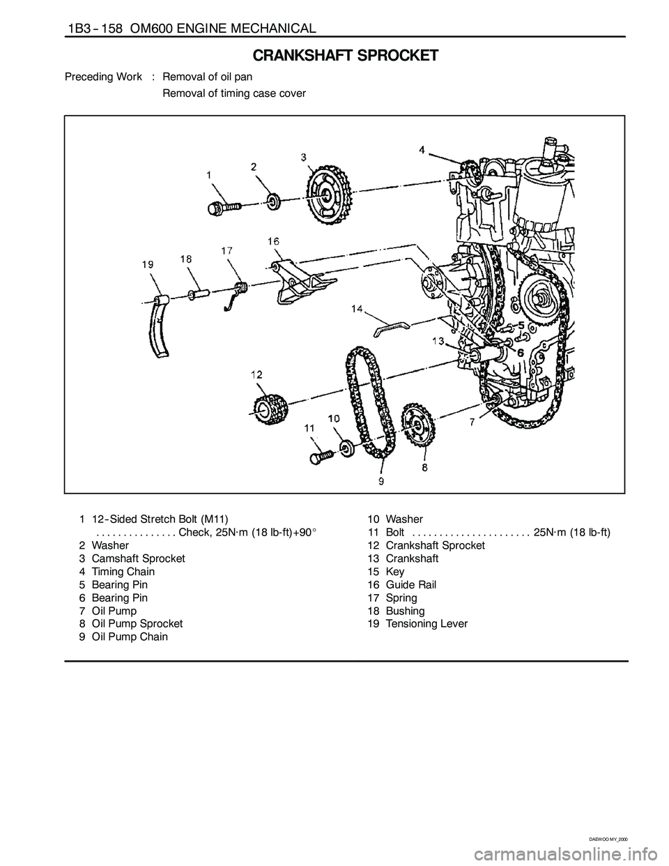
CRANKSHAFT SPROCKET
Preceding Work : Removal of oil pan
Removal of timing case cover
1 12-- Sided Stretch Bolt (M11)
Check, 25N∙m (18 lb-ft)+90_ ...............
2 Washer
3 Camshaft Sprocket
4 Timing Chain
5 Bearing Pin
6 Bearing Pin
7OilPump
8 Oil Pump Sprocket
9 Oil Pump Chain10 Washer
11 Bolt 25N∙m (18 lb-ft) ......................
12 Crankshaft Sprocket
13 Crankshaft
15 Key
16 Guide Rail
17 Spring
18 Bushing
19 Tensioning Lever
Page 708 of 2053
OM600 ENGINE MECHANICAL 1B3 -- 159
D AEW OO M Y_2000
Special Tools
116 589 07 15 00 Drift
102589053300 Puller
Removal Procedure
1. Pull out the tensioning lever (19) together with the
spring (17) and guide rail (16) far enough until the
tensioning lever has passed the oil pump chain (9)
and is resting against the crankshaft (13).
2. Pull out tensioning lever (19), spring (17) and bush-
ing (18) from the bearing pin (6).
3. Pull out the guide rail (16).
4. Remove the bolt(11) and then remove the washer
(10), oil pump chin (9) and sprocket (8).
Page 709 of 2053
1B3 -- 160 OM600 ENGINE MECHANICAL
D AEW OO M Y_2000
5. Place alignment marks (arrow) on the timing chain
(4) and crankshaft sprocket (12).
6. Remove the woodruff key(15).
7. Place alignment marks (arrow) on the timing chain
(4) and camshaft sprocket (3).
8. Remove the chain tensioner.
9. Remove the bolt (1) and then remove the washer (2)
and camshaft sprocket (3).
10. Remove the crankshaft sprocket (12) by using a
puller (20).
Puller 102 589 05 33 00


