SSANGYONG NEW ACTYON SPORTS 2013 Service Manual
Manufacturer: SSANGYONG, Model Year: 2013, Model line: NEW ACTYON SPORTS, Model: SSANGYONG NEW ACTYON SPORTS 2013Pages: 751, PDF Size: 72.63 MB
Page 721 of 751

02-12
3. OPERATION PROCESS
The overall air bag operation process and its functions and roles are broadly explained in this block
diagram. This diagram summarizes and highlights the functions adopted by Ssangyoung Motors.
1) Air Bag System Block Diagram
Page 722 of 751

02-138810-01
Page 723 of 751
02-14
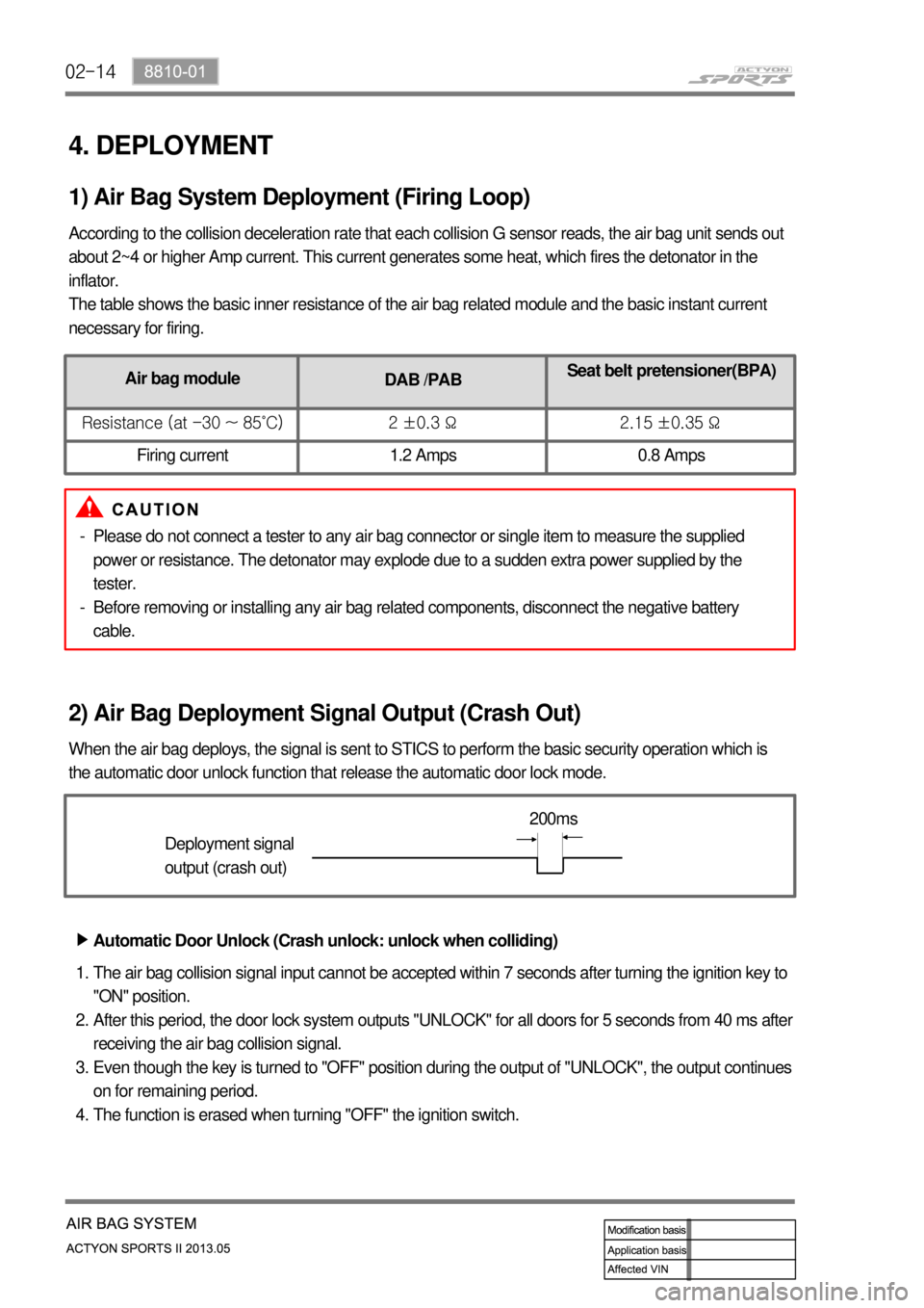
4. DEPLOYMENT
According to the collision deceleration rate that each collision G sensor reads, the air bag unit sends out
about 2~4 or higher Amp current. This current generates some heat, which fires the detonator in the
inflator.
The table shows the basic inner resistance of the air bag related module and the basic instant current
necessary for firing.
1) Air Bag System Deployment (Firing Loop)
2) Air Bag Deployment Signal Output (Crash Out)
When the air bag deploys, the signal is sent to STICS to perform the basic security operation which is
the automatic door unlock function that release the automatic door lock mode.
Deployment signal
output (crash out)200ms
Automatic Door Unlock (Crash unlock: unlock when colliding) ▶
The air bag collision signal input cannot be accepted within 7 seconds after turning the ignition key to
"ON" position.
After this period, the door lock system outputs "UNLOCK" for all doors for 5 seconds from 40 ms after
receiving the air bag collision signal.
Even though the key is turned to "OFF" position during the output of "UNLOCK", the output continues
on for remaining period.
The function is erased when turning "OFF" the ignition switch. 1.
2.
3.
4.
Air bag module
DAB /PABSeat belt pretensioner(BPA)
Resistance (at -30 ~ 85˚C) 2 ±0.3 Ω 2.15 ±0.35 Ω
Firing current 1.2 Amps 0.8 Amps
Please do not connect a tester to any air bag connector or single item to measure the supplied
power or resistance. The detonator may explode due to a sudden extra power supplied by the
tester.
Before removing or installing any air bag related components, disconnect the negative battery
cable. -
-
Page 724 of 751

02-158810-01
The "Unlock" control by air bag signal prevails over any "LOCK" or "UNLOCK" control by other
functions.
The "LOCK/UNLOCK" request by other functions will be ignored after/during the output of
"UNLOCK" by the air bag.
However, the door lock is controlled by other functions when the ignition switch is "OFF".
"LOCK" (or "UNLOCK") output is ignored if "LOCK" (or "UNLOCK") output is required while
performing the output of "LOCK" (or "UNLOCK").
However, UNLOCK by air bag signal and operation by the remote control key are valid.
If the door lock system outputs "LOCK" and "UNLOCK" simultaneously, only the "LOCK" output can
be activated. 1.
2.
3.
4.Cautions for Door Lock/Unlock Control ▶
ING KEY
SW(*1)
Deployment
signal
Door unlock
relayON
OFF
ON
OFF
ON
OFF
T1 : 200ms T2 : 40ms T3 : 5s T3 T2 T1
Page 725 of 751
02-16
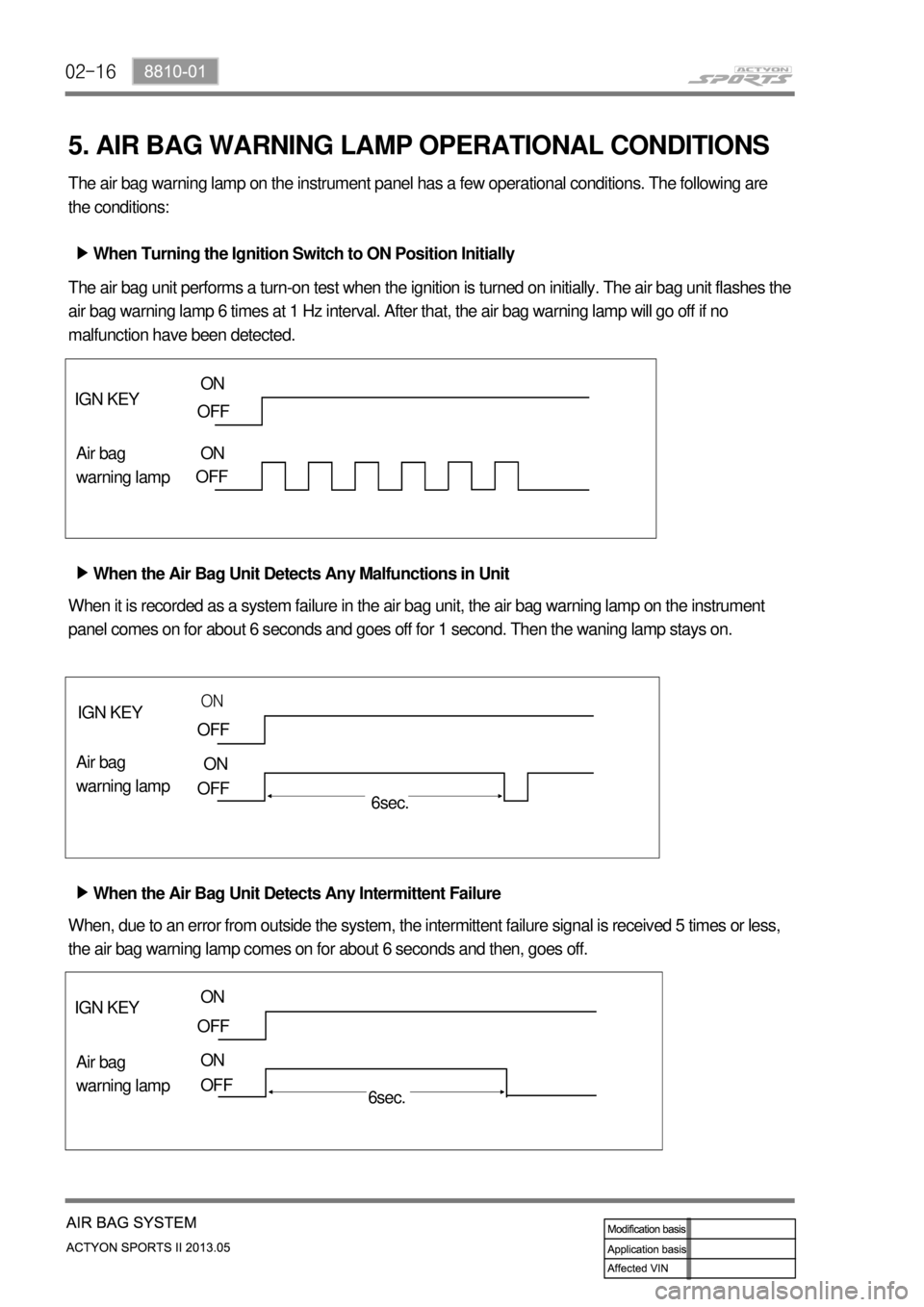
5. AIR BAG WARNING LAMP OPERATIONAL CONDITIONS
The air bag warning lamp on the instrument panel has a few operational conditions. The following are
the conditions:
When Turning the Ignition Switch to ON Position Initially ▶
The air bag unit performs a turn-on test when the ignition is turned on initially. The air bag unit flashes the
air bag warning lamp 6 times at 1 Hz interval. After that, the air bag warning lamp will go off if no
malfunction have been detected.
When the Air Bag Unit Detects Any Malfunctions in Unit ▶
When the Air Bag Unit Detects Any Intermittent Failure ▶ When it is recorded as a system failure in the air bag unit, the air bag warning lamp on the instrument
panel comes on for about 6 seconds and goes off for 1 second. Then the waning lamp stays on.
When, due to an error from outside the system, the intermittent failure signal is received 5 times or less,
the air bag warning lamp comes on for about 6 seconds and then, goes off.
IGN KEY
Air bag
warning lamp
IGN KEY
Air bag
warning lamp IGN KEY
Air bag
warning lamp
ON
OFF
OFF ON
OFF
ON
OFF
ON
OFF
ON
OFF
6sec.
6sec. ON
Page 726 of 751

02-178810-01
6. CIRCUIT DIAGRAM
Page 727 of 751
03-37410-01
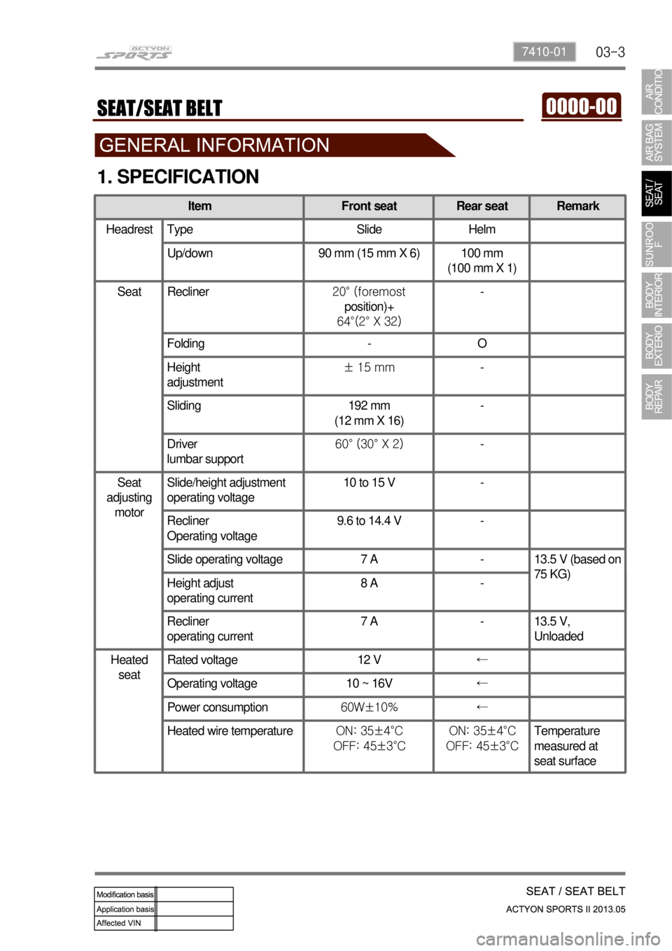
1. SPECIFICATION
Item Front seat Rear seat Remark
Headrest Type Slide Helm
Up/down 90 mm (15 mm X 6) 100 mm
(100 mm X 1)
Seat Recliner20° (foremost
position)+
64°(2° X 32)-
Folding - O
Height
adjustment ± 15 mm-
Sliding 192 mm
(12 mm X 16)-
Driver
lumbar support60° (30° X 2)-
Seat
adjusting
motor Slide/height adjustment
operating voltage 10 to 15 V -
Recliner
Operating voltage9.6 to 14.4 V -
Slide operating voltage 7 A - 13.5 V (based on
75 KG)
Height adjust
operating current8 A -
Recliner
operating current 7 A - 13.5 V,
Unloaded
Heated
seatRated voltage 12 V←
Operating voltage 10 ~ 16V←
Power consumption60W±10% ←
Heated wire temperatureON: 35±4°C
OFF: 45±3°CON: 35±4°C
OFF: 45±3°CTemperature
measured at
seat surface
Page 728 of 751
03-4
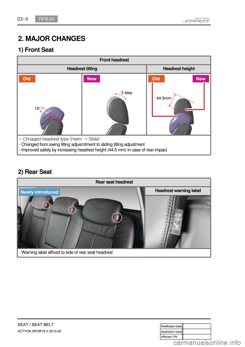
2. MAJOR CHANGES
1) Front Seat
Front headrest
Headrest tilting Headrest height
- Chnaged headrest type (Helm → Slide)
- Changed from swing tilting adjusmtment to sliding tilting adjustment
- Improved safety by increasing headrest height (44.5 mm) in case of rear impact
2) Rear Seat
Rear seat headrest
- Warning label affixed to side of rear seat headrest
Headrest warning label
Page 729 of 751

03-57410-01
Rear RH seat
Fabric seat Leather seat
- 2 different heating wires according to fabric and leather specification
Page 730 of 751
03-6
3. WARNINGS FOR POWER SEAT
Adjust the driver's seat before driving.
Make sure that the seat is firmly secured after adjusting.
Never drive the vehicle with the head restraint removed or lowered excessively. Otherwise, your neck,
spine or other parts of the body can be severely injured in the event of an accident.
If you recline the seatback excessively, you could slide under the seat belt and be injured severely in a
collision.
Do not put any object that could damage the seat on the seat.
The front and rear seats are equipped with the heated wire (seat warmer) system. Using the seat
warmer system excessively may cause minor burns. The following occupants should exercise special
care when using the heated wire seat. 1.
2.
3.
4.
5.
6.
Infant, child, old or handicapped person
Person with sensitive skin
Exhausted person
Persons who is drunk or took medicine which causes drowsiness such as sleeping pills, cold
tablets, etc. -
-
-
-
Do not place anything on the seat that insulates against the heat, such as a blanket or cushion.
Make sure that the head restraints are in place and secured properly. Never drive the vehicle with the
head restraint removed.
To minimize the injuries in a collision or an abrupt stop, make sure the seatback is in the upright
position before driving. If the seatback is reclined too much, the occupant could slide under the seat
belt in a collision or an abrupt stop and cannot be protected properly by the airbag system. 7.
5.
9.
4. CAUTIONS FOR POWER SEAT
You can operate the power seat with the ignition switch OFF. However, frequent operation of the seat
switch with the engine stopped can result in battery becoming discharged.
Operating more than one seat adjustment switch at the same time can cause damage to the seat
motor. Therefore, operate the seat switch only one at a time.
Do not use organic solvents such as benzene, thinner, alcohol or gasoline to prevent the seat cover
from being damaged while cleaning.
Do not operate the seat position adjustment switch forcefully when the seat does not move or it
contacts an object.
If the power seat is not operated, check and correct the problem before driving off. 1.
2.
3.
4.
5.