SUBARU FORESTER 1999 Service Repair Manual
Manufacturer: SUBARU, Model Year: 1999, Model line: FORESTER, Model: SUBARU FORESTER 1999Pages: 345, PDF Size: 5.6 MB
Page 181 of 345
![SUBARU FORESTER 1999 Service Repair Manual 4.
S5M0393A
\(1\)
\(2\)\(3\)
\(4\)\(5\)
25
[C400]5-1COMPONENT
4. SUBARU FORESTER 1999 Service Repair Manual 4.
S5M0393A
\(1\)
\(2\)\(3\)
\(4\)\(5\)
25
[C400]5-1COMPONENT
4.](/img/17/57427/w960_57427-180.png)
4.
S5M0393A
\(1\)
\(2\)\(3\)
\(4\)\(5\)
25
[C400]5-1COMPONENT
4.
Page 182 of 345
![SUBARU FORESTER 1999 Service Repair Manual 5.
S5M0146A
\(1\)
\(2\)TT:
25\2617\2610.7,\2615.1\)
26
5-1[C500]COMPONENT
5. SUBARU FORESTER 1999 Service Repair Manual 5.
S5M0146A
\(1\)
\(2\)TT:
25\2617\2610.7,\2615.1\)
26
5-1[C500]COMPONENT
5.](/img/17/57427/w960_57427-181.png)
5.
S5M0146A
\(1\)
\(2\)TT:
25\2617\2610.7,\2615.1\)
26
5-1[C500]COMPONENT
5.
Page 183 of 345
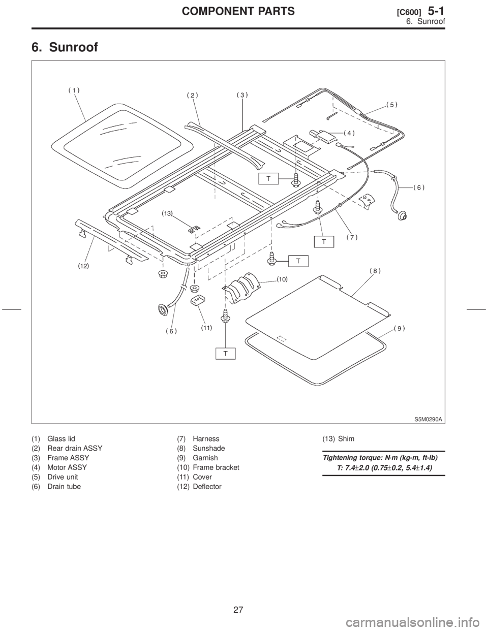
6. Sunroof
S5M0290A
(1) Glass lid
(2) Rear drain ASSY
(3) Frame ASSY
(4) Motor ASSY
(5) Drive unit
(6) Drain tube(7) Harness
(8) Sunshade
(9) Garnish
(10) Frame bracket
(11) Cover
(12) Deflector(13) Shim
Tightening torque: N´m (kg-m, ft-lb)
T:
7.4±2.0 (0.75±0.2, 5.4±1.4)
27
[C600]5-1COMPONENT PARTS
6. Sunroof
Page 184 of 345
![SUBARU FORESTER 1999 Service Repair Manual 7.
S5M0147A
\(1\)
\(2\)TT:
32\26110\2611.0,\2617.2\)
28
5-1[C700]COMPONENT
7. SUBARU FORESTER 1999 Service Repair Manual 7.
S5M0147A
\(1\)
\(2\)TT:
32\26110\2611.0,\2617.2\)
28
5-1[C700]COMPONENT
7.](/img/17/57427/w960_57427-183.png)
7.
S5M0147A
\(1\)
\(2\)TT:
32\26110\2611.0,\2617.2\)
28
5-1[C700]COMPONENT
7.
Page 185 of 345
1. Hood
A: REMOVAL AND INSTALLATION
NOTE:
The hood lock has a dual locking design which
consists of a main lock and a safety lock mecha-
nism. When the release knob located at the front
pillar on the driver's side is pulled back, the main
lock is released through the cable attached to the
knob.
The safety lock can be released by pushing the
lever protruding above the front grill while opening
the hood.
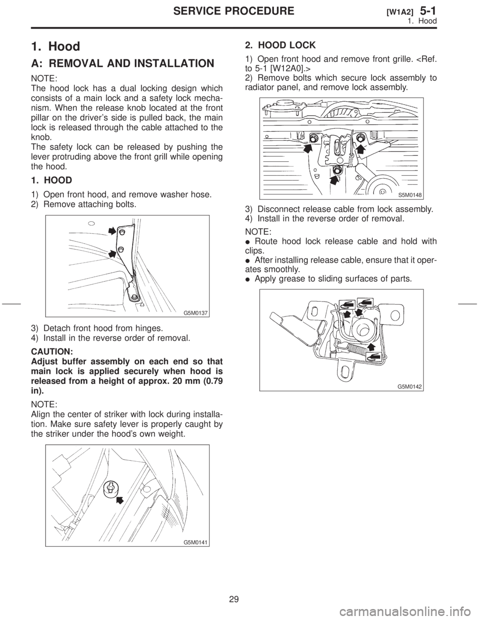
1. HOOD
1) Open front hood, and remove washer hose.
2) Remove attaching bolts.
G5M0137
3) Detach front hood from hinges.
4) Install in the reverse order of removal.
CAUTION:
Adjust buffer assembly on each end so that
main lock is applied securely when hood is
released from a height of approx. 20 mm (0.79
in).
NOTE:
Align the center of striker with lock during installa-
tion. Make sure safety lever is properly caught by
the striker under the hood's own weight.
G5M0141
2. HOOD LOCK
1) Open front hood and remove front grille.
2) Remove bolts which secure lock assembly to
radiator panel, and remove lock assembly.
S5M0148
3) Disconnect release cable from lock assembly.
4) Install in the reverse order of removal.
NOTE:
IRoute hood lock release cable and hold with
clips.
IAfter installing release cable, ensure that it oper-
ates smoothly.
IApply grease to sliding surfaces of parts.
G5M0142
29
[W1A2]5-1SERVICE PROCEDURE
1. Hood
Page 186 of 345
![SUBARU FORESTER 1999 Service Repair Manual 3. RELEASE CABLE
1) Remove front grille. <Ref. to 5-1 [W12A0].>
2) Remove release cable from lock assembly.
<Ref. to 5-1 [W1A2].>
3) Remove cable clip from engine compartment.
4) While disengaging cab SUBARU FORESTER 1999 Service Repair Manual 3. RELEASE CABLE
1) Remove front grille. <Ref. to 5-1 [W12A0].>
2) Remove release cable from lock assembly.
<Ref. to 5-1 [W1A2].>
3) Remove cable clip from engine compartment.
4) While disengaging cab](/img/17/57427/w960_57427-185.png)
3. RELEASE CABLE
1) Remove front grille.
2) Remove release cable from lock assembly.
3) Remove cable clip from engine compartment.
4) While disengaging cable from opener lever,
remove opener lever from front pillar.
S5M0149
5) Remove release cable.
6) Install in the reverse order of removal.
B: POINTS TO CHECK
1) Check striker for bending or abnormal wear.
2) Check safety lever for improper movement.
3) Check other levers and spring for rust formation
and rough movement.
G5M0140
C: ADJUSTMENT
1) Fore-aft and left-right adjustments
Loosen striker mounting bolts and adjust fore-and-
aft position of striker.
CAUTION:
Do not adjust striker position using the lock.
Doing so may result in a misaligned front grille.
G5M0143
2) Up-down adjustment
Make up-and-down adjustment of striker only
when hood does not properly contact buffer or
hood is not flush with fender, or when release cable
does not properly operate. Adjustment can be
made by adjusting the stroke length of the striker
after lock assembly mounting screws are removed.
30
5-1[W1A3]SERVICE PROCEDURE
1. Hood
Page 187 of 345
2. Fuel Flap
A: REMOVAL AND INSTALLATION
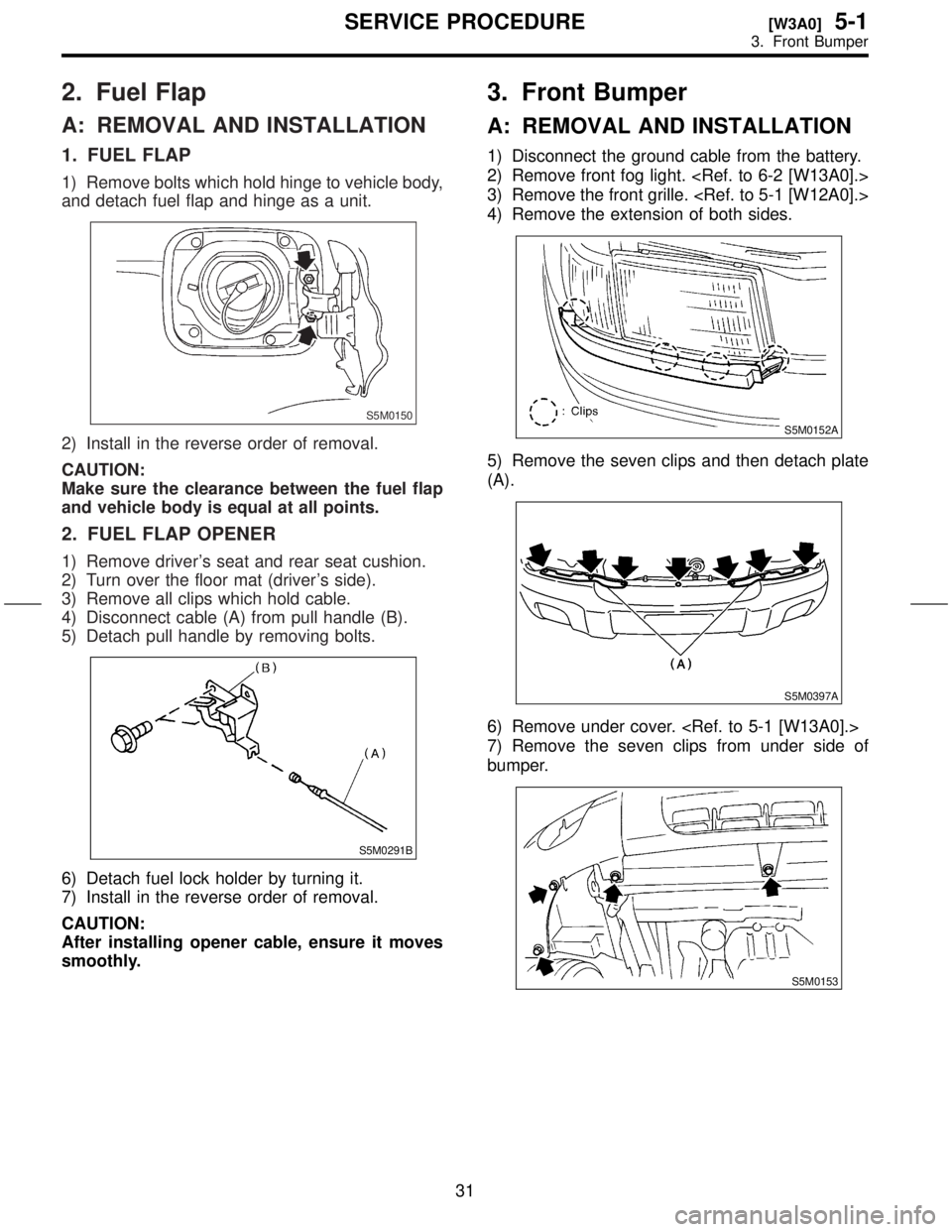
1. FUEL FLAP
1) Remove bolts which hold hinge to vehicle body,
and detach fuel flap and hinge as a unit.
S5M0150
2) Install in the reverse order of removal.
CAUTION:
Make sure the clearance between the fuel flap
and vehicle body is equal at all points.
2. FUEL FLAP OPENER
1) Remove driver's seat and rear seat cushion.
2) Turn over the floor mat (driver's side).
3) Remove all clips which hold cable.
4) Disconnect cable (A) from pull handle (B).
5) Detach pull handle by removing bolts.
S5M0291B
6) Detach fuel lock holder by turning it.
7) Install in the reverse order of removal.
CAUTION:
After installing opener cable, ensure it moves
smoothly.
3. Front Bumper
A: REMOVAL AND INSTALLATION
1) Disconnect the ground cable from the battery.
2) Remove front fog light.
3) Remove the front grille.
4) Remove the extension of both sides.
S5M0152A
5) Remove the seven clips and then detach plate
(A).
S5M0397A
6) Remove under cover.
7) Remove the seven clips from under side of
bumper.
S5M0153
31
[W3A0]5-1SERVICE PROCEDURE
3. Front Bumper
Page 188 of 345
2. Fuel Flap
A: REMOVAL AND INSTALLATION
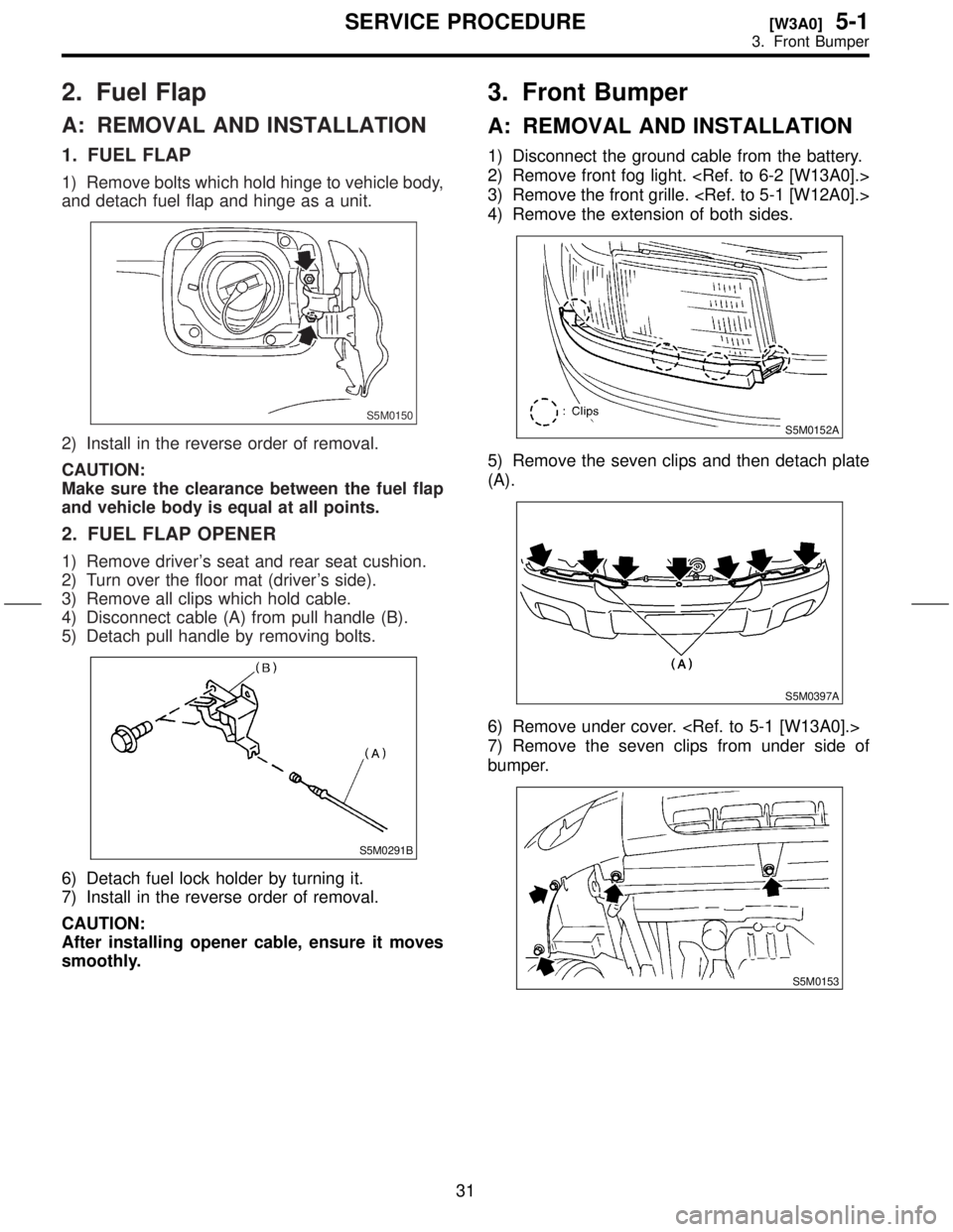
1. FUEL FLAP
1) Remove bolts which hold hinge to vehicle body,
and detach fuel flap and hinge as a unit.
S5M0150
2) Install in the reverse order of removal.
CAUTION:
Make sure the clearance between the fuel flap
and vehicle body is equal at all points.
2. FUEL FLAP OPENER
1) Remove driver's seat and rear seat cushion.
2) Turn over the floor mat (driver's side).
3) Remove all clips which hold cable.
4) Disconnect cable (A) from pull handle (B).
5) Detach pull handle by removing bolts.
S5M0291B
6) Detach fuel lock holder by turning it.
7) Install in the reverse order of removal.
CAUTION:
After installing opener cable, ensure it moves
smoothly.
3. Front Bumper
A: REMOVAL AND INSTALLATION
1) Disconnect the ground cable from the battery.
2) Remove front fog light.
3) Remove the front grille.
4) Remove the extension of both sides.
S5M0152A
5) Remove the seven clips and then detach plate
(A).
S5M0397A
6) Remove under cover.
7) Remove the seven clips from under side of
bumper.
S5M0153
31
[W3A0]5-1SERVICE PROCEDURE
3. Front Bumper
Page 189 of 345
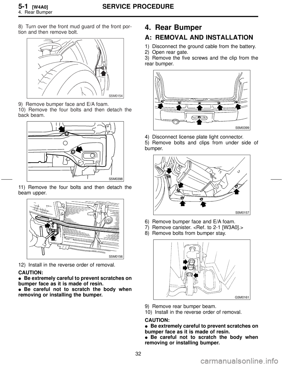
8) Turn over the front mud guard of the front por-
tion and then remove bolt.
S5M0154
9) Remove bumper face and E/A foam.
10) Remove the four bolts and then detach the
back beam.
S5M0398
11) Remove the four bolts and then detach the
beam upper.
S5M0156
12) Install in the reverse order of removal.
CAUTION:
IBe extremely careful to prevent scratches on
bumper face as it is made of resin.
IBe careful not to scratch the body when
removing or installing the bumper.
4. Rear Bumper
A: REMOVAL AND INSTALLATION
1) Disconnect the ground cable from the battery.
2) Open rear gate.
3) Remove the five screws and the clip from the
rear bumper.
S5M0399
4) Disconnect license plate light connector.
5) Remove bolts and clips from under side of
bumper.
S5M0157
6) Remove bumper face and E/A foam.
7) Remove canister.
8) Remove bolts from bumper stay.
G5M0161
9) Remove rear bumper beam.
10) Install in the reverse order of removal.
CAUTION:
IBe extremely careful to prevent scratches on
bumper face as it is made of resin.
IBe careful not to scratch the body when
removing or installing bumper.
32
5-1[W4A0]SERVICE PROCEDURE
4. Rear Bumper
Page 190 of 345
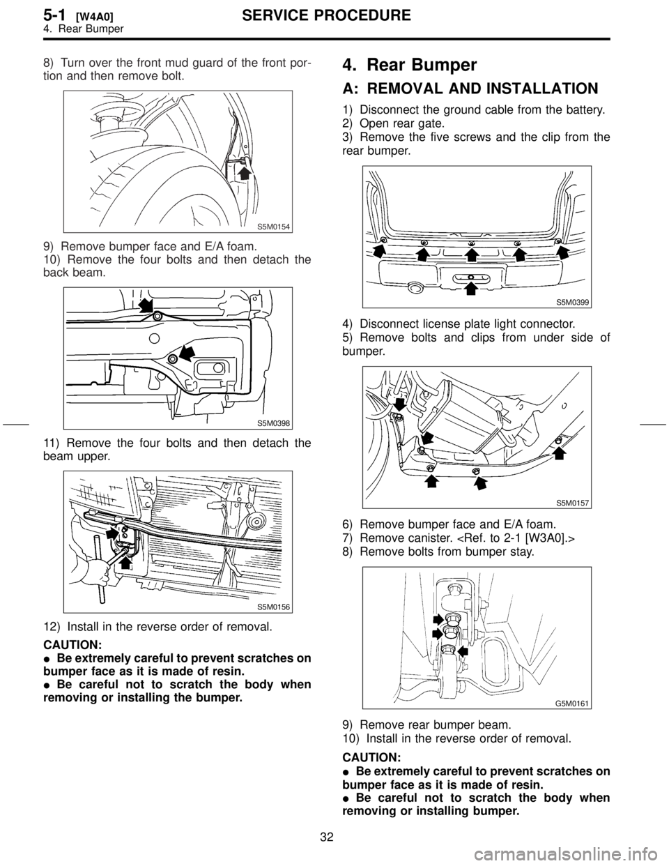
8) Turn over the front mud guard of the front por-
tion and then remove bolt.
S5M0154
9) Remove bumper face and E/A foam.
10) Remove the four bolts and then detach the
back beam.
S5M0398
11) Remove the four bolts and then detach the
beam upper.
S5M0156
12) Install in the reverse order of removal.
CAUTION:
IBe extremely careful to prevent scratches on
bumper face as it is made of resin.
IBe careful not to scratch the body when
removing or installing the bumper.
4. Rear Bumper
A: REMOVAL AND INSTALLATION
1) Disconnect the ground cable from the battery.
2) Open rear gate.
3) Remove the five screws and the clip from the
rear bumper.
S5M0399
4) Disconnect license plate light connector.
5) Remove bolts and clips from under side of
bumper.
S5M0157
6) Remove bumper face and E/A foam.
7) Remove canister.
8) Remove bolts from bumper stay.
G5M0161
9) Remove rear bumper beam.
10) Install in the reverse order of removal.
CAUTION:
IBe extremely careful to prevent scratches on
bumper face as it is made of resin.
IBe careful not to scratch the body when
removing or installing bumper.
32
5-1[W4A0]SERVICE PROCEDURE
4. Rear Bumper