SUBARU FORESTER 2004 Service Repair Manual
FORESTER 2004
SUBARU
SUBARU
https://www.carmanualsonline.info/img/17/57426/w960_57426-0.png
SUBARU FORESTER 2004 Service Repair Manual
Trending: weight, jump cable, seats, spark plugs, timing belt, rear view mirror, air pressure switch
Page 321 of 2870
FUJI HEAVY INDUSTRIES LTD. G8080GE7
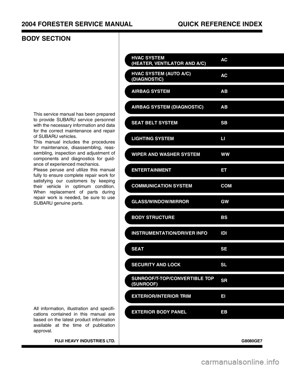
2004 FORESTER SERVICE MANUAL QUICK REFERENCE INDEX
BODY SECTION
This service manual has been prepared
to provide SUBARU service personnel
with the necessary information and data
for the correct maintenance and repair
of SUBARU vehicles.
This manual includes the procedures
for maintenance, disassembling, reas-
sembling, inspection and adjustment of
components and diagnostics for guid-
ance of experienced mechanics.
Please peruse and utilize this manual
fully to ensure complete repair work for
satisfying our customers by keeping
their vehicle in optimum condition.
When replacement of parts during
repair work is needed, be sure to use
SUBARU genuine parts.
All information, illustration and specifi-
cations contained in this manual are
based on the latest product information
available at the time of publication
approval.HVAC SYSTEM
(HEATER, VENTILATOR AND A/C)AC
HVAC SYSTEM (AUTO A/C)
(DIAGNOSTIC)AC
AIRBAG SYSTEM AB
AIRBAG SYSTEM (DIAGNOSTIC) AB
SEAT BELT SYSTEM SB
LIGHTING SYSTEM LI
WIPER AND WASHER SYSTEM WW
ENTERTAINMENT ET
COMMUNICATION SYSTEM COM
GLASS/WINDOW/MIRROR GW
BODY STRUCTURE BS
INSTRUMENTATION/DRIVER INFO IDI
SEAT SE
SECURITY AND LOCK SL
SUNROOF/T-TOP/CONVERTIBLE TOP
(SUNROOF)SR
EXTERIOR/INTERIOR TRIM EI
EXTERIOR BODY PANEL EB
Page 322 of 2870
2004 FORESTER SERVICE MANUAL QUICK REFERENCE INDEX
BODY SECTION
G8080GE7
CRUISE CONTROL SYSTEM CC
CRUISE CONTROL SYSTEM
(DIAGNOSTIC)CC(H4SO)
CRUISE CONTROL SYSTEM
(DIAGNOSTIC)CC(H4DOTC)
CRUISE CONTROL SYSTEM
(DIAGNOSTIC)CC(H4DOTC 2.5)
IMMOBILIZER (DIAGNOSTIC) IM
Page 323 of 2870
COMMUNICATION SYSTEM
COM
Page
1. General Description ....................................................................................2
2. Horn System ...............................................................................................3
3. Horn ............................................................................................................4
4. Horn Switch .................................................................................................5
Page 324 of 2870
COM-2
COMMUNICATION SYSTEM
General Description
1. General Description
A: CAUTION
Before disassembling or reassembling parts, al-
ways disconnect the battery ground cable. When re-
placing radio, control module and other parts
provided with memory functions, record memory con-
tents before disconnecting the battery ground cable.
Otherwise, the memory will be erased.
Reassemble in reverse order of disassembly, un-
less otherwise indicated.
Adjust parts to the given specifications.
Connect the connectors and hoses securely dur-
ing reassembly.
After reassembly, make sure functional parts op-
erate smoothly.
B: PREPARATION TOOL
1. GENERAL TOOL
TO OL
NAMEREMARKS
Circuit
testerUsed for measuring resistance and voltage.
Page 325 of 2870
COM-3
COMMUNICATION SYSTEM
Horn System
2. Horn System
A: WIRING DIAGRAM
1. HORN
tem.>
B: INSPECTION
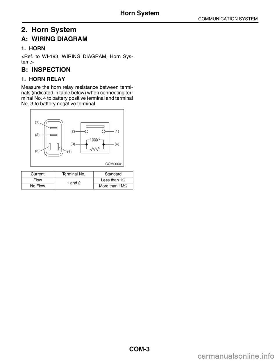
1. HORN RELAY
Measure the horn relay resistance between termi-
nals (indicated in table below) when connecting ter-
minal No. 4 to battery positive terminal and terminal
No. 3 to battery negative terminal.
Current Terminal No. Standard
Flow
1 and 2Less than 1Ω
No Flow More than 1MΩ
COM00001
(1)
(2) (1)
(4)(2)
(3)
(3)(4)
Page 326 of 2870
COM-4
COMMUNICATION SYSTEM
Horn
3. Horn
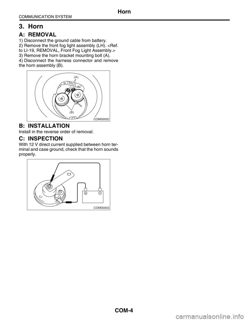
A: REMOVAL
1) Disconnect the ground cable from battery.
2) Remove the front fog light assembly (LH).
to LI-19, REMOVAL, Front Fog Light Assembly.>
3) Remove the horn bracket mounting bolt (A).
4) Disconnect the harness connector and remove
the horn assembly (B).
B: INSTALLATION
Install in the reverse order of removal.
C: INSPECTION
With 12 V direct current supplied between horn ter-
minal and case ground, check that the horn sounds
properly.
COM00002
(B)(A)
COM00003
Page 327 of 2870
COM-5
COMMUNICATION SYSTEM
Horn Switch
4. Horn Switch
A: REMOVAL
WARNING:
Before servicing, be sure to read the notes in
the AB section for proper handling of the driver
airbag module.
al Description.>
1) Disconnect the ground cable from battery.
2) Remove the driver’s airbag module.
14, Driver’s Airbag Module.>
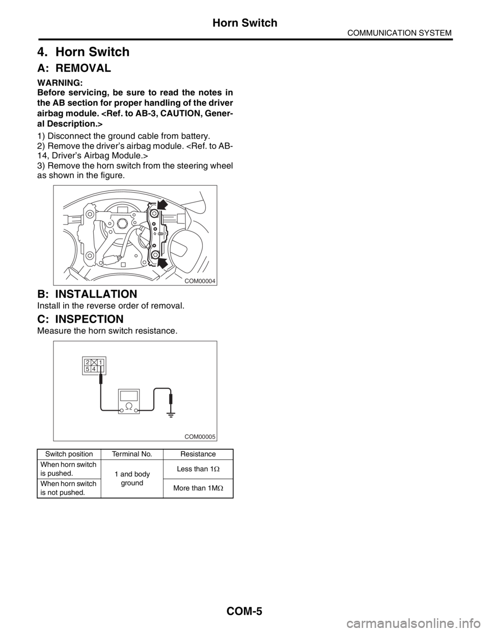
3) Remove the horn switch from the steering wheel
as shown in the figure.
B: INSTALLATION
Install in the reverse order of removal.
C: INSPECTION
Measure the horn switch resistance.
Switch position Terminal No. Resistance
When horn switch
is pushed.
1 and body
groundLess than 1Ω
When horn switch
is not pushed.More than 1MΩ
COM00004
2
5
4
COM00005
1
Page 328 of 2870
COM-6
COMMUNICATION SYSTEM
Horn Switch
Page 329 of 2870
FUJI HEAVY INDUSTRIES LTD. G8080GE7
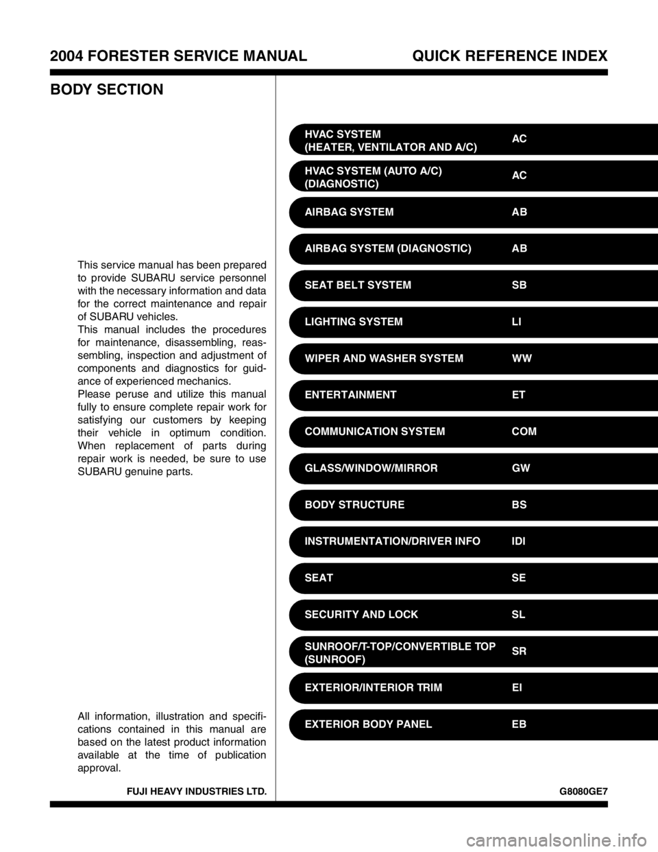
2004 FORESTER SERVICE MANUAL QUICK REFERENCE INDEX
BODY SECTION
This service manual has been prepared
to provide SUBARU service personnel
with the necessary information and data
for the correct maintenance and repair
of SUBARU vehicles.
This manual includes the procedures
for maintenance, disassembling, reas-
sembling, inspection and adjustment of
components and diagnostics for guid-
ance of experienced mechanics.
Please peruse and utilize this manual
fully to ensure complete repair work for
satisfying our customers by keeping
their vehicle in optimum condition.
When replacement of parts during
repair work is needed, be sure to use
SUBARU genuine parts.
All information, illustration and specifi-
cations contained in this manual are
based on the latest product information
available at the time of publication
approval.HVAC SYSTEM
(HEATER, VENTILATOR AND A/C)AC
HVAC SYSTEM (AUTO A/C)
(DIAGNOSTIC)AC
AIRBAG SYSTEM AB
AIRBAG SYSTEM (DIAGNOSTIC) AB
SEAT BELT SYSTEM SB
LIGHTING SYSTEM LI
WIPER AND WASHER SYSTEM WW
ENTERTAINMENT ET
COMMUNICATION SYSTEM COM
GLASS/WINDOW/MIRROR GW
BODY STRUCTURE BS
INSTRUMENTATION/DRIVER INFO IDI
SEAT SE
SECURITY AND LOCK SL
SUNROOF/T-TOP/CONVERTIBLE TOP
(SUNROOF)SR
EXTERIOR/INTERIOR TRIM EI
EXTERIOR BODY PANEL EB
Page 330 of 2870
2004 FORESTER SERVICE MANUAL QUICK REFERENCE INDEX
BODY SECTION
G8080GE7
CRUISE CONTROL SYSTEM CC
CRUISE CONTROL SYSTEM
(DIAGNOSTIC)CC(H4SO)
CRUISE CONTROL SYSTEM
(DIAGNOSTIC)CC(H4DOTC)
CRUISE CONTROL SYSTEM
(DIAGNOSTIC)CC(H4DOTC 2.5)
IMMOBILIZER (DIAGNOSTIC) IM
Trending: camshaft, cam sprocket, flat tire, OBD port, oil viscosity, maintenance, jack points

