SUBARU FORESTER 2004 Service Repair Manual
FORESTER 2004
SUBARU
SUBARU
https://www.carmanualsonline.info/img/17/57426/w960_57426-0.png
SUBARU FORESTER 2004 Service Repair Manual
Trending: turn signal bulb, fuel filter location, brake pads replacement, wiper fluid, power steering, tire type, four wheel drive
Page 331 of 2870

GLASS/WINDOW/MIRROR
GW
Page
1. General Description ....................................................................................2
2. Power Window System ...............................................................................6
3. Power Window Control Switch ....................................................................7
4. Remote Control Mirror System..................................................................10
5. Scalp Cap..................................................................................................11
6. Outer Mirror Assembly ..............................................................................12
7. Outer Mirror ...............................................................................................14
8. Remote Control Mirror Switch ...................................................................15
9. Front Door Glass .......................................................................................17
10. Front Regulator and Motor Assembly .......................................................21
11. Rear Door Glass .......................................................................................22
12. Rear Regulator and Motor Assembly ........................................................24
13. Windshield Glass ......................................................................................25
14. Inner Rearview Mirror................................................................................28
15. Rear Gate Glass .......................................................................................29
16. Rear Window Defogger System ................................................................30
17. Rear Window Defogger .............................................................................31
18. Rear Quarter Glass ...................................................................................32
19. Roof Window Glass...................................................................................34
Page 332 of 2870
GW-2
GLASS/WINDOW/MIRROR
General Description
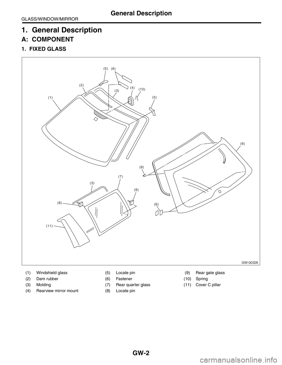
1. General Description
A: COMPONENT
1. FIXED GLASS
(1) Windshield glass (5) Locate pin (9) Rear gate glass
(2) Dam rubber (6) Fastener (10) Spring
(3) Molding (7) Rear quarter glass (11) Cover C pillar
(4) Rearview mirror mount (8) Locate pin
GW-00326
(1)(2)
(3) (6)
(4)
(10)
(9)
(6) (8)
(7)
(3)
(11)(8)
(8)
(5)
(5)
Page 333 of 2870
GW-3
GLASS/WINDOW/MIRROR
General Description
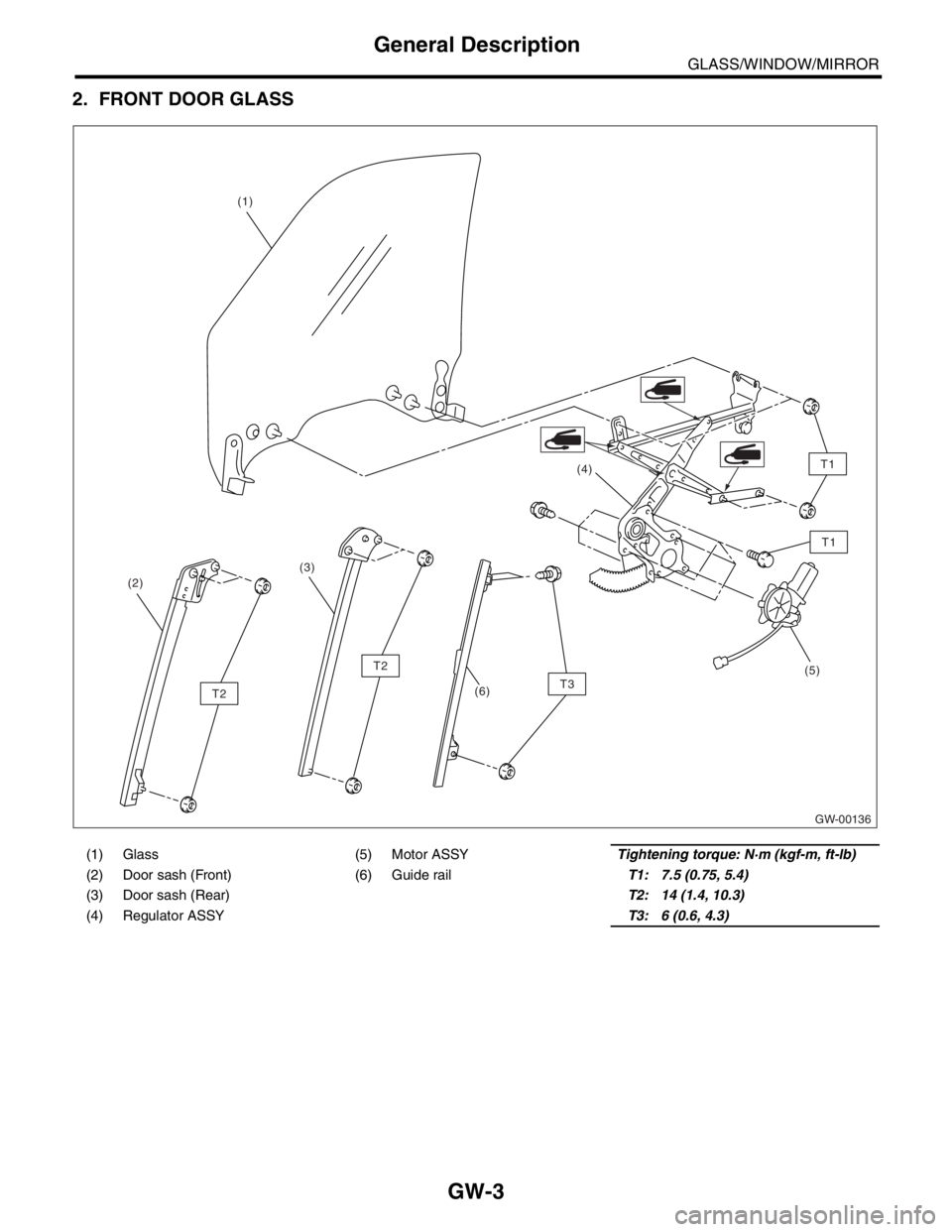
2. FRONT DOOR GLASS
(1) Glass (5) Motor ASSY Tightening torque: N·m (kgf-m, ft-lb)
(2) Door sash (Front) (6) Guide rail T1: 7.5 (0.75, 5.4)
(3) Door sash (Rear) T2: 14 (1.4, 10.3)
(4) Regulator ASSYT3: 6 (0.6, 4.3)
GW-00136
(1)
(2)(4)
(5)
T2
T2
T1
T1
(3)
(6)T3
Page 334 of 2870
GW-4
GLASS/WINDOW/MIRROR
General Description
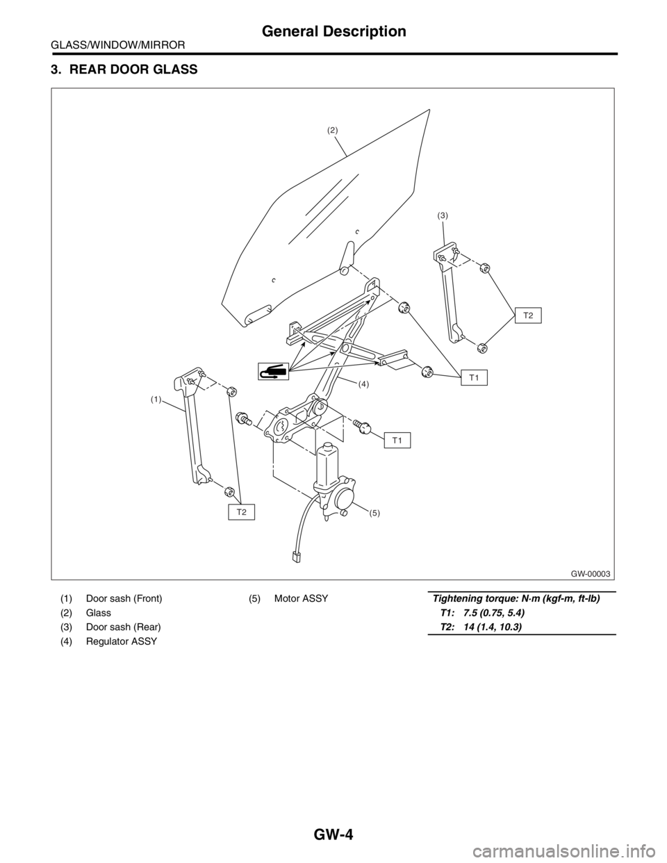
3. REAR DOOR GLASS
(1) Door sash (Front) (5) Motor ASSYTightening torque: N·m (kgf-m, ft-lb)
(2) GlassT1: 7.5 (0.75, 5.4)
(3) Door sash (Rear) T2: 14 (1.4, 10.3)
(4) Regulator ASSY
GW-00003
(1)(2)
(3)
(4)
(5)
T2
T2
T1
T1
Page 335 of 2870
GW-5
GLASS/WINDOW/MIRROR
General Description
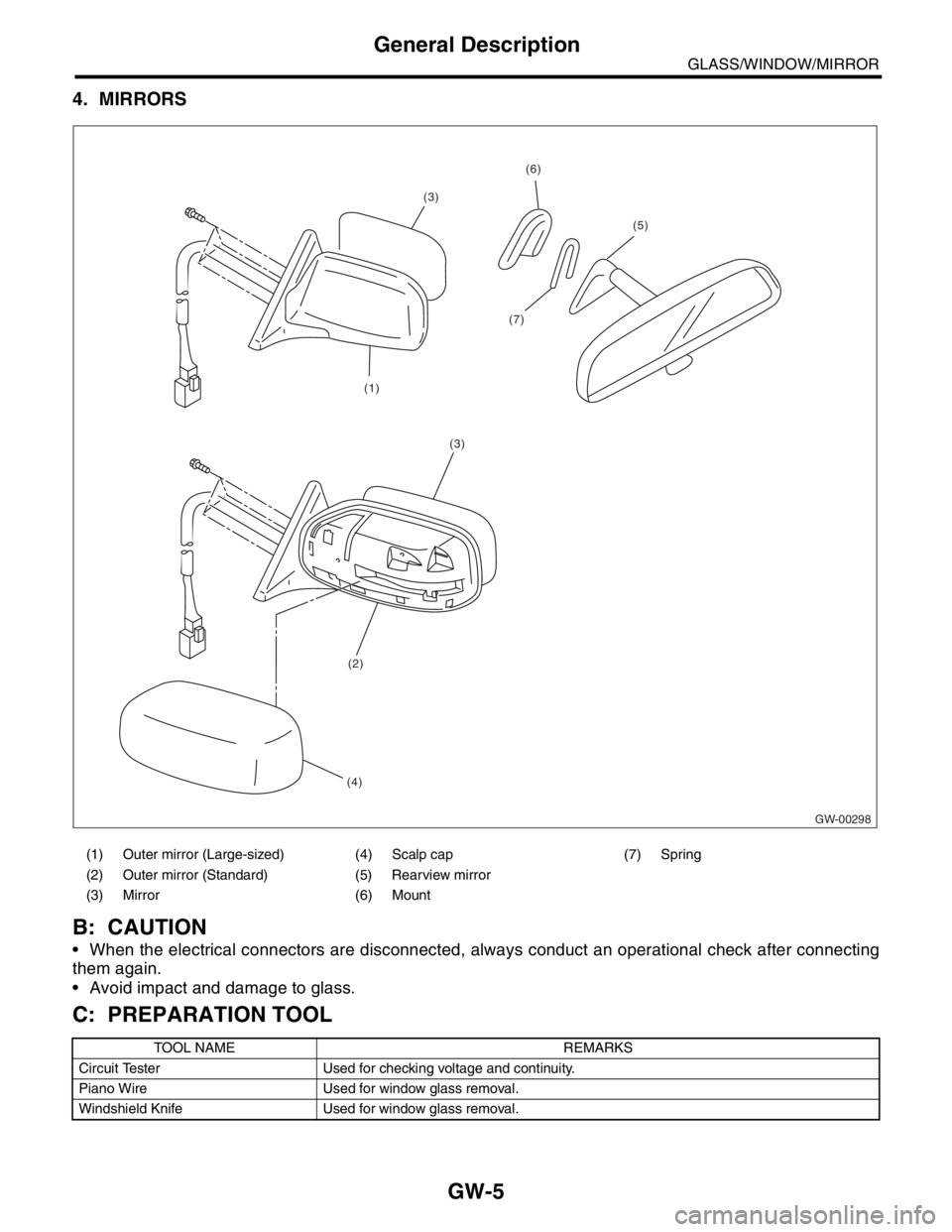
4. MIRRORS
B: CAUTION
When the electrical connectors are disconnected, always conduct an operational check after connecting
them again.
Avoid impact and damage to glass.
C: PREPARATION TOOL
(1) Outer mirror (Large-sized) (4) Scalp cap (7) Spring
(2) Outer mirror (Standard) (5) Rearview mirror
(3) Mirror (6) Mount
TOOL NAME REMARKS
Circuit Tester Used for checking voltage and continuity.
Piano Wire Used for window glass removal.
Windshield Knife Used for window glass removal.
GW-00298
(1)
(7)
(3)
(5)
(6)
(3)
(2)
(4)
Page 336 of 2870
GW-6
GLASS/WINDOW/MIRROR
Power Window System
2. Power Window System
A: WIRING DIAGRAM
1. POWER WINDOW
B: INSPECTION
Symptom Repair order
All power windows does not operate.(1) Fuse (SBF-6) (F/B No. 18)
(2) Power window circuit breaker
(3) Power window relay
(4) Wire harness
One window does not operate.(1) Power window main switch
(2) Power window sub switch
(3) Power window motor
(4) Wire harness
“Window Lock” does not operate. Power window main switch
Page 337 of 2870
GW-7
GLASS/WINDOW/MIRROR
Power Window Control Switch
3. Power Window Control
Switch
A: REMOVAL
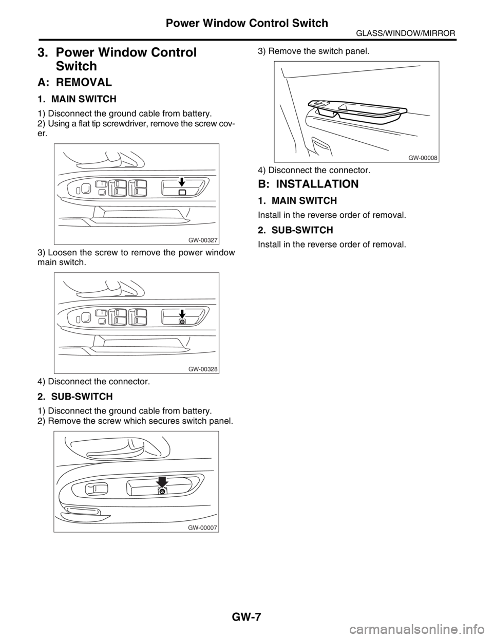
1. MAIN SWITCH
1) Disconnect the ground cable from battery.
2) Using a flat tip screwdriver, remove the screw cov-
er.
3) Loosen the screw to remove the power window
main switch.
4) Disconnect the connector.
2. SUB-SWITCH
1) Disconnect the ground cable from battery.
2) Remove the screw which secures switch panel.3) Remove the switch panel.
4) Disconnect the connector.
B: INSTALLATION
1. MAIN SWITCH
Install in the reverse order of removal.
2. SUB-SWITCH
Install in the reverse order of removal.GW-00327
GW-00328
GW-00007
GW-00008
Page 338 of 2870
GW-8
GLASS/WINDOW/MIRROR
Power Window Control Switch
C: INSPECTION
1. MAIN SWITCH
Measure the switch resistance.
LHD model
If NG, replace the main switch.
Switch position Terminal No. Standard
Driver’s sideAUTO UP 13 and 2, 1 and 5 Less than 1 Ω
UP 13 and 2, 1 and 5 Less than 1 Ω
OFF1 and 2
1 and 5
2 and 5Less than 1 Ω
DOWN 13 and 1, 2 and 5 Less than 1 Ω
AUTO DOWN 13 and 1, 2 and 5 Less than 1 Ω
Front passenger’s sideUP 13 and 7, 6 and 5 Less than 1 Ω
OFF5 and 6
5 and 7
6 and 7Less than 1 Ω
DOWN 13 and 6, 7 and 5 Less than 1 Ω
Rear LHUP 10 and 13, 11 and 5 Less than 1 Ω
OFF5 and 11
5 and 10
11 and 10Less than 1 Ω
DOWN 13 and 11, 10 and 5 Less than 1 Ω
Rear RHUP 13 and 15, 16 and 5 Less than 1 Ω
OFF5 and 15
5 and 16
15 and 16Less than 1 Ω
DOWN 13 and 16, 15 and 5 Less than 1 Ω
Page 339 of 2870

GW-9
GLASS/WINDOW/MIRROR
Power Window Control Switch
RHD model
If NG, replace the main switch.
2. SUB-SWITCH
Measure the switch resistance.
If NG, replace the sub-switch.
Switch position Terminal No. Standard
Driver’s sideAUTO UP 12 and 7, 6 and 1 Less than 1 Ω
UP 12 and 7, 6 and 1 Less than 1 Ω
OFF1 and 6
1 and 7
6 and 7Less than 1 Ω
DOWN 12 and 6, 7 and 1 Less than 1 Ω
AUTO DOWN 12 and 6, 7 and 1 Less than 1 Ω
Front passenger’s sideUP 12 and 2, 3 and 1 Less than 1 Ω
OFF1 and 2
1 and 3
2 and 3Less than 1 Ω
DOWN 12 and 3, 2 and 1 Less than 1 Ω
Rear LHUP 12 and 10, 9 and 1 Less than 1 Ω
OFF1 and 9
1 and 10
9 and 10Less than 1 Ω
DOWN 12 and 9, 10 and 1 Less than 1 Ω
Rear RHUP 12 and 14, 13 and 1 Less than 1 Ω
OFF1 and 13
1 and 14
13 and 14Less than 1 Ω
DOWN 12 and 13, 14 and 1 Less than 1 Ω
Switch position Terminal No. Standard
Front passenger’s side
and rearUP8 and 5, 6 and 7, 1 and 8, 1 and
5Less than 1 Ω
OFF 4 and 5, 6 and 7 Less than 1 Ω
DOWN8 and 7, 4 and 5, 1 and 8, 1 and
7Less than 1 Ω
Page 340 of 2870
GW-10
GLASS/WINDOW/MIRROR
Remote Control Mirror System
4. Remote Control Mirror System
A: WIRING DIAGRAM
1. REMOTE CONTROL MIRROR
B: INSPECTION
Symptom Repair order
All function does not operate.(1) Fuse (F/B No. 4) (F/B No. 13) (F/B No. 17) (F/B No. 18)
(2) Mirror switch
(3) Wiring harness
One side of the mirror motor does not operate.(1) Mirror switch
(2) Mirror motor
(3) Wiring harness
Heated mirror does not operate.(1) Mirror switch
(2) Heated mirror
(3) Wiring harness
Trending: power steering pump, camshaft, brake pads, fuel tank capacity, refrigerant type, seats, sensor

