SUBARU FORESTER 2004 Service Repair Manual
FORESTER 2004
SUBARU
SUBARU
https://www.carmanualsonline.info/img/17/57426/w960_57426-0.png
SUBARU FORESTER 2004 Service Repair Manual
Trending: wheel bolts, brake, brakes, radiator cap, headlight bulb, air conditioning, diagram
Page 291 of 2870
WW-3
WIPER AND WASHER SYSTEM
General Description
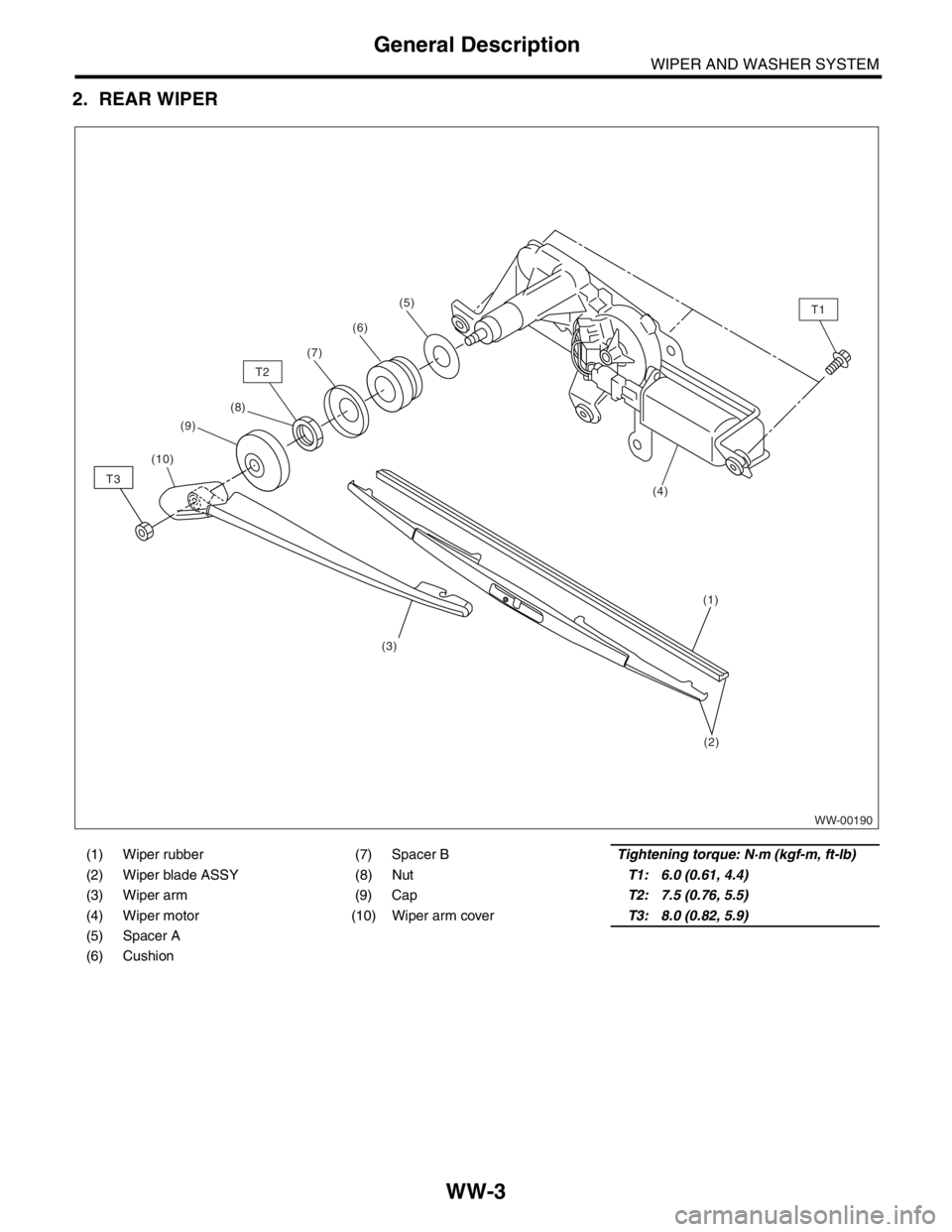
2. REAR WIPER
(1) Wiper rubber (7) Spacer BTightening torque: N·m (kgf-m, ft-lb)
(2) Wiper blade ASSY (8) NutT1: 6.0 (0.61, 4.4)
(3) Wiper arm (9) CapT2: 7.5 (0.76, 5.5)
(4) Wiper motor (10) Wiper arm coverT3: 8.0 (0.82, 5.9)
(5) Spacer A
(6) Cushion
WW-00190
T1(5)
(1)
T2
T3
(2)
(6)
(7)
(9)
(3) (8)
(4)
(10)
Page 292 of 2870
WW-4
WIPER AND WASHER SYSTEM
General Description
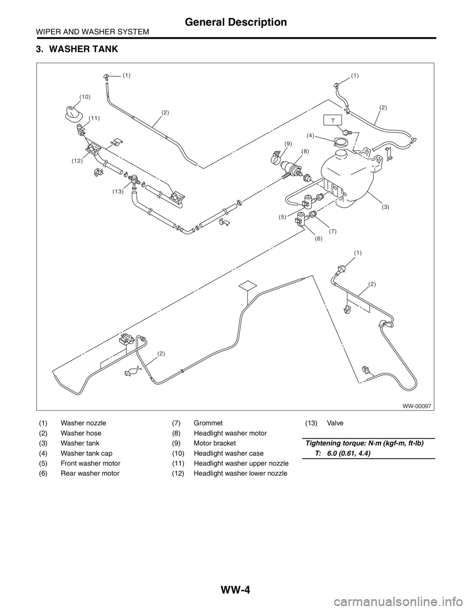
3. WASHER TANK
(1) Washer nozzle (7) Grommet (13) Valve
(2) Washer hose (8) Headlight washer motor
(3) Washer tank (9) Motor bracketTightening torque: N·m (kgf-m, ft-lb)
(4) Washer tank cap (10) Headlight washer caseT: 6.0 (0.61, 4.4)
(5) Front washer motor (11) Headlight washer upper nozzle
(6) Rear washer motor (12) Headlight washer lower nozzle
WW-00097
(1) (1)
(1)(2)
(2) (10)
(11)
(12)
(13)
(2)
(2)(8)
(7)
(6) (5)(9)
T
(3)
(4)
Page 293 of 2870
WW-5
WIPER AND WASHER SYSTEM
General Description
C: CAUTION
Reconnect the connectors and hoses securely.
After reconnecting, confirm that each function oper-
ates normally.
Be careful that wiring harnesses of airbag sys-
tem pass near electrical parts and switches.
Wiring harnesses and connectors of all airbag
system are yellow color. Do not use a tester on
these circuits.
Care must be taken when installing the piping
hose so that no bending, jamming, etc. are caused.
If even a little oil or grease such as silicon oil gets
in the tank and washer passages, an oil film easily
forms on the glass, causing the wiper to chatter and
judder. Therefore, be careful not to let this happen.
Page 294 of 2870
WW-6
WIPER AND WASHER SYSTEM
Wiper and Washer System
2. Wiper and Washer System
A: WIRING DIAGRAM
1. WIPER AND WASHER (FRONT)
2. WIPER AND WASHER (REAR)
B: INSPECTION
Symptom Repair order
Wiper and washers do not operate. (1) Wiper fuse (F/B No. 14, 15)
(2) Combination switch
(3) Wiper motor
(4) Wiring harness
Wipers do not operate in LO or HI. (1) Combination switch
(2) Wiper motor
(3) Wiring harness
Wipers do not operate in INT. (1) Combination switch
(2) Wiper motor
(3) Wiring harness
Washer motor does not operate. (1) Washer switch
(2) Washer motor
(3) Wiring harness
Wipers do not operate when washer switch is ON. (1) Washer motor
(2) Wiring harness
Washer fluid spray does not operate. (1) Washer motor
(2) Washer hose and nozzle
Page 295 of 2870
WW-7
WIPER AND WASHER SYSTEM
Combination Switch (Wiper)
3. Combination Switch (Wiper)
A: REMOVAL
1) Loosen the screw to remove the steering column
cover.
2) Disconnect the connectors from combination
switches.
3) Loosen the screw to remove combination switch.
B: INSTALLATION
Install in the reverse order of removal.
C: INSPECTION
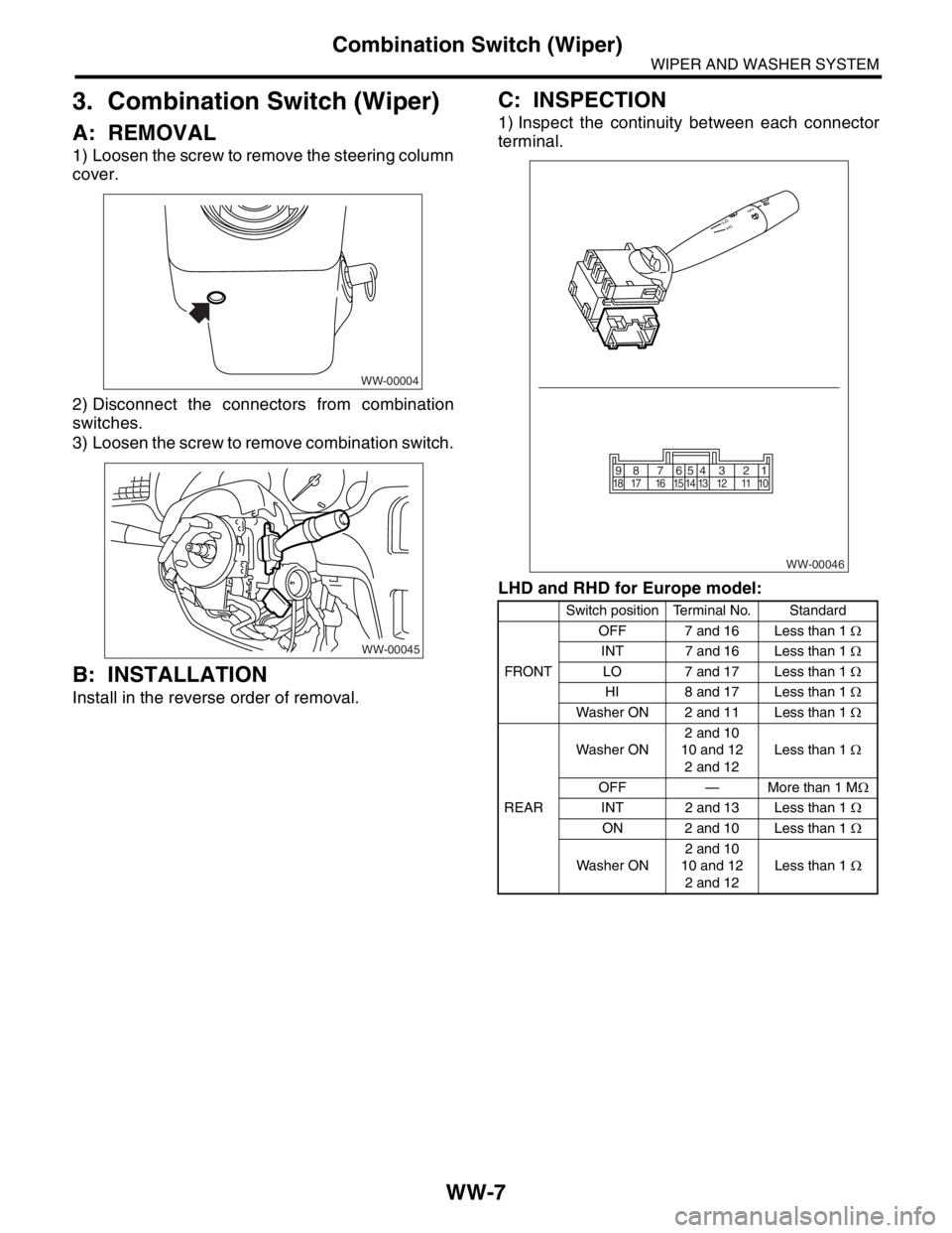
1) Inspect the continuity between each connector
terminal.
LHD and RHD for Europe model:
WW-00004
WW-00045
Switch position Terminal No. Standard
FRONTOFF 7 and 16 Less than 1 Ω
INT 7 and 16 Less than 1 Ω
LO 7 and 17 Less than 1 Ω
HI 8 and 17 Less than 1 Ω
Washer ON 2 and 11 Less than 1 Ω
REARWasher ON2 and 10
10 and 12
2 and 12Less than 1 Ω
OFF — More than 1 MΩ
INT 2 and 13 Less than 1 Ω
ON 2 and 10 Less than 1 Ω
Washer ON2 and 10
10 and 12
2 and 12Less than 1 Ω
WW-00046
87654321 917 16 15 14 13 12 11 10 18
Page 296 of 2870
WW-8
WIPER AND WASHER SYSTEM
Combination Switch (Wiper)
RHD except for Europe model:
2) If continuity is not as specified, replace the switch.
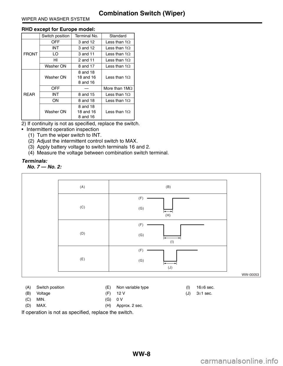
Intermittent operation inspection
(1) Turn the wiper switch to INT.
(2) Adjust the intermittent control switch to MAX.
(3) Apply battery voltage to switch terminals 16 and 2.
(4) Measure the voltage between combination switch terminal.
Terminals:
No. 7 — No. 2:
If operation is not as specified, replace the switch.
Switch position Terminal No. Standard
FRONTOFF 3 and 12 Less than 1Ω
INT 3 and 12 Less than 1Ω
LO 3 and 11 Less than 1Ω
HI 2 and 11 Less than 1Ω
Washer ON 8 and 17 Less than 1Ω
REARWasher ON8 and 18
18 and 16
8 and 16Less than 1Ω
OFF — More than 1MΩ
INT 8 and 15 Less than 1Ω
ON 8 and 18 Less than 1Ω
Washer ON8 and 18
18 and 16
8 and 16Less than 1Ω
WW-00053 (A) (B)
(C)
(H)
(I)
(J) (D)
(F)
(G) (F)
(G) (F)
(G)
(E)
(A) Switch position (E) Non variable type (I) 16±6 sec.
(B) Voltage (F) 12 V (J) 3±1 sec.
(C) MIN. (G) 0 V
(D) MAX. (H) Approx. 2 sec.
Page 297 of 2870
WW-9
WIPER AND WASHER SYSTEM
Wiper Blade
4. Wiper Blade
A: REMOVAL
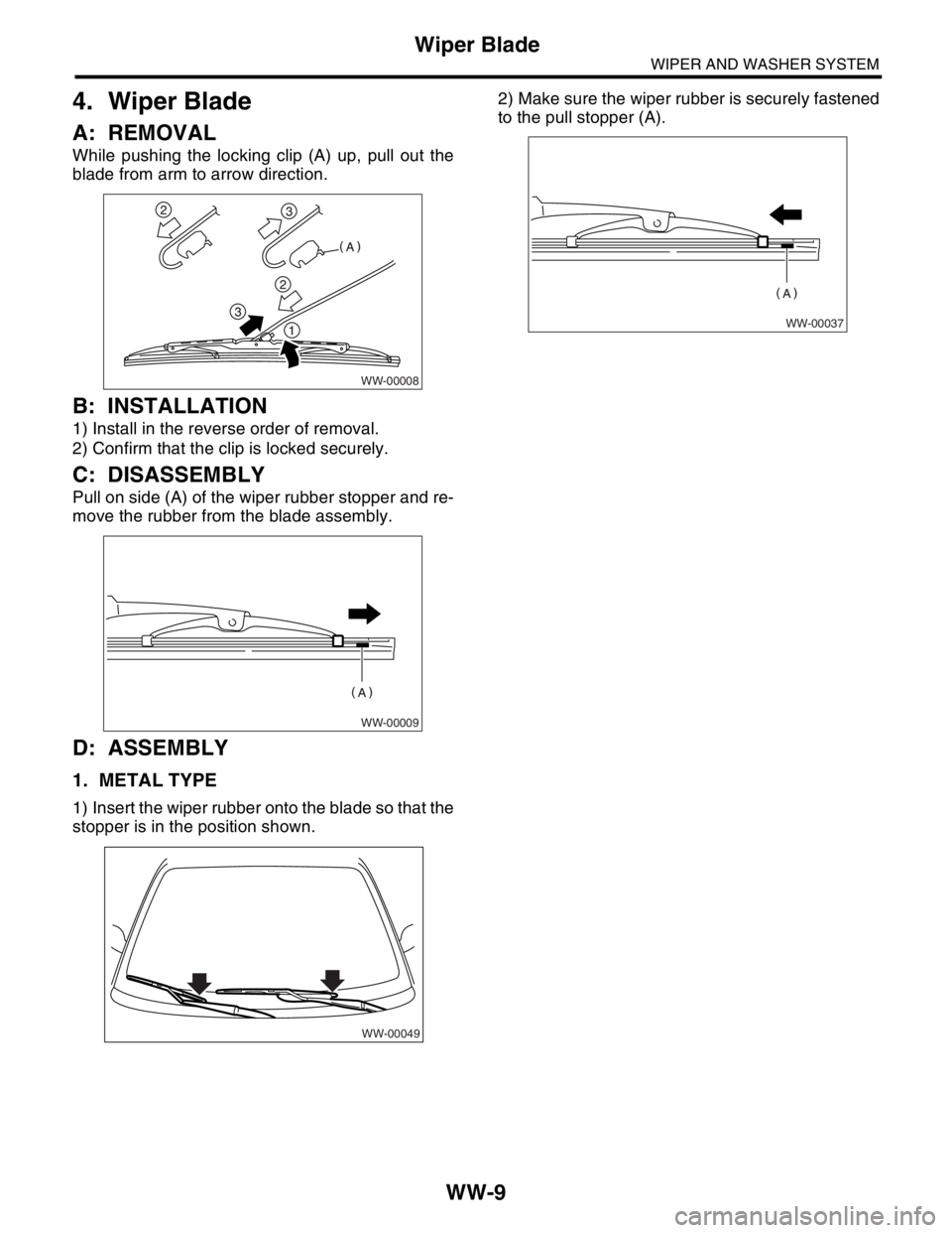
While pushing the locking clip (A) up, pull out the
blade from arm to arrow direction.
B: INSTALLATION
1) Install in the reverse order of removal.
2) Confirm that the clip is locked securely.
C: DISASSEMBLY
Pull on side (A) of the wiper rubber stopper and re-
move the rubber from the blade assembly.
D: ASSEMBLY
1. METAL TYPE
1) Insert the wiper rubber onto the blade so that the
stopper is in the position shown.2) Make sure the wiper rubber is securely fastened
to the pull stopper (A).
WW-00008
WW-00009
WW-00049
WW-00037
Page 298 of 2870
WW-10
WIPER AND WASHER SYSTEM
Wiper Blade
2. RESIN TYPE
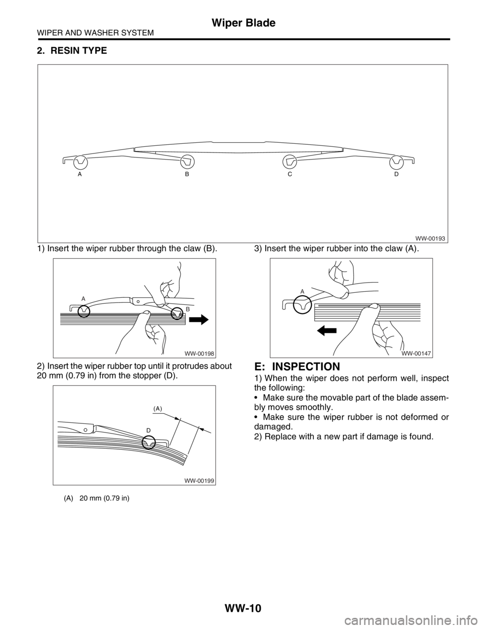
1) Insert the wiper rubber through the claw (B).
2) Insert the wiper rubber top until it protrudes about
20 mm (0.79 in) from the stopper (D).3) Insert the wiper rubber into the claw (A).
E: INSPECTION
1) When the wiper does not perform well, inspect
the following:
Make sure the movable part of the blade assem-
bly moves smoothly.
Make sure the wiper rubber is not deformed or
damaged.
2) Replace with a new part if damage is found.
WW-00193 ABCD
(A) 20 mm (0.79 in)
WW-00198
A
B
WW-00199
D (A)
A
WW-00147
Page 299 of 2870
WW-11
WIPER AND WASHER SYSTEM
Washer Tank and Motor
5. Washer Tank and Motor
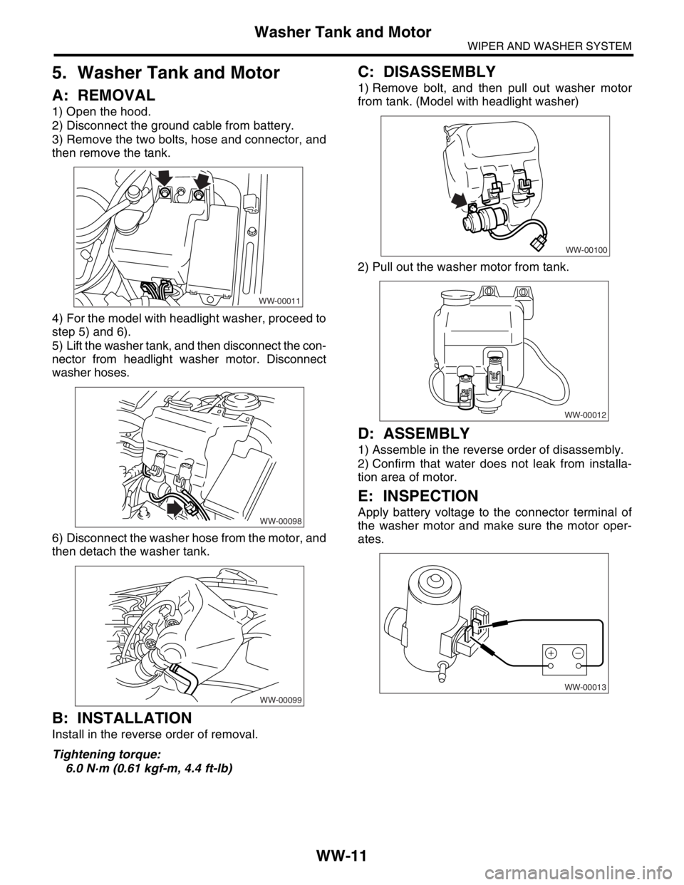
A: REMOVAL
1) Open the hood.
2) Disconnect the ground cable from battery.
3) Remove the two bolts, hose and connector, and
then remove the tank.
4) For the model with headlight washer, proceed to
step 5) and 6).
5) Lift the washer tank, and then disconnect the con-
nector from headlight washer motor. Disconnect
washer hoses.
6) Disconnect the washer hose from the motor, and
then detach the washer tank.
B: INSTALLATION
Install in the reverse order of removal.
Tightening torque:
6.0 N·m (0.61 kgf-m, 4.4 ft-lb)
C: DISASSEMBLY
1) Remove bolt, and then pull out washer motor
from tank. (Model with headlight washer)
2) Pull out the washer motor from tank.
D: ASSEMBLY
1) Assemble in the reverse order of disassembly.
2) Confirm that water does not leak from installa-
tion area of motor.
E: INSPECTION
Apply battery voltage to the connector terminal of
the washer motor and make sure the motor oper-
ates.
WW-00011
WW-00098
WW-00099
WW-00100
WW-00012
WW-00013
Page 300 of 2870
WW-12
WIPER AND WASHER SYSTEM
Front Wiper Arm
6. Front Wiper Arm
A: REMOVAL
1) Open the hood.
2) Remove the cap.
3) Loosen the nut to remove arm.
B: INSTALLATION
1) Install in the reverse order of removal.
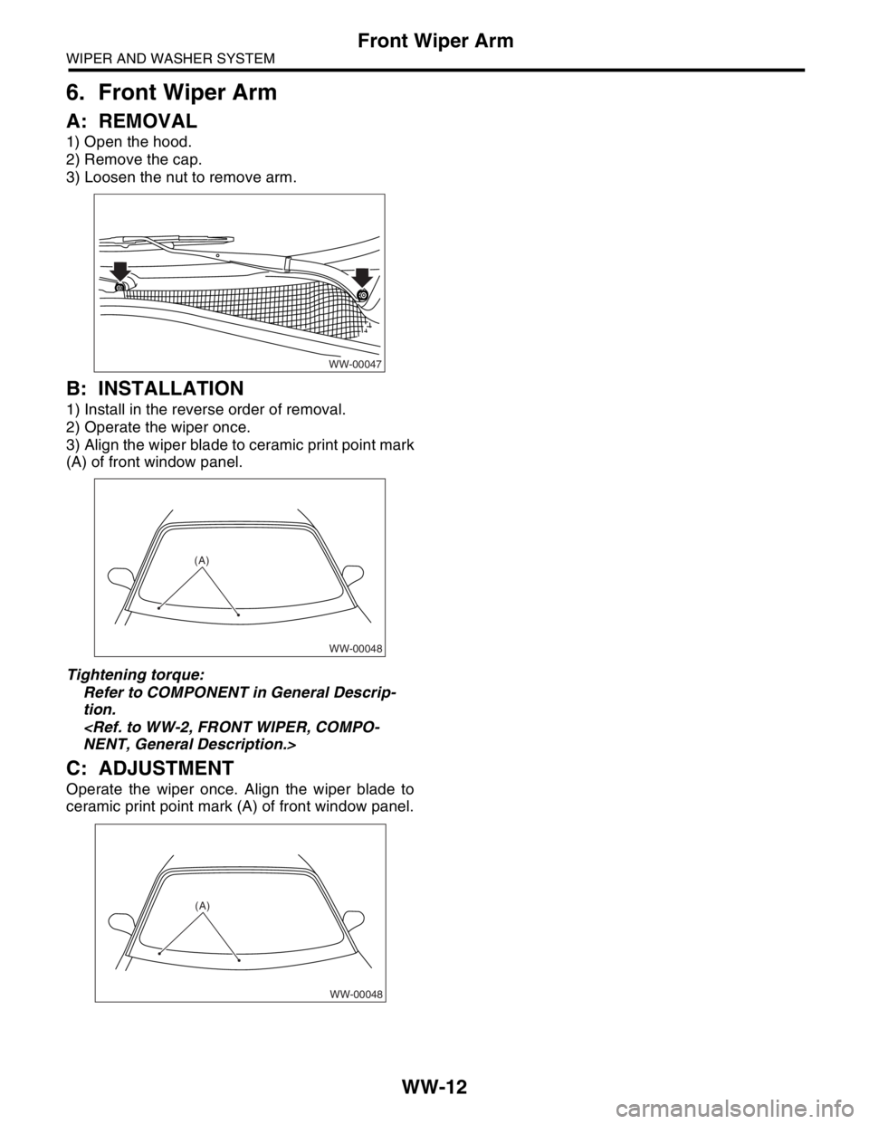
2) Operate the wiper once.
3) Align the wiper blade to ceramic print point mark
(A) of front window panel.
Tightening torque:
Refer to COMPONENT in General Descrip-
tion.
NENT, General Description.>
C: ADJUSTMENT
Operate the wiper once. Align the wiper blade to
ceramic print point mark (A) of front window panel.
WW-00047
WW-00048
(A)
WW-00048
(A)
Trending: ABS, coolant temperature, jump cable, ESP inoperative, brake, ECO mode, low beam
