SUBARU FORESTER 2004 Service Repair Manual
FORESTER 2004
SUBARU
SUBARU
https://www.carmanualsonline.info/img/17/57426/w960_57426-0.png
SUBARU FORESTER 2004 Service Repair Manual
Trending: warning lights, jump cable, check engine, fuel tank removal, refrigerant type, cam sprocket wrench, battery
Page 311 of 2870
ENTERTAINMENT
ET
Page
1. General Description ....................................................................................2
2. Radio System ..............................................................................................3
3. Front Accessory Power Supply Socket System ..........................................4
4. Radio Body..................................................................................................5
5. Front Speaker .............................................................................................6
6. Antenna .......................................................................................................7
7. Antenna Amplifier ........................................................................................8
8. Front Accessory Power Supply Socket .......................................................9
Page 312 of 2870
ET-2
ENTERTAINMENT
General Description
1. General Description
A: CAUTION
Before disassembling or reassembling parts, al-
ways disconnect the battery ground cable. When re-
placing radio, control module and other parts
provided with memory functions, record memory con-
tents before disconnecting the battery ground cable.
Otherwise, the memory will be erased.
Reassemble in reverse order of disassembly, un-
less otherwise indicated.
Adjust parts to the given specifications.
Connect the connectors and hoses securely dur-
ing reassembly.
After reassembly, make sure functional parts op-
erate smoothly.
B: PREPARATION TOOL
1. GENERAL TOOL
TOOL NAME REMARKS
Circuit tester Used for measuring resis-
tance and voltage.
Conductive silver composi-
tion
(DUPONT No. 4817 or
equivalent)Used for repairing antenna
wire.
Page 313 of 2870
ET-3
ENTERTAINMENT
Radio System
2. Radio System
A: WIRING DIAGRAM
1. RADIO
B: INSPECTION
Symptom Repair order
No power coming in. (No display and no sound from speakers.) (1) Check the fuse and power supply for radio.
(2) Check the radio ground.
(3) Remove the radio for repair.
A specific speaker does not operate. (1) Check the speaker.
(2) Check the output circuit between radio and speaker.
Radio generates noise with engine running. (1) Check the radio ground.
(2) Check the generator.
(3) Check the ignition coil.
(4) Remove the radio for repair.
AM and FM modes are weak or noisy. (1) Check the antenna.
(2) Check the antenna amplifier.
(3) Check the noise suppressor.
(4) Check the radio ground.
(5) Remove the radio for repair.
Page 314 of 2870
ET-4
ENTERTAINMENT
Front Accessory Power Supply Socket System
3. Front Accessory Power Sup-
ply Socket System
A: WIRING DIAGRAM
1. FRONT ACCESSORY POWER SUPPLY
SOCKET SYSTEM
sory Power Supply System.>
Page 315 of 2870
ET-5
ENTERTAINMENT
Radio Body
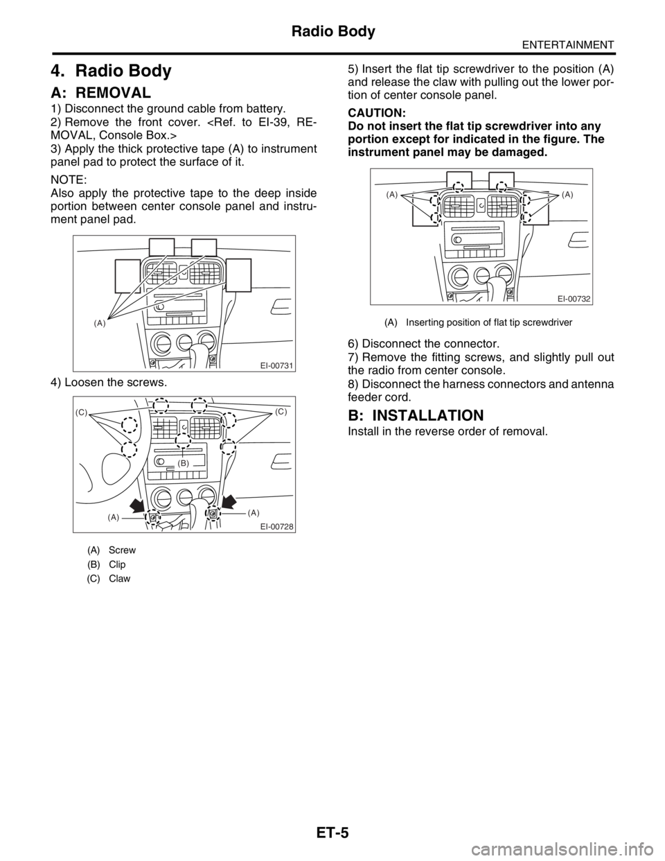
4. Radio Body
A: REMOVAL
1) Disconnect the ground cable from battery.
2) Remove the front cover.
MOVAL, Console Box.>
3) Apply the thick protective tape (A) to instrument
panel pad to protect the surface of it.
NOTE:
Also apply the protective tape to the deep inside
portion between center console panel and instru-
ment panel pad.
4) Loosen the screws.5) Insert the flat tip screwdriver to the position (A)
and release the claw with pulling out the lower por-
tion of center console panel.
CAUTION:
Do not insert the flat tip screwdriver into any
portion except for indicated in the figure. The
instrument panel may be damaged.
6) Disconnect the connector.
7) Remove the fitting screws, and slightly pull out
the radio from center console.
8) Disconnect the harness connectors and antenna
feeder cord.
B: INSTALLATION
Install in the reverse order of removal.
(A) Screw
(B) Clip
(C) Claw
EI-00731
(A)
EI-00728
(C)
(A)(A)(C)
(B)
(A) Inserting position of flat tip screwdriver
EI-00732
(A) (A)
Page 316 of 2870
ET-6
ENTERTAINMENT
Front Speaker
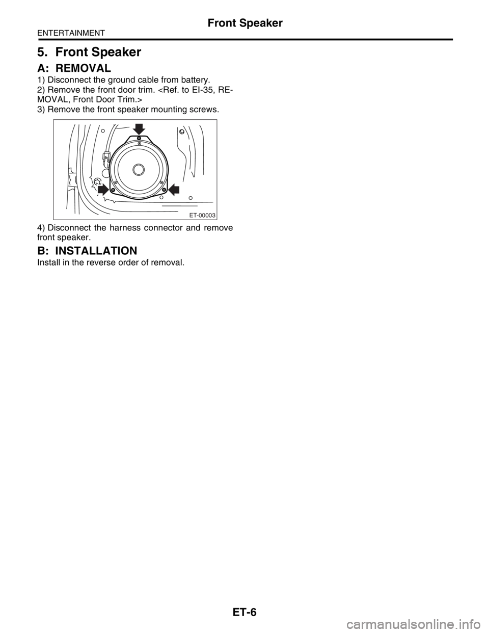
5. Front Speaker
A: REMOVAL
1) Disconnect the ground cable from battery.
2) Remove the front door trim.
MOVAL, Front Door Trim.>
3) Remove the front speaker mounting screws.
4) Disconnect the harness connector and remove
front speaker.
B: INSTALLATION
Install in the reverse order of removal.
ET-00003
Page 317 of 2870
ET-7
ENTERTAINMENT
Antenna
6. Antenna
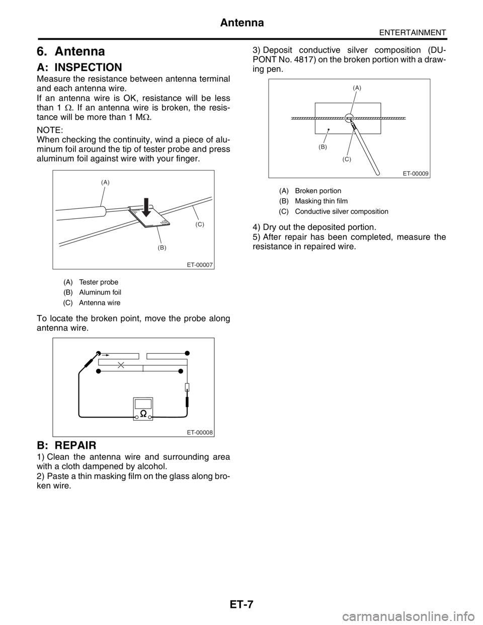
A: INSPECTION
Measure the resistance between antenna terminal
and each antenna wire.
If an antenna wire is OK, resistance will be less
than 1 Ω. If an antenna wire is broken, the resis-
tance will be more than 1 MΩ.
NOTE:
When checking the continuity, wind a piece of alu-
minum foil around the tip of tester probe and press
aluminum foil against wire with your finger.
To locate the broken point, move the probe along
antenna wire.
B: REPAIR
1) Clean the antenna wire and surrounding area
with a cloth dampened by alcohol.
2) Paste a thin masking film on the glass along bro-
ken wire.3) Deposit conductive silver composition (DU-
PONT No. 4817) on the broken portion with a draw-
ing pen.
4) Dry out the deposited portion.
5) After repair has been completed, measure the
resistance in repaired wire.
(A) Tester probe
(B) Aluminum foil
(C) Antenna wire
ET-00007
(B)(C) (A)
ET-00008
(A) Broken portion
(B) Masking thin film
(C) Conductive silver composition
(B)
(C)
ET-00009
(A)
Page 318 of 2870
ET-8
ENTERTAINMENT
Antenna Amplifier
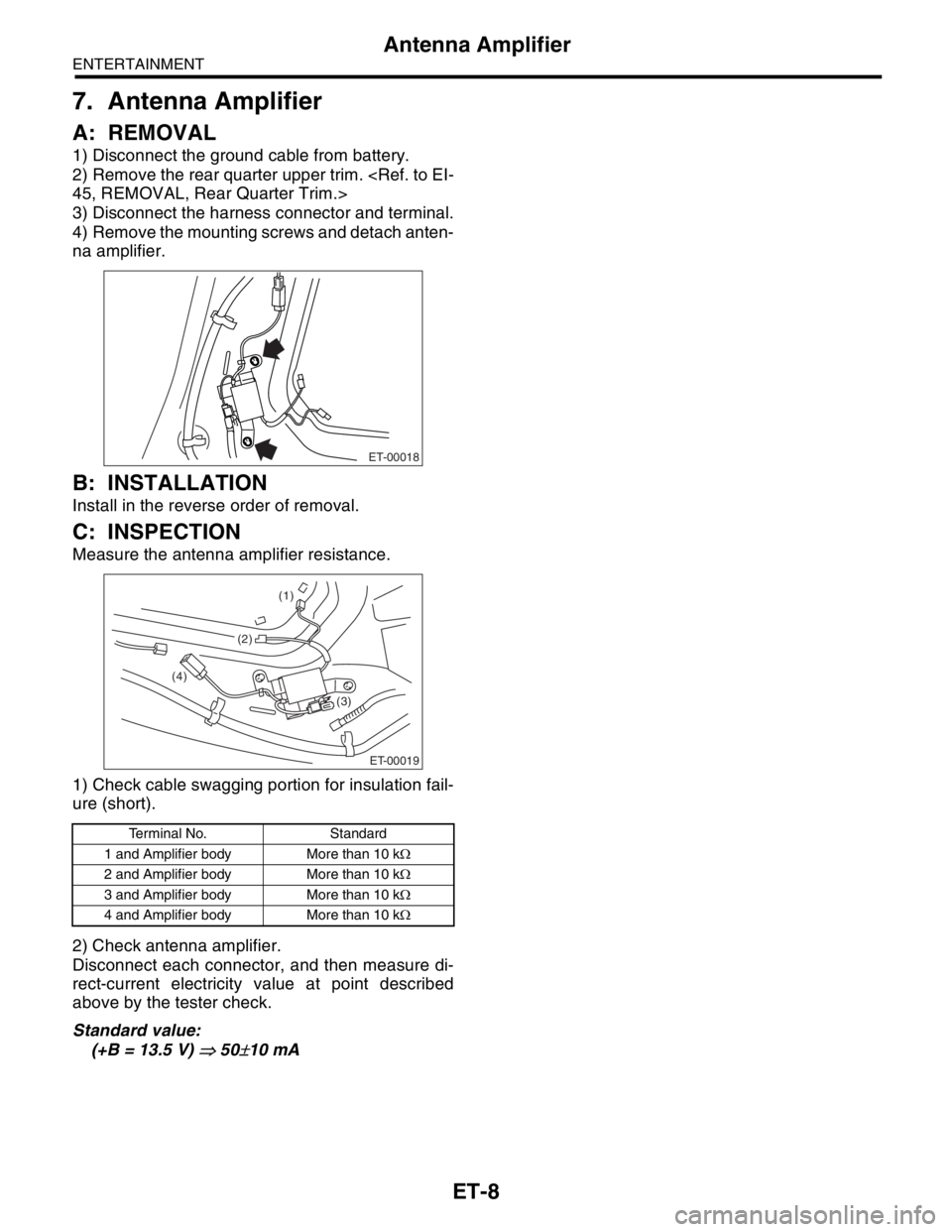
7. Antenna Amplifier
A: REMOVAL
1) Disconnect the ground cable from battery.
2) Remove the rear quarter upper trim.
45, REMOVAL, Rear Quarter Trim.>
3) Disconnect the harness connector and terminal.
4) Remove the mounting screws and detach anten-
na amplifier.
B: INSTALLATION
Install in the reverse order of removal.
C: INSPECTION
Measure the antenna amplifier resistance.
1) Check cable swagging portion for insulation fail-
ure (short).
2) Check antenna amplifier.
Disconnect each connector, and then measure di-
rect-current electricity value at point described
above by the tester check.
Standard value:
(+B = 13.5 V)
⇒ 50±10 mA
Terminal No. Standard
1 and Amplifier body More than 10 kΩ
2 and Amplifier body More than 10 kΩ
3 and Amplifier body More than 10 kΩ
4 and Amplifier body More than 10 kΩ
ET-00018
ET-00019
(3) (4)
(1)
(2)
Page 319 of 2870
ET-9
ENTERTAINMENT
Front Accessory Power Supply Socket
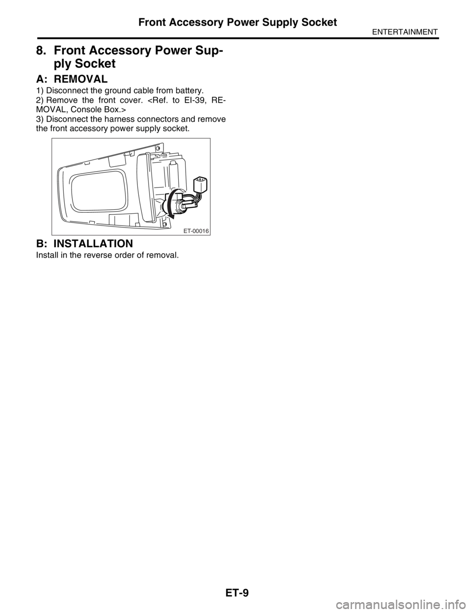
8. Front Accessory Power Sup-
ply Socket
A: REMOVAL
1) Disconnect the ground cable from battery.
2) Remove the front cover.
MOVAL, Console Box.>
3) Disconnect the harness connectors and remove
the front accessory power supply socket.
B: INSTALLATION
Install in the reverse order of removal.
ET-00016
Page 320 of 2870
ET-10
ENTERTAINMENT
Front Accessory Power Supply Socket
Trending: oil viscosity, coolant capacity, jacking, sensor, dimensions, door lock, timing belt


