SUBARU FORESTER 2004 Service Manual Online
Manufacturer: SUBARU, Model Year: 2004, Model line: FORESTER, Model: SUBARU FORESTER 2004Pages: 2870, PDF Size: 38.67 MB
Page 81 of 2870

AC-25
HVAC SYSTEM (AUTO A/C)(DIAGNOSTIC)
Diagnostic Procedure for Actuators
6 CHECK AUTO A/C CONTROL MODULE SIG-
NAL VOLTAGE.
1) Turn the ignition switch to ON.
2) Turn the mode control dial and measure
voltage between auto A/C control module har-
ness connector and chassis ground for each
mode.
Connector & terminal
(i48) No. 4 (+) — Chassis ground (
−):Is the voltage 5 V when HEAT,
D/H, DEF position and 0 V
when VENT, BI-LEVEL posi-
tion?Go to step 9.Go to step 7.
7 CHECK AUTO A/C CONTROL MODULE SIG-
NAL POWER SUPPLY.
1) Turn the ignition switch to OFF.
2) Disconnect the connector from mode door
actuator.
3) Turn the ignition switch to ON.
4) Measure the voltage between mode door
actuator harness connector and chassis
ground.
Connector & terminal
(B77) No. 5 (+) — Chassis ground (
−):Is the voltage 5 V? Go to step 9.Go to step 8.
8 CHECK HARNESS BETWEEN AUTO A/C
CONTROL MODULE AND MODE DOOR AC-
TUATOR.
1) Turn the ignition switch to OFF.
2) Disconnect the connectors from auto A/C
control module and mode door actuator.
3) Measure the resistance of harness
between auto A/C control module and mode
door actuator.
Connector & terminal
(i48) No. 4 (+) — (B77) No. 5 (
−):Is the resistance less than 1
Ω?Replace the auto
A/C control mod-
ule.Repair the har-
ness between auto
A/C control mod-
ule and mode door
actuator.
9 CHECK AUTO A/C CONTROL MODULE SIG-
NAL VOLTAGE.
1) Turn ignition switch to ON.
2) Turn the mode control dial and measure
voltage between auto A/C control module har-
ness connector and chassis ground for each
mode.
Connector & terminal
(i48) No. 12 (+) — Chassis ground (
−):Is the voltage 5 V when VENT,
D/H position and 0 V when BI-
LEVEL, HEAT, DEF position?Go to step 12.Go to step 10.
10 CHECK AUTO A/C CONTROL MODULE SIG-
NAL POWER SUPPLY.
1) Turn the ignition switch to OFF.
2) Disconnect the connector from mode door
actuator.
3) Turn the ignition switch to ON.
4) Measure the voltage between mode door
actuator harness connector and chassis
ground.
Connector & terminal
(B77) No. 6, 9 (+) — Chassis ground (
−):Is the voltage 5 V? Go to step 12.Go to step 11. Step Check Yes No
Page 82 of 2870

AC-26
HVAC SYSTEM (AUTO A/C)(DIAGNOSTIC)
Diagnostic Procedure for Actuators
11 CHECK HARNESS BETWEEN AUTO A/C
CONTROL MODULE AND MODE DOOR AC-
TUATOR.
1) Turn the ignition switch to OFF.
2) Disconnect the connectors from auto A/C
control module and mode door actuator.
3) Measure the resistance of harness
between auto A/C control module and mode
door actuator.
Connector & terminal
(i48) No. 12 — (B77) No. 6, 9:Is the resistance less than 1
Ω?Replace the auto
A/C control mod-
ule.Repair the har-
ness between auto
A/C control mod-
ule and mode door
actuator.
12 CHECK AUTO A/C CONTROL MODULE SIG-
NAL VOLTAGE.
1) Turn ignition switch to ON.
2) Turn the mode control dial and measure
voltage between auto A/C control module har-
ness connector and chassis ground for each
mode.
Connector & terminal
(i48) No. 5 (+) — Chassis ground (
−):Is the voltage 5 V when BI-
LEVEL, DEF position and 0 V
when VENT, HEAT, D/H posi-
tion?Go to step 15.Go to step 13.
13 CHECK AUTO A/C CONTROL MODULE SIG-
NAL POWER SUPPLY.
1) Turn the ignition switch to OFF.
2) Disconnect the connector from mode door
actuator.
3) Turn the ignition switch to ON.
4) Measure the voltage between mode door
actuator harness connector and chassis
ground.
Connector & terminal
(B77) No. 4, 7 (+) — Chassis ground (
−):Is the voltage 5 V? Go to step 15.Go to step 14.
14 CHECK HARNESS BETWEEN AUTO A/C
CONTROL MODULE AND MODE DOOR AC-
TUATOR.
1) Turn the ignition switch to OFF.
2) Disconnect the connectors from auto A/C
control module and mode door actuator.
3) Measure the resistance of harness
between auto A/C control module and mode
door actuator.
Connector & terminal
(i48) No. 5 — (B77) No. 4, 7:Is the resistance less than 1
Ω?Replace the auto
A/C control mod-
ule.Repair the har-
ness between auto
A/C control mod-
ule and mode door
actuator.
15 CHECK AUTO A/C CONTROL MODULE SIG-
NAL VOLTAGE.
1) Turn ignition switch to ON.
2) Turn the mode control dial and measure
voltage between auto A/C control module har-
ness connector and chassis ground for each
mode.
Connector & terminal
(i48) No. 13 (+) — Chassis ground (
−):Is the voltage 5 V when VENT,
BI-LEVEL, HEAT position and
0 V when D/H, DEF position?Go to step 19.Go to step 16. Step Check Yes No
Page 83 of 2870

AC-27
HVAC SYSTEM (AUTO A/C)(DIAGNOSTIC)
Diagnostic Procedure for Actuators
16 CHECK AUTO A/C CONTROL MODULE SIG-
NAL POWER SUPPLY.
1) Turn the ignition switch to OFF.
2) Disconnect the connector from mode door
actuator.
3) Turn the ignition switch to ON.
4) Measure the voltage between mode door
actuator and chassis ground.
Connector & terminal
(B77) No. 8 (+) — Chassis ground (
−):Is the voltage 5 V? Go to step 18.Go to step 17.
17 CHECK HARNESS BETWEEN AUTO A/C
CONTROL MODULE AND MODE DOOR AC-
TUATOR.
1) Turn the ignition switch to OFF.
2) Disconnect the connectors from auto A/C
control module and mode door actuator.
3) Measure the resistance of harness
between auto A/C control module and mode
door actuator.
Connector & terminal
(i48) No. 13 — (B77) No. 8:Is the resistance less than 1
Ω?Replace the auto
A/C control mod-
ule.Repair the har-
ness between auto
A/C control mod-
ule and mode door
actuator.
18 CHECK ACTUATOR GROUND CIRCUIT.
1) Turn the ignition switch to OFF.
2) Disconnect the connector from auto A/C
control module.
3) Measure the resistance of harness
between auto A/C control module and mode
door actuator.
Connector & terminal
(i48) No. 16 — (B77) No. 10:Is the resistance less than 1
Ω?Replace the mode
door actuator.Repair the har-
ness between auto
A/C control mod-
ule and mode door
actuator.
19 CHECK POOR CONTACT.
Check poor contact in auto A/C control module
connector.Is there poor contact in con-
nector?Repair the poor
contact in auto A/C
control module.Repair the con-
nector. Step Check Yes No
Page 84 of 2870

AC-28
HVAC SYSTEM (AUTO A/C)(DIAGNOSTIC)
Diagnostic Procedure for Actuators
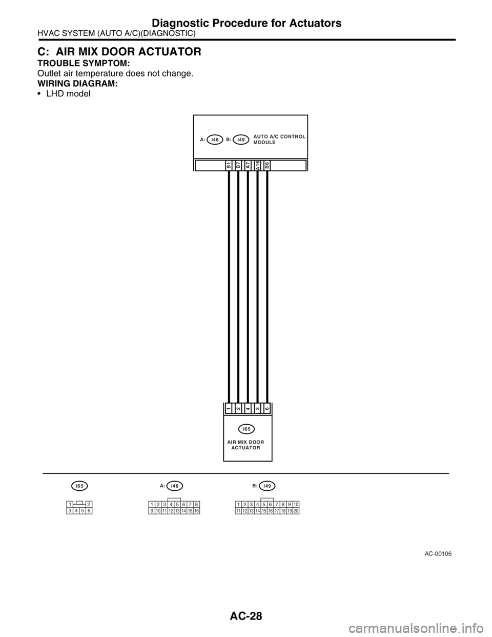
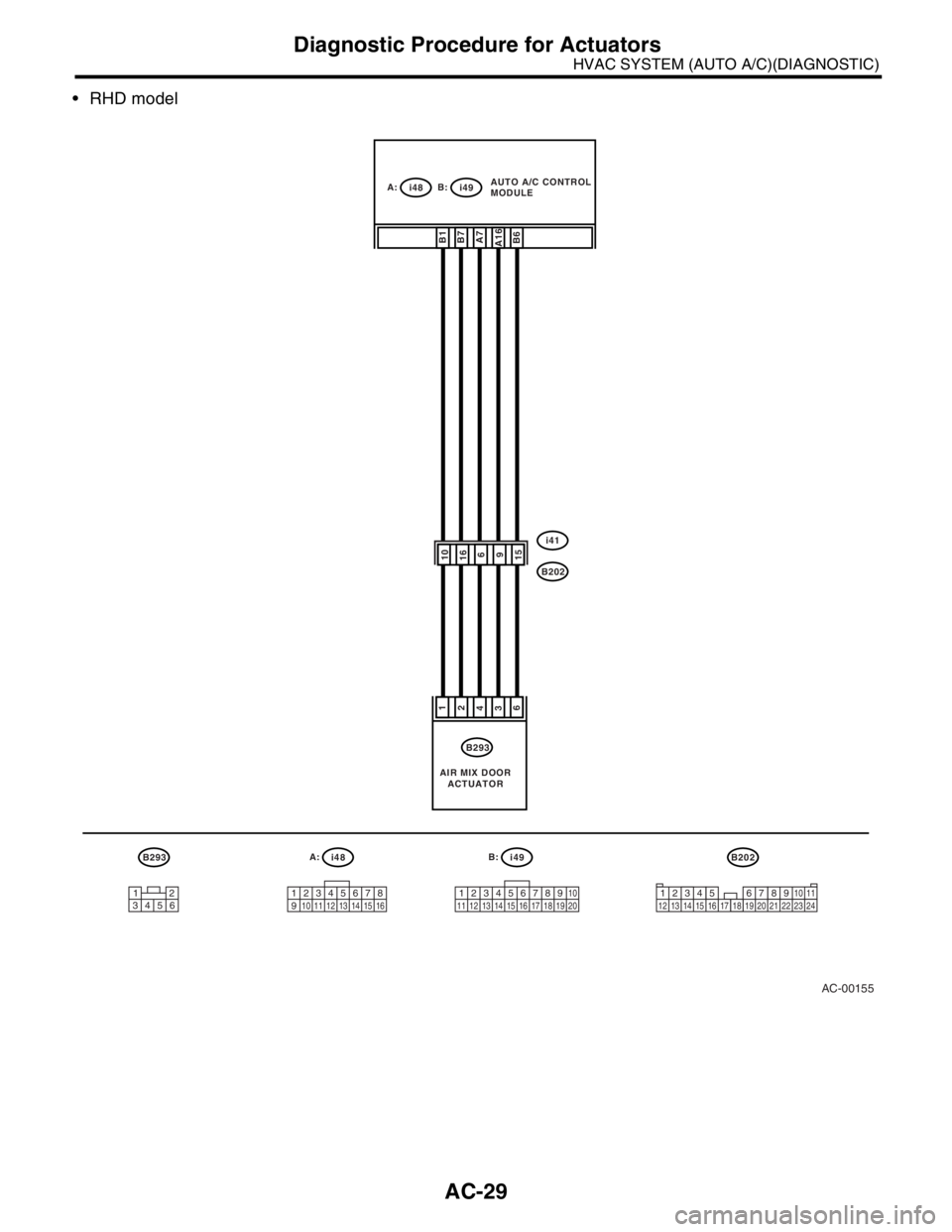
C: AIR MIX DOOR ACTUATOR
TROUBLE SYMPTOM:
Outlet air temperature does not change.
WIRING DIAGRAM:
LHD model
AC-00106
i65A:
i48B:
i49
12345678
910 11 12 13 14 15 1612345678910
11 12 13 14 15 16 17 18 19 20
i65
43126
A7A16B1B7B6
12
3456
A:
i48B:
i49AUTO A/C CONTROL
MODULE
AIR MIX DOOR
ACTUATOR
Page 85 of 2870

AC-29
HVAC SYSTEM (AUTO A/C)(DIAGNOSTIC)
Diagnostic Procedure for Actuators
RHD model
B293A:
i48B:
i49
12345678
910 11 12 13 14 15 1612345678910
11 12 13 14 15 16 17 18 19 20
B293
43126
A7A16B1B7B6
12
3456
A:
i48B:
i49AUTO A/C CONTROL
MODULE
AIR MIX DOOR
ACTUATOR
AC-00155
69101615
i41
B202
B202
3
4 128910 11
12 13 14 15 16 17 18 19 20 21 22 23 24567
Page 86 of 2870

AC-30
HVAC SYSTEM (AUTO A/C)(DIAGNOSTIC)
Diagnostic Procedure for Actuators
Step Check Yes No
1 CHECK POWER SUPPLY FOR AIR MIX
DOOR ACTUATOR POSITION SWITCH.
1) Turn the ignition switch to OFF.
2) Disconnect the air mix door actuator con-
nector.
3) Turn the ignition switch and AUTO switch to
ON.
4) Measure the voltage between auto A/C
control module connector terminals.
Connector & terminal
(i48) No. 7 (+) — (i48) No. 16 (
−):Is the voltage approx. 5 V? Go to step 2.Replace the auto
A/C control mod-
ule.
2 CHECK POWER SUPPLY FOR AIR MIX
DOOR ACTUATOR.
Measure the voltage between auto A/C control
module connector and chassis ground after
turning the temperature control dial to maxi-
mum COOL position.
Connector & terminal
(i49) No. 6 (+) — Chassis ground (
−):Is the voltage 7 V (at normal
temperature)?Go to step 3.Replace the auto
A/C control mod-
ule.
3 CHECK POWER SUPPLY FOR AIR MIX
DOOR ACTUATOR.
Measure the voltage between auto A/C control
module connector and chassis ground after
turning the temperature control dial to maxi-
mum HOT position.
Connector & terminal
(i49) No. 7 (+) — Chassis ground (
−):Is the voltage 7 V (at normal
temperature)?Go to step 4.Replace the auto
A/C control mod-
ule.
4 CHECK HARNESS BETWEEN AUTO A/C
CONTROL MODULE AND AIR MIX DOOR
ACTUATOR.
1) Turn the A/C and ignition switch to OFF.
2) Disconnect the auto A/C control module
connector.
3) Measure the resistance between auto A/C
control module and air mix door actuator con-
nector.
Connector & terminal
LHD model:
(i65) No. 1 — (i49) No. 1:
(i65) No. 2 — (i49) No. 7:
(i65) No. 3 — (i48) No. 16:
(i65) No. 4 — (i48) No. 7:
(i65) No. 6 — (i49) No. 6:
RHD model:
(B293) No. 1 — (i49) No. 1:
(B293) No. 2 — (i49) No. 7:
(B293) No. 3 — (i48) No. 16:
(B293) No. 4 — (i48) No. 7:
(B293) No. 6 — (i48) No. 6:Is the resistance less than 1
Ω?Go to step 5.Repair the har-
ness between auto
A/C control mod-
ule and air mix
door actuator.
Page 87 of 2870

AC-31
HVAC SYSTEM (AUTO A/C)(DIAGNOSTIC)
Diagnostic Procedure for Actuators
5 CHECK AIR MIX DOOR ACTUATOR POSI-
TION SWITCH SIGNAL.
1) Connect the connector of auto A/C control
module and air mix door actuator.
2) Turn the ignition switch and AUTO switch to
ON.
3) Check the voltage between auto A/C con-
trol module connector terminals while chang-
ing the setting temperature between maximum
COOL and maximum HOT.
Connector & terminal
(i49) No. 1 (+) — (i48) No. 16 (
−):Does the voltage change
between 0.5 (Max. HOT) — 4.5
(Max. COOL) V?Go to step 6.Replace the air
mix door actuator.
6 CHECK POOR CONTACT.
Check poor contact in auto A/C control module
and connector.Is there poor contact in con-
nector?Repair the con-
nector.Replace the auto
A/C control mod-
ule. Step Check Yes No
Page 88 of 2870

AC-32
HVAC SYSTEM (AUTO A/C)(DIAGNOSTIC)
Diagnostic Procedure for Sensors
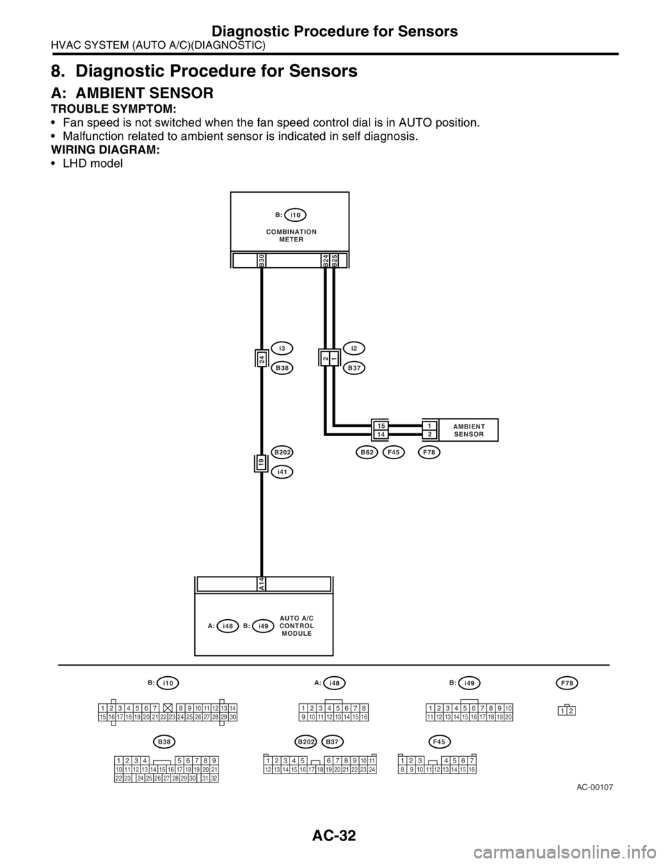
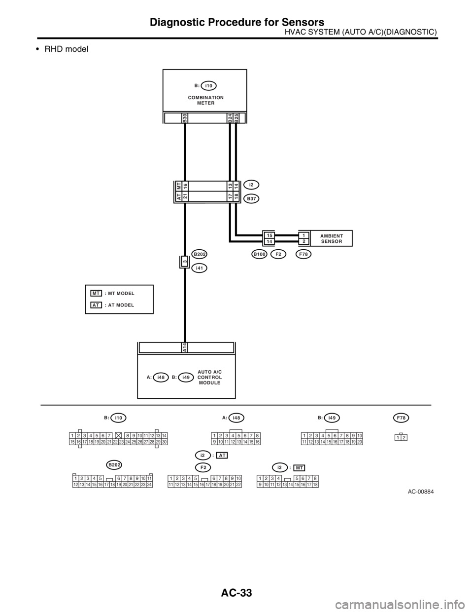
8. Diagnostic Procedure for Sensors
A: AMBIENT SENSOR
TROUBLE SYMPTOM:
Fan speed is not switched when the fan speed control dial is in AUTO position.
Malfunction related to ambient sensor is indicated in self diagnosis.
WIRING DIAGRAM:
LHD model
AC-00107
A:
i48B:
i49B:
i10
12345678
910 11 12 13 14 15 1612345678910
11 12 13 14 15 16 17 18 19 20
3
4 128910 11
12 13 14 15 16 17 18 19 20 21 22 23 24567
i41
B202
B202B38
i3
B38
B:
i10
COMBINATION
METER
A:
i48B:
i49
19
A14
24
B30
123456789101112131415161718192021222324252627282930
219
32
1234 5610 11 12 13 14 15716
23 3019 20
22 26 27 28 29817
24 3118
25
AUTO A/C
CONTROL
MODULE
i2
B37
141521
B24
B25
12
B62F45F78AMBIENT
SENSOR
B37
3
4 12
8910 11 12 13 14 15 16567
F45
12
F78
Page 89 of 2870

AC-33
HVAC SYSTEM (AUTO A/C)(DIAGNOSTIC)
Diagnostic Procedure for Sensors
RHD model
AC-00884
A:
i48B:
i49B:
i10
12345678
910 11 12 13 14 15 1612345678910
11 12 13 14 15 16 17 18 19 20
3
4 128910 11
12 13 14 15 16 17 18 19 20 21 22 23 24567
i41
B202
B202
B:
i10
COMBINATION
METER
A:
i48B:
i49
3 A14
B30
123456789101112131415161718192021222324252627282930
AUTO A/C
CONTROL
MODULE
i2
B37
141521
B24
B25
1817
B100F2F78AMBIENT
SENSOR
F2
12
F78
21
1413 16
: MT MODEL
: AT MODEL
3
4 128910
11
12 13 14 15 16 17 18 19 20 21 225673
4 12 8
910 11
12 13 14 15 16 17 185
67
i2 :
i2 :
MT AT
AT
MT AT MT
Page 90 of 2870

AC-34
HVAC SYSTEM (AUTO A/C)(DIAGNOSTIC)
Diagnostic Procedure for Sensors
Step Check Yes No
1 CHECK HARNESS CONNECTOR BETWEEN
AUTO A/C CONTROL MODULE AND COM-
BINATION METER.
1) Turn the ignition switch to OFF.
2) Disconnect the connector from auto A/C
control module and combination meter.
3) Measure the resistance in harness
between auto A/C control module and combi-
nation meter.
Connector & terminal
(i10) No. 30 — (i48) No. 14:Is the resistance less than 1
Ω?Go to step 2.Repair the har-
ness between auto
A/C control mod-
ule and combina-
tion meter.
2 CHECK AMBIENT SENSOR CIRCUIT.
Check the ambient sensor circuit.
CATOR, INSPECTION, Combination Meter
System.>Is the ambient sensor circuit
normal?Go to step 3.Repair the ambi-
ent sensor circuit.
3 CHECK POOR CONTACT.
Check poor contact in auto A/C control module
connector.Is there poor contact in con-
nector?Repair the con-
nector.Replace the A/C
control module.