SUBARU FORESTER 2004 Service Service Manual
FORESTER 2004
SUBARU
SUBARU
https://www.carmanualsonline.info/img/17/57426/w960_57426-0.png
SUBARU FORESTER 2004 Service Service Manual
Trending: check oil, gearbox, fuel, wheelbase, wiring diagram, navigation, fuel consumption
Page 41 of 2870
AC-39
HVAC SYSTEM (HEATER, VENTILATOR AND A/C)
Heater Cooling Unit
14.Heater Cooling Unit
A: REMOVAL
1) Disconnect the ground cable from battery.
2) Using the refrigerant recovery system, dis-
charge refrigerant.
Refrigerant Recovery Procedure.>
3) Drain the engine coolant from radiator.
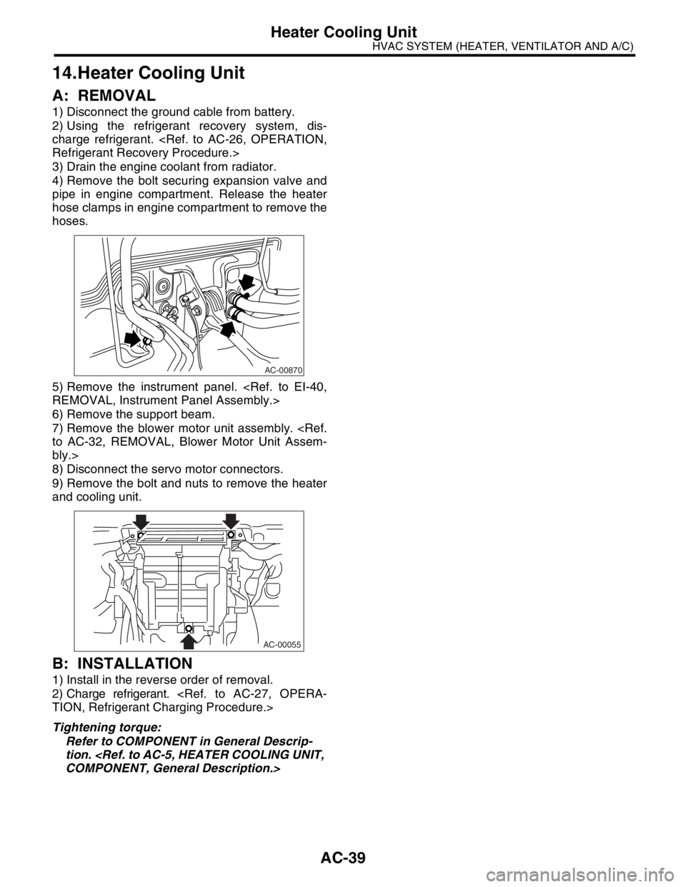
4) Remove the bolt securing expansion valve and
pipe in engine compartment. Release the heater
hose clamps in engine compartment to remove the
hoses.
5) Remove the instrument panel.
REMOVAL, Instrument Panel Assembly.>
6) Remove the support beam.
7) Remove the blower motor unit assembly.
to AC-32, REMOVAL, Blower Motor Unit Assem-
bly.>
8) Disconnect the servo motor connectors.
9) Remove the bolt and nuts to remove the heater
and cooling unit.
B: INSTALLATION
1) Install in the reverse order of removal.
2) Charge refrigerant.
TION, Refrigerant Charging Procedure.>
Tightening torque:
Refer to COMPONENT in General Descrip-
tion.
COMPONENT, General Description.>
AC-00870
AC-00055
Page 42 of 2870
AC-40
HVAC SYSTEM (HEATER, VENTILATOR AND A/C)
Evaporator
15.Evaporator
A: REMOVAL
1) Perform the refrigerant recovery operation, and
then disconnect the toe board area A/C pipe.
to AC-26, OPERATION, Refrigerant Recovery Pro-
cedure.>
2) Remove the glove box.
3) Remove blower motor unit assembly.
AC-32, REMOVAL, Blower Motor Unit Assembly.>
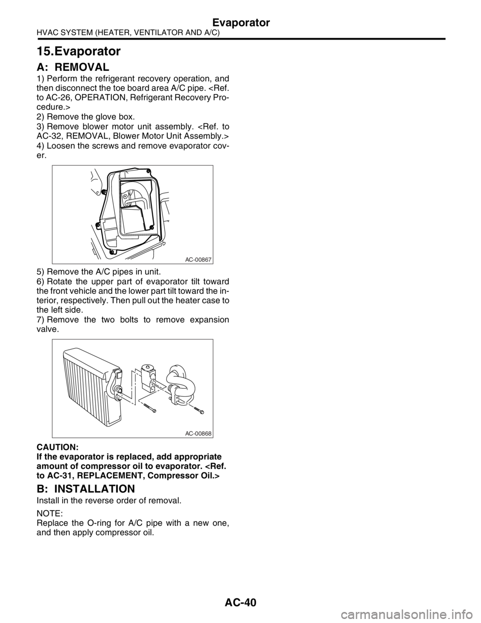
4) Loosen the screws and remove evaporator cov-
er.
5) Remove the A/C pipes in unit.
6) Rotate the upper part of evaporator tilt toward
the front vehicle and the lower part tilt toward the in-
terior, respectively. Then pull out the heater case to
the left side.
7) Remove the two bolts to remove expansion
valve.
CAUTION:
If the evaporator is replaced, add appropriate
amount of compressor oil to evaporator.
to AC-31, REPLACEMENT, Compressor Oil.>
B: INSTALLATION
Install in the reverse order of removal.
NOTE:
Replace the O-ring for A/C pipe with a new one,
and then apply compressor oil.
AC-00867
AC-00868
Page 43 of 2870
AC-41
HVAC SYSTEM (HEATER, VENTILATOR AND A/C)
Hose and Tube
16.Hose and Tube
A: REMOVAL
CAUTION:
When disconnecting/connecting hoses, do not
apply excessive force to them. Confirm that no
torsion and excessive tension exists after install-
ing.
Seal the disconnected hose with a plug or vi-
nyl tape to prevent foreign matters from enter-
ing.
1) Disconnect the ground cable from battery.
2) Using the refrigerant recovery system, dis-
charge refrigerant.
Refrigerant Recovery Procedure.>
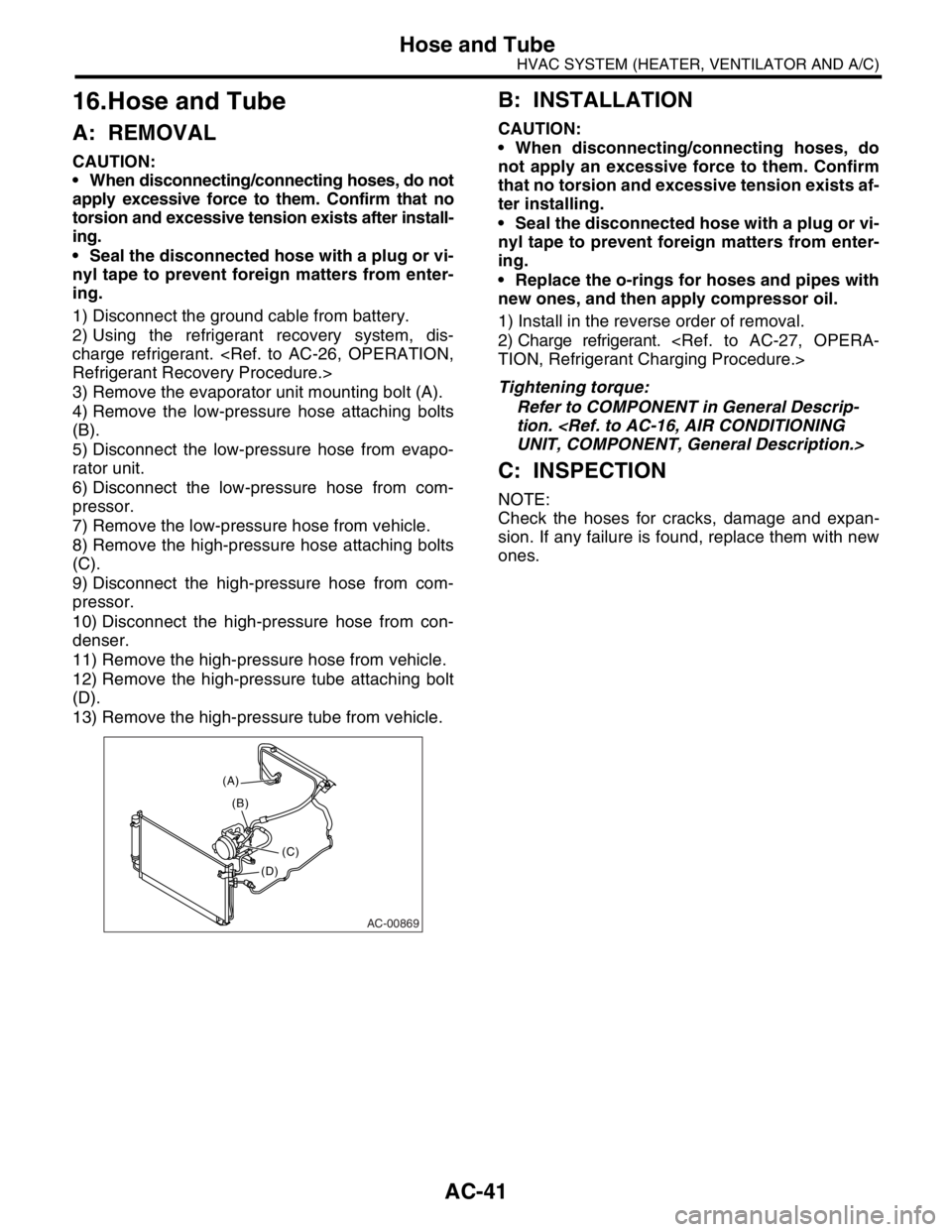
3) Remove the evaporator unit mounting bolt (A).
4) Remove the low-pressure hose attaching bolts
(B).
5) Disconnect the low-pressure hose from evapo-
rator unit.
6) Disconnect the low-pressure hose from com-
pressor.
7) Remove the low-pressure hose from vehicle.
8) Remove the high-pressure hose attaching bolts
(C).
9) Disconnect the high-pressure hose from com-
pressor.
10) Disconnect the high-pressure hose from con-
denser.
11) Remove the high-pressure hose from vehicle.
12) Remove the high-pressure tube attaching bolt
(D).
13) Remove the high-pressure tube from vehicle.
B: INSTALLATION
CAUTION:
When disconnecting/connecting hoses, do
not apply an excessive force to them. Confirm
that no torsion and excessive tension exists af-
ter installing.
Seal the disconnected hose with a plug or vi-
nyl tape to prevent foreign matters from enter-
ing.
Replace the o-rings for hoses and pipes with
new ones, and then apply compressor oil.
1) Install in the reverse order of removal.
2) Charge refrigerant.
TION, Refrigerant Charging Procedure.>
Tightening torque:
Refer to COMPONENT in General Descrip-
tion.
UNIT, COMPONENT, General Description.>
C: INSPECTION
NOTE:
Check the hoses for cracks, damage and expan-
sion. If any failure is found, replace them with new
ones.
AC-00869
(A)
(C) (B)
(D)
Page 44 of 2870
AC-42
HVAC SYSTEM (HEATER, VENTILATOR AND A/C)
Relay and Fuse
17.Relay and Fuse
A: LOCATIONB: INSPECTION
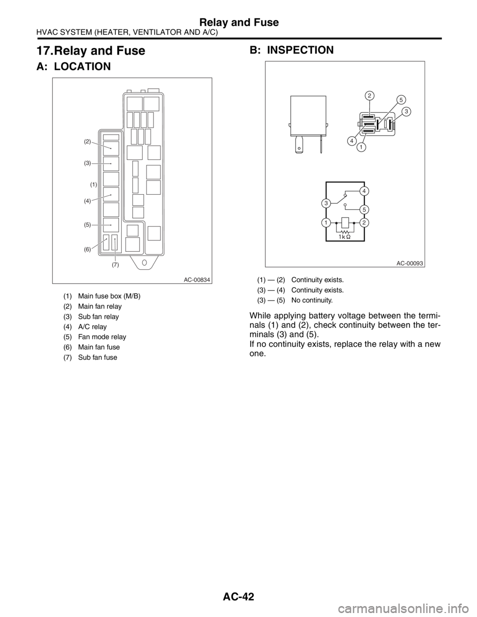
While applying battery voltage between the termi-
nals (1) and (2), check continuity between the ter-
minals (3) and (5).
If no continuity exists, replace the relay with a new
one.
(1) Main fuse box (M/B)
(2) Main fan relay
(3) Sub fan relay
(4) A/C relay
(5) Fan mode relay
(6) Main fan fuse
(7) Sub fan fuse
AC-00834
(7) (6) (5) (4)(1) (3) (2)
(1) — (2) Continuity exists.
(3) — (4) Continuity exists.
(3) — (5) No continuity.
AC-00093
4
4
5
2
25
3
3
1
1
Page 45 of 2870
AC-43
HVAC SYSTEM (HEATER, VENTILATOR AND A/C)
Pressure Switch (Triple Pressure Switch)
18.Pressure Switch (Triple Pres-
sure Switch)
A: INSPECTION
1) Connect the manifold gauge to the service valve
on the high-pressure side.
2) Remove the pressure switch harness connector.
Using a circuit tester, inspect the ON-OFF opera-
tion of the pressure switch.
AC-00248
31
4
2
Terminal
No.OperationStandard
kPa (kg/cm2, psi)
High and low pressure switch 1 and 2Tu r n s O F F.Pressure increases up to 2,940±200 (30.0±2, 427±28).
Pressure decreases down to 177±25 (1.8±0.3, 26±4).
Tu r n s O N .Pressure increases up to 206±30 (2.1±0.3, 30±4).
Pressure decreases down to 2,350±200 (24±2, 341±28).
Middle pressure switch 3 and 4Turns OFF. Pressure decreases down to 1,370±120 (14±1, 199±14).
Turns ON. Pressure increases up to 1,770±100 (18±1, 256±14).
Page 46 of 2870
AC-44
HVAC SYSTEM (HEATER, VENTILATOR AND A/C)
Ambient Sensor (Auto A/C Model)
19.Ambient Sensor (Auto A/C
Model)
A: REMOVAL
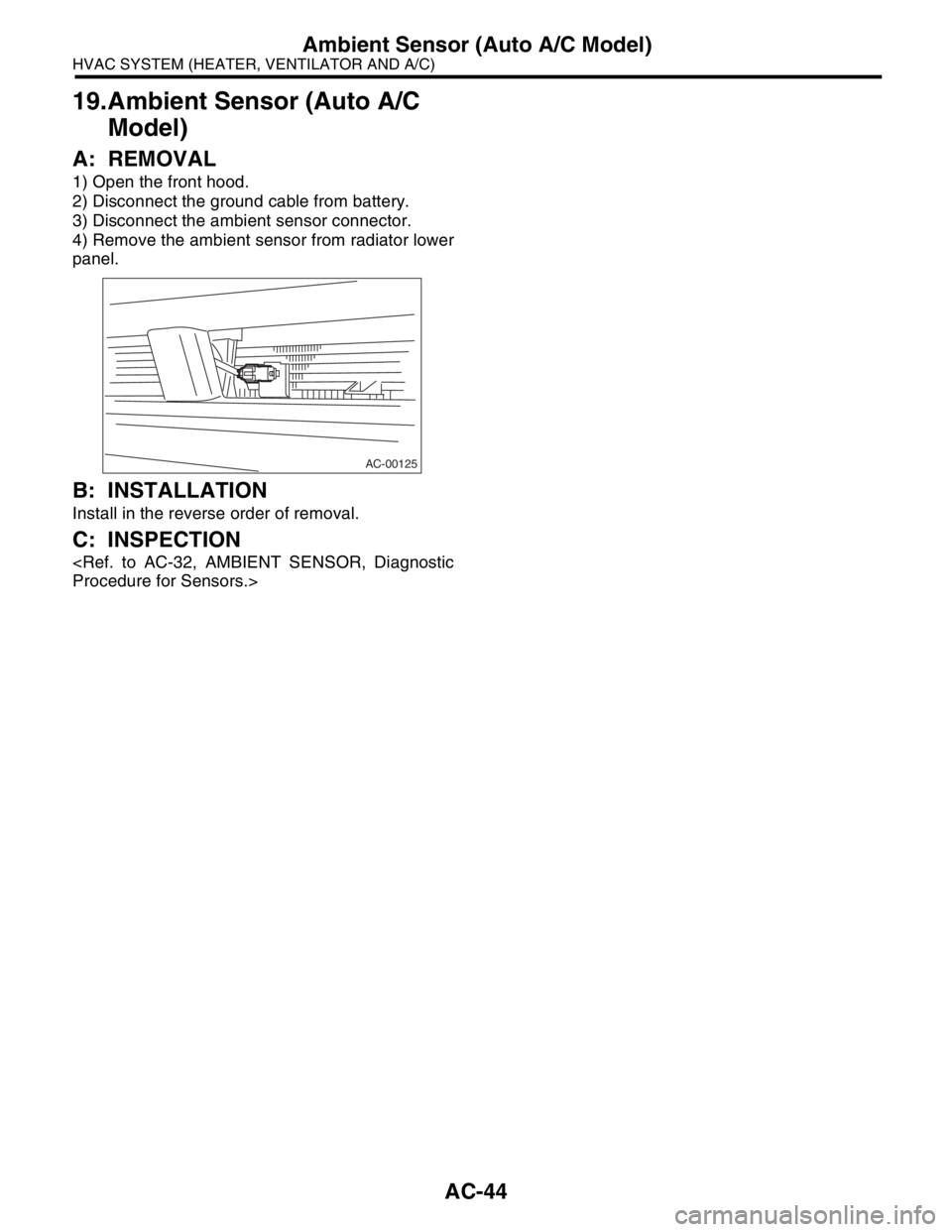
1) Open the front hood.
2) Disconnect the ground cable from battery.
3) Disconnect the ambient sensor connector.
4) Remove the ambient sensor from radiator lower
panel.
B: INSTALLATION
Install in the reverse order of removal.
C: INSPECTION
Procedure for Sensors.>
AC-00125
Page 47 of 2870
AC-45
HVAC SYSTEM (HEATER, VENTILATOR AND A/C)
Sunload Sensor (Auto A/C Model)
20.Sunload Sensor (Auto A/C
Model)
A: REMOVAL
1) Disconnect the ground cable from battery.
2) Disconnect the sunload sensor connector.
CAUTION:
Be careful not to damage the sensors and inte-
rior trims when removing them.
B: INSTALLATION
Install in the reverse order of removal.
C: INSPECTION
Procedure for Sensors.>
AC-00126
Page 48 of 2870
AC-46
HVAC SYSTEM (HEATER, VENTILATOR AND A/C)
Air Vent Grille
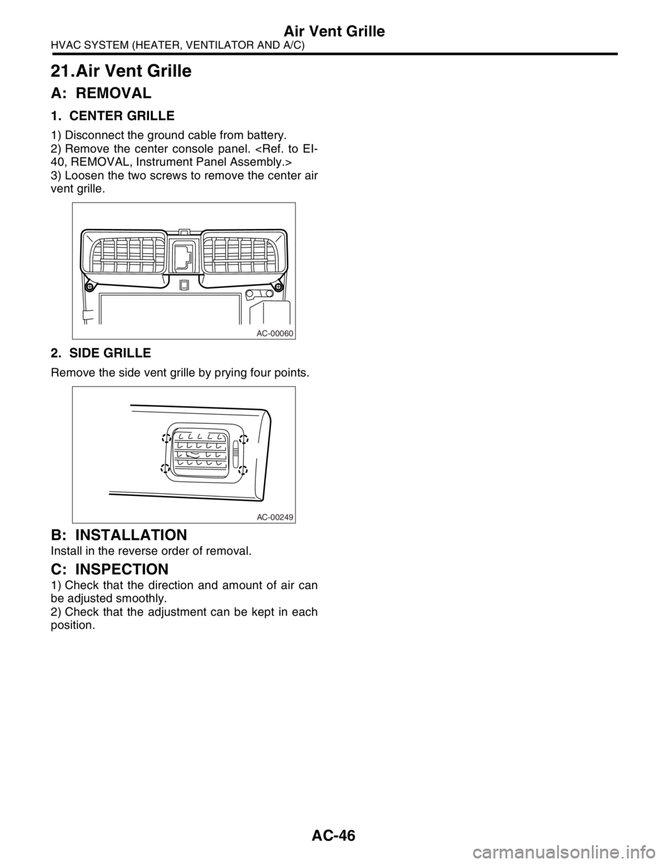
21.Air Vent Grille
A: REMOVAL
1. CENTER GRILLE
1) Disconnect the ground cable from battery.
2) Remove the center console panel.
40, REMOVAL, Instrument Panel Assembly.>
3) Loosen the two screws to remove the center air
vent grille.
2. SIDE GRILLE
Remove the side vent grille by prying four points.
B: INSTALLATION
Install in the reverse order of removal.
C: INSPECTION
1) Check that the direction and amount of air can
be adjusted smoothly.
2) Check that the adjustment can be kept in each
position.
AC-00060
AC-00249
Page 49 of 2870
AC-47
HVAC SYSTEM (HEATER, VENTILATOR AND A/C)
Heater Duct
22.Heater Duct
A: REMOVAL
1) Remove the front seat.
AL, Front Seat.>
2) Remove the front side sill cover.
3) Pull off the floor mat, remove the cover, and then
remove the heater duct.
B: INSTALLATION
Install in the reverse order of removal.
Page 50 of 2870
AC-48
HVAC SYSTEM (HEATER, VENTILATOR AND A/C)
Heater Vent Duct
23.Heater Vent Duct
A: REMOVAL
1) Remove the instrument panel.
2) Remove the screws.
3) Remove the heater vent duct.
B: INSTALLATION
Install in the reverse order of removal.
AC-00224
Trending: brakes torque, wheel alignment, power steering fluid, Steering, overheating, child lock, oil pressure
