SUBARU FORESTER 2004 Service Workshop Manual
Manufacturer: SUBARU, Model Year: 2004, Model line: FORESTER, Model: SUBARU FORESTER 2004Pages: 2870, PDF Size: 38.67 MB
Page 51 of 2870

AC-49
HVAC SYSTEM (HEATER, VENTILATOR AND A/C)
Heater Cock Solenoid Valve
24.Heater Cock Solenoid Valve
A: REMOVAL
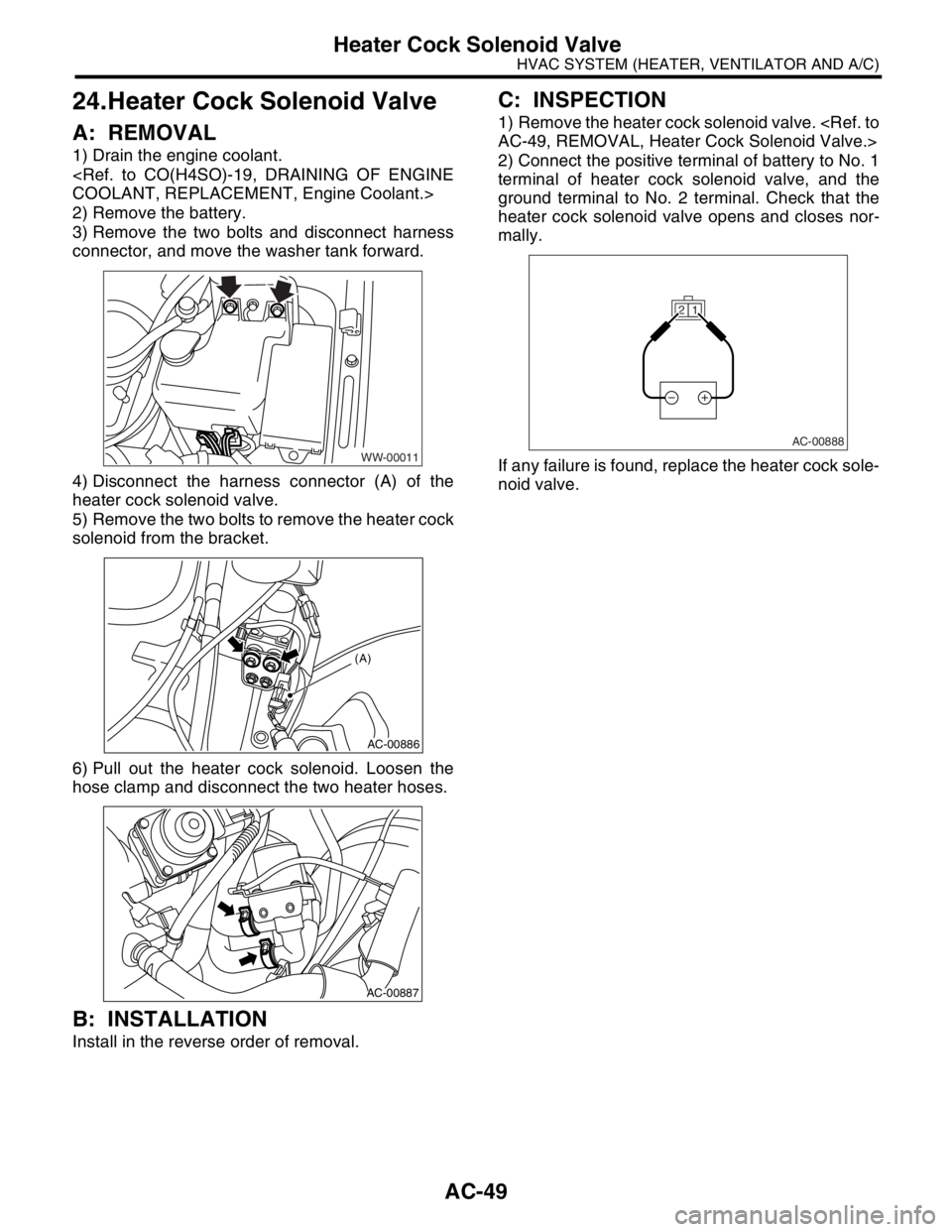
1) Drain the engine coolant.
2) Remove the battery.
3) Remove the two bolts and disconnect harness
connector, and move the washer tank forward.
4) Disconnect the harness connector (A) of the
heater cock solenoid valve.
5) Remove the two bolts to remove the heater cock
solenoid from the bracket.
6) Pull out the heater cock solenoid. Loosen the
hose clamp and disconnect the two heater hoses.
B: INSTALLATION
Install in the reverse order of removal.
C: INSPECTION
1) Remove the heater cock solenoid valve.
2) Connect the positive terminal of battery to No. 1
terminal of heater cock solenoid valve, and the
ground terminal to No. 2 terminal. Check that the
heater cock solenoid valve opens and closes nor-
mally.
If any failure is found, replace the heater cock sole-
noid valve.
WW-00011
AC-00886
(A)
AC-00887
1 2
AC-00888
Page 52 of 2870

AC-50
HVAC SYSTEM (HEATER, VENTILATOR AND A/C)
General Diagnostics
25.General Diagnostics
A: INSPECTION
Symptom Repair order
Blower motorDoes not run.Fuse
Blower motor relay
Wiring harness
Blower motor
Blower motor resistor (Manual A/C model)
Blower switch
Noise Blower motor
CompressorDoes not run.Refrigerant
Fuse
A/C relay
Wiring harness
Magnet clutch
Compressor
Pressure switch
A/C switch
Blower switch
NoiseV- B e l t
Magnet clutch
Compressor
Condenser fanDoes not run.Fuse
Sub fan relay
Wiring harness
Noise Condenser fan motor
Cold air not emitted.Refrigerant
V- B e l t
Magnet clutch
Compressor
Pressure switch
Blower fan relay, Blower motor
A/C switch
Blower switch
Wiring harness
Heater duct
Heater vent duct
Control unit
Expansion valve
Evaporator
Air mix actuator (Auto A/C), Temperature control cable (Manual
A/C)
Warm air not emitted.Engine coolant
Aspirator hose
Blower switch
Air mix actuator (Auto A/C), Temperature control cable (Manual
A/C)
Heater core
Heater cock solenoid valve (Non-turbo model for EC/EK)
Page 53 of 2870

AC-51
HVAC SYSTEM (HEATER, VENTILATOR AND A/C)
General Diagnostics
Temperature of air from vents does not change.Wiring harness
Air mix actuator (Auto A/C), Temperature control cable (Manual
A/C)
Temperature adjustment switch
Unable to switch blow vents.Wiring harness
Mode actuator (Auto A/C), Mode control cable (Manual A/C)
Mode switch
Unable to switch suction vents.Wiring harness
FRESH/RECIRC actuator
Air inlet select switch Symptom Repair order
Page 54 of 2870

AC-52
HVAC SYSTEM (HEATER, VENTILATOR AND A/C)
General Diagnostics
Page 55 of 2870

FUJI HEAVY INDUSTRIES LTD. G8080GE7
2004 FORESTER SERVICE MANUAL QUICK REFERENCE INDEX
BODY SECTION
This service manual has been prepared
to provide SUBARU service personnel
with the necessary information and data
for the correct maintenance and repair
of SUBARU vehicles.
This manual includes the procedures
for maintenance, disassembling, reas-
sembling, inspection and adjustment of
components and diagnostics for guid-
ance of experienced mechanics.
Please peruse and utilize this manual
fully to ensure complete repair work for
satisfying our customers by keeping
their vehicle in optimum condition.
When replacement of parts during
repair work is needed, be sure to use
SUBARU genuine parts.
All information, illustration and specifi-
cations contained in this manual are
based on the latest product information
available at the time of publication
approval.HVAC SYSTEM
(HEATER, VENTILATOR AND A/C)AC
HVAC SYSTEM (AUTO A/C)
(DIAGNOSTIC)AC
AIRBAG SYSTEM AB
AIRBAG SYSTEM (DIAGNOSTIC) AB
SEAT BELT SYSTEM SB
LIGHTING SYSTEM LI
WIPER AND WASHER SYSTEM WW
ENTERTAINMENT ET
COMMUNICATION SYSTEM COM
GLASS/WINDOW/MIRROR GW
BODY STRUCTURE BS
INSTRUMENTATION/DRIVER INFO IDI
SEAT SE
SECURITY AND LOCK SL
SUNROOF/T-TOP/CONVERTIBLE TOP
(SUNROOF)SR
EXTERIOR/INTERIOR TRIM EI
EXTERIOR BODY PANEL EB
Page 56 of 2870

2004 FORESTER SERVICE MANUAL QUICK REFERENCE INDEX
BODY SECTION
G8080GE7
CRUISE CONTROL SYSTEM CC
CRUISE CONTROL SYSTEM
(DIAGNOSTIC)CC(H4SO)
CRUISE CONTROL SYSTEM
(DIAGNOSTIC)CC(H4DOTC)
CRUISE CONTROL SYSTEM
(DIAGNOSTIC)CC(H4DOTC 2.5)
IMMOBILIZER (DIAGNOSTIC) IM
Page 57 of 2870

HVAC SYSTEM (AUTO A/C)(DIAGNOSTIC)
AC
Page
1. Basic Diagnostics Procedure ......................................................................2
2. General Description ....................................................................................3
3. Electrical Component Location ...................................................................5
4. Auto A/C Control Module I/O Signal............................................................7
5. Diagnostic Chart for Self-Diagnosis ............................................................9
6. Diagnostics for A/C System Malfunction ...................................................12
7. Diagnostic Procedure for Actuators ..........................................................21
8. Diagnostic Procedure for Sensors ............................................................32
9. General Diagnostic Table..........................................................................41
Page 58 of 2870

AC-2
HVAC SYSTEM (AUTO A/C)(DIAGNOSTIC)
Basic Diagnostics Procedure
1. Basic Diagnostics Procedure
A: PROCEDURE
Step Check Yes No
1 START INSPECTIONS.
1) Perform the pre-inspection.
2) Perform the self-diagnosis.
nosis.>Does the self-diagnosis oper-
ate?Go to step 2.
NOSIS SYS-
TEMS DO NOT
OPERATE, Diag-
nostics for A/C
System Malfunc-
tion.>
2 IDENTIFY MALFUNCTION PART.
Identify the malfunction part with self-diagno-
sis.Can the malfunction part be
identified?Repair the mal-
function part in
accordance with
each diagnostic
chart.Go to step 3.
3 CHECK COMPARTMENT TEMPERATURE.
1) Turn ON the A/C switch.
2) Turn the temperature control dial at maxi-
mum cool position.
3) Check the compartment temperature
change.Does the compartment tem-
perature change?Go to step 4.
TEMPERATURE
DOES NOT
CHANGE, OR A/C
SYSTEM DOES
NOT RESPOND
PROMPTLY.,
Diagnostics for A/
C System Mal-
function.>
4 CHECK A/C SYSTEM RESPONSE.
Change the temperature setting, and check the
response of A/C system.Does the A/C system respond
quickly?A/C system is nor-
mal.
TEMPERATURE
DOES NOT
CHANGE, OR A/C
SYSTEM DOES
NOT RESPOND
PROMPTLY.,
Diagnostics for A/
C System Mal-
function.>
Page 59 of 2870

AC-3
HVAC SYSTEM (AUTO A/C)(DIAGNOSTIC)
General Description
2. General Description
A: CAUTION
1) Never connect the battery in reverse polarity.
Auto A/C control module may be destroyed instant-
ly.
2) Do not disconnect the battery terminals while the
engine is running.
A large counter electromotive force will be generat-
ed in the generator, and this voltage may damage
electronic parts such as auto A/C control module,
etc.
3) Before disconnecting the connectors of each
sensor and the auto A/C control module, be sure to
turn off the ignition switch.
Auto A/C control module may be damaged.
4) Every A/C-related part is a precision part. Do not
drop them.
5) Airbag system wiring harness is routed near the
A/C control panel (auto A/C control module) and
junction box.
CAUTION:
For airbag system, yellow-colored wiring har-
ness and connectors are all used. Do not use
the electrical test equipment on these circuits.
Be careful not to damage the airbag system
wiring harness when servicing the A/C control
panel (auto A/C control module) and junction
box.
B: INSPECTION
Before performing the diagnosis, check the follow-
ing items which might affect A/C system problems.
1. BATTERY
1) Measure battery voltage and specific gravity of
electrolyte.
Standard voltage: 12 V
Specific gravity: More than 1.260
2) Check the condition of the fuses for A/C system
power supply and other fuses.
3) Check the condition of harness and harness
connector connections.
2. ASPIRATOR HOSE
1) Turn the ignition switch to ON, and press the A/
C switch.
2) Turn the temperature control dial at maximum
hot position.
3) Press the defroster switch.
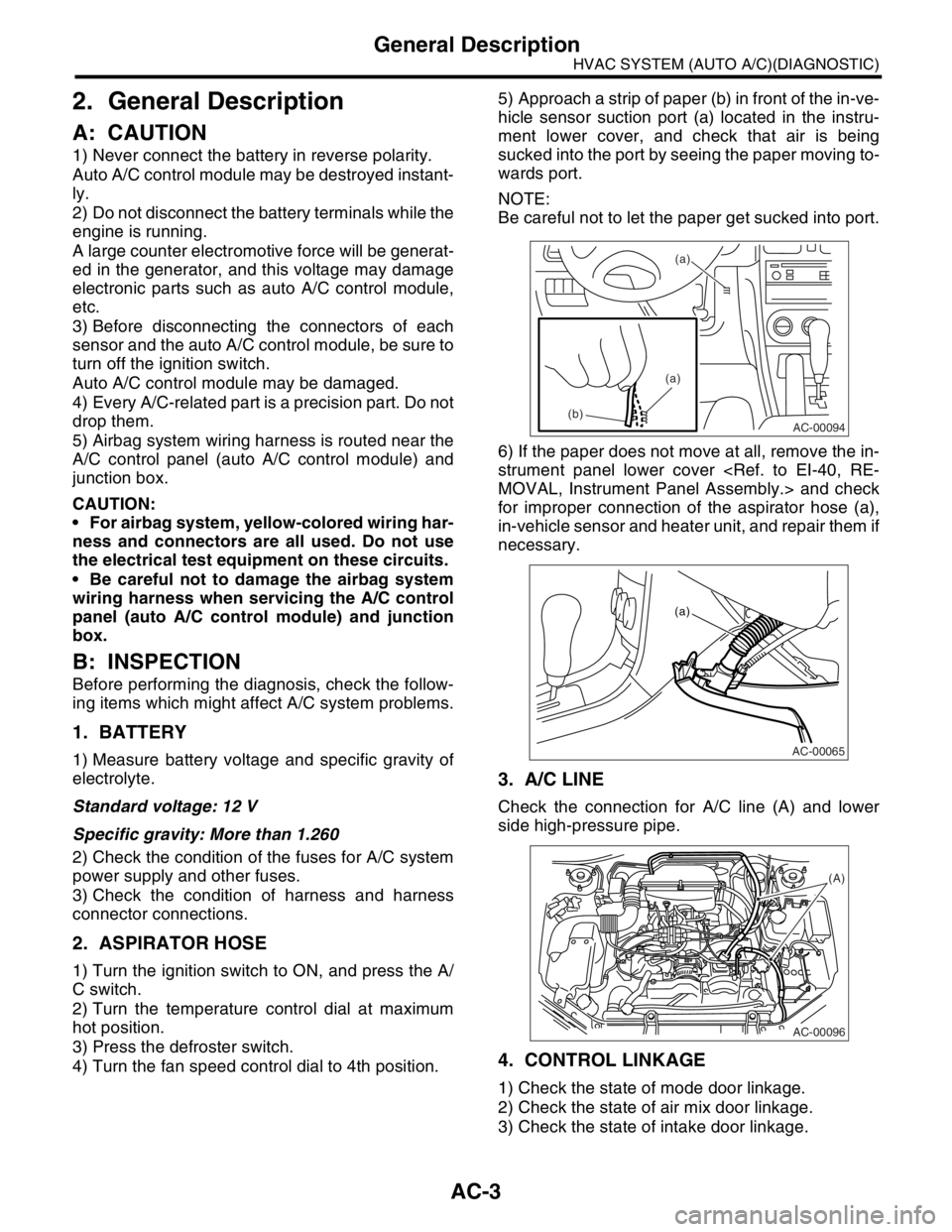
4) Turn the fan speed control dial to 4th position.5) Approach a strip of paper (b) in front of the in-ve-
hicle sensor suction port (a) located in the instru-
ment lower cover, and check that air is being
sucked into the port by seeing the paper moving to-
wards port.
NOTE:
Be careful not to let the paper get sucked into port.
6) If the paper does not move at all, remove the in-
strument panel lower cover
for improper connection of the aspirator hose (a),
in-vehicle sensor and heater unit, and repair them if
necessary.
3. A/C LINE
Check the connection for A/C line (A) and lower
side high-pressure pipe.
4. CONTROL LINKAGE
1) Check the state of mode door linkage.
2) Check the state of air mix door linkage.
3) Check the state of intake door linkage.
AC-00094
(a)
(a)
(b)
AC-00065
(a)
AC-00096
(A)
Page 60 of 2870

AC-4
HVAC SYSTEM (AUTO A/C)(DIAGNOSTIC)
General Description
5. CONTROL SWITCHES
Start and warm-up the engine completely.
1) Inspection using switches
2) Compressor operation inspection
3) Inspection of illumination control
No. Point to check Switch operation Judgment standard
1 Fan speed control dial Turn the fan speed control dial clockwise.Fan speed changes 1st → 2nd → 3rd → 4th
as dial turn.
2AUTO switch1) Press the AUTO switch.
2) Turn the temperature control dial to the left
fully, and set maximum cool position. Outlet air temperature: COOL
Fan speed: 4th
Outlet opening: VENT
Inlet opening: RECIRC
Compressor: AUTO
3) Turn the temperature control dial to the right
slowly, and change the setting from maximum
cool position to maximum hot position gradually. Outlet air temperature: COOL → HOT
Fan speed: AUTO
Outlet opening: AUTO
Inlet opening: AUTO
Compressor: AUTO
4) Turn the temperature control dial to the right
fully, and set maximum hot position. Outlet air temperature: HOT
Fan speed: 4th
Outlet opening: HEAT
Inlet opening: FRESH
Compressor: AUTO
3 Defroster switch Press the defroster switch. Outlet air temperature: AUTO
Fan speed: AUTO
Outlet opening: DEF
Inlet opening: FRESH
Compressor: ON
4FRESH/RECIRC
switchPress the FRESH/RECIRC switch.Inlet opening switches RECIRC → FRESH or
FRESH → RECIRC each time pressing the
switch.
5 Mode control dial Press the mode control dial.Outlet opening switches VENT → BI-LEVEL
→ HEAT → DEF/HEAT each time dialing
clockwise.
No. Point to check Switch operation Judgment standard
1 Compressor1) A/C switch is turned to ON.
2) Turn the fan speed control clockwise.Compressor: ON
No. Point to check Switch operation Judgment standard
1 Illumination1) Turn the lighting switch to ON. Illumination comes on.
2) Press the OFF switch one second or more. Illumination dimming is cancelled.