SUBARU TRIBECA 2009 1.G Service Workshop Manual
Manufacturer: SUBARU, Model Year: 2009, Model line: TRIBECA, Model: SUBARU TRIBECA 2009 1.GPages: 2453, PDF Size: 46.32 MB
Page 1941 of 2453
ME(H6DO)-75
Cylinder Block
MECHANICAL
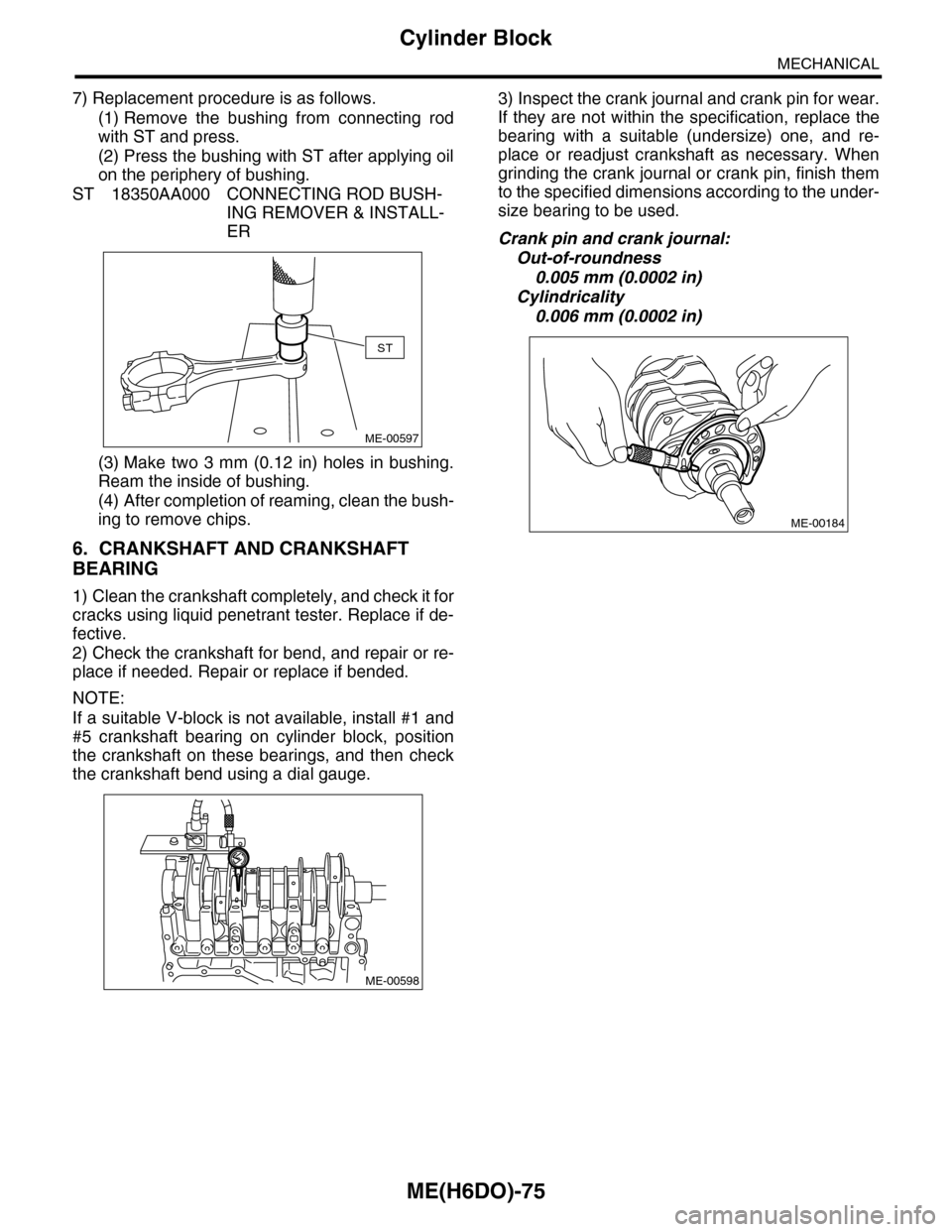
7) Replacement procedure is as follows.
(1) Remove the bushing from connecting rod
with ST and press.
(2) Press the bushing with ST after applying oil
on the periphery of bushing.
ST 18350AA000 CONNECTING ROD BUSH-
ING REMOVER & INSTALL-
ER
(3) Make two 3 mm (0.12 in) holes in bushing.
Ream the inside of bushing.
(4) After completion of reaming, clean the bush-
ing to remove chips.
6. CRANKSHAFT AND CRANKSHAFT
BEARING
1) Clean the crankshaft completely, and check it for
cracks using liquid penetrant tester. Replace if de-
fective.
2) Check the crankshaft for bend, and repair or re-
place if needed. Repair or replace if bended.
NOTE:
If a suitable V-block is not available, install #1 and
#5 crankshaft bearing on cylinder block, position
the crankshaft on these bearings, and then check
the crankshaft bend using a dial gauge.
3) Inspect the crank journal and crank pin for wear.
If they are not within the specification, replace the
bearing with a suitable (undersize) one, and re-
place or readjust crankshaft as necessary. When
grinding the crank journal or crank pin, finish them
to the specified dimensions according to the under-
size bearing to be used.
Crank pin and crank journal:
Out-of-roundness
0.005 mm (0.0002 in)
Cylindricality
0.006 mm (0.0002 in)
ST
ME-00597
ME-00598
ME-00184
Page 1942 of 2453
ME(H6DO)-76
Cylinder Block
MECHANICAL
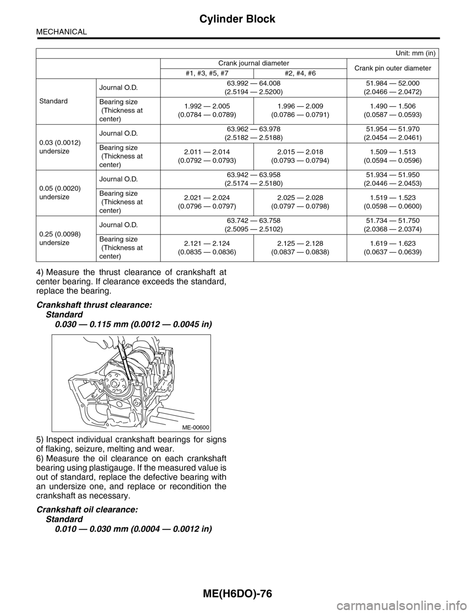
4) Measure the thrust clearance of crankshaft at
center bearing. If clearance exceeds the standard,
replace the bearing.
Crankshaft thrust clearance:
Standard
0.030 — 0.115 mm (0.0012 — 0.0045 in)
5) Inspect individual crankshaft bearings for signs
of flaking, seizure, melting and wear.
6) Measure the oil clearance on each crankshaft
bearing using plastigauge. If the measured value is
out of standard, replace the defective bearing with
an undersize one, and replace or recondition the
crankshaft as necessary.
Crankshaft oil clearance:
Standard
0.010 — 0.030 mm (0.0004 — 0.0012 in)
Unit: mm (in)
Crank journal diameterCrank pin outer diameter#1, #3, #5, #7 #2, #4, #6
Standard
Journal O.D.63.992 — 64.008
(2.5194 — 2.5200)
51.984 — 52.000
(2.0466 — 2.0472)
Bearing size
(Thickness at
center)
1.992 — 2.005
(0.0784 — 0.0789)
1.996 — 2.009
(0.0786 — 0.0791)
1.490 — 1.506
(0.0587 — 0.0593)
0.03 (0.0012)
undersize
Journal O.D.63.962 — 63.978
(2.5182 — 2.5188)
51.954 — 51.970
(2.0454 — 2.0461)
Bearing size
(Thickness at
center)
2.011 — 2.014
(0.0792 — 0.0793)
2.015 — 2.018
(0.0793 — 0.0794)
1.509 — 1.513
(0.0594 — 0.0596)
0.05 (0.0020)
undersize
Journal O.D.63.942 — 63.958
(2.5174 — 2.5180)
51.934 — 51.950
(2.0446 — 2.0453)
Bearing size
(Thickness at
center)
2.021 — 2.024
(0.0796 — 0.0797)
2.025 — 2.028
(0.0797 — 0.0798)
1.519 — 1.523
(0.0598 — 0.0600)
0.25 (0.0098)
undersize
Journal O.D.63.742 — 63.758
(2.5095 — 2.5102)
51.734 — 51.750
(2.0368 — 2.0374)
Bearing size
(Thickness at
center)
2.121 — 2.124
(0.0835 — 0.0836)
2.125 — 2.128
(0.0837 — 0.0838)
1.619 — 1.623
(0.0637 — 0.0639)
ME-00600
Page 1943 of 2453
ME(H6DO)-77
Oil Flow Control Solenoid Valve
MECHANICAL
22.Oil Flow Control Solenoid
Valve
A: REMOVAL
Oil flow control solenoid valve is a unit with cam-
shaft cap.
Refer to "Camshaft" for removal.
B: INSTALLATION
Install in the reverse order of removal.
Page 1944 of 2453
ME(H6DO)-78
Oil Switching Solenoid Valve
MECHANICAL
23.Oil Switching Solenoid Valve
A: REMOVAL
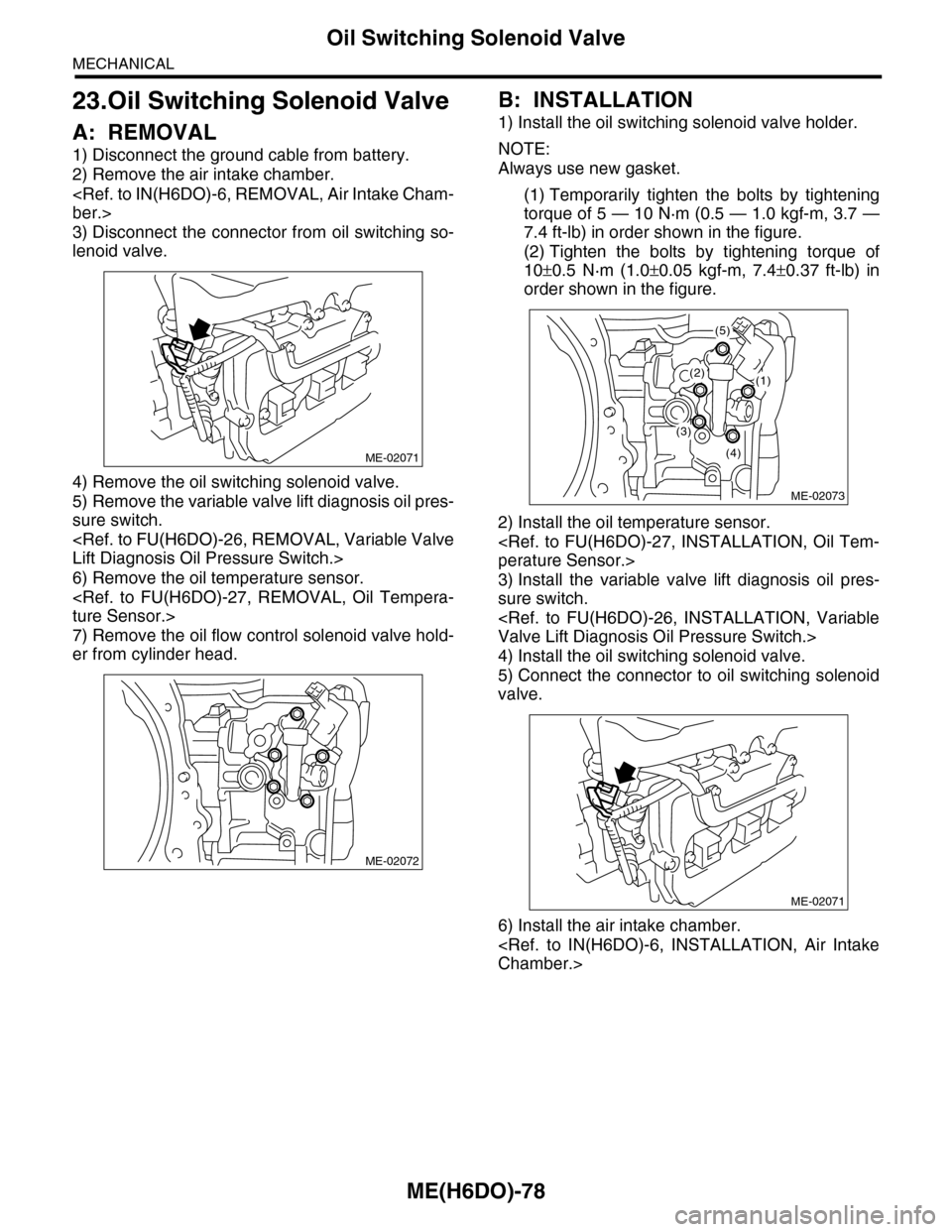
1) Disconnect the ground cable from battery.
2) Remove the air intake chamber.
3) Disconnect the connector from oil switching so-
lenoid valve.
4) Remove the oil switching solenoid valve.
5) Remove the variable valve lift diagnosis oil pres-
sure switch.
6) Remove the oil temperature sensor.
7) Remove the oil flow control solenoid valve hold-
er from cylinder head.
B: INSTALLATION
1) Install the oil switching solenoid valve holder.
NOTE:
Always use new gasket.
(1) Temporarily tighten the bolts by tightening
torque of 5 — 10 N·m (0.5 — 1.0 kgf-m, 3.7 —
7.4 ft-lb) in order shown in the figure.
(2) Tighten the bolts by tightening torque of
10±0.5 N·m (1.0±0.05 kgf-m, 7.4±0.37 ft-lb) in
order shown in the figure.
2) Install the oil temperature sensor.
3) Install the variable valve lift diagnosis oil pres-
sure switch.
4) Install the oil switching solenoid valve.
5) Connect the connector to oil switching solenoid
valve.
6) Install the air intake chamber.
ME-02071
ME-02072
ME-02073
(2)(1)
(5)
(4)
(3)
ME-02071
Page 1945 of 2453
ME(H6DO)-79
Intake and Exhaust Valve
MECHANICAL
24.Intake and Exhaust Valve
A: SPECIFICATION
Refer to “Cylinder Head” for removal and installa-
tion procedures of intake and exhaust valves
Page 1946 of 2453
ME(H6DO)-80
Piston
MECHANICAL
25.Piston
A: SPECIFICATION
Refer to “Cylinder Block” for removal and installa-
tion procedures of pistons.
Page 1947 of 2453
ME(H6DO)-81
Connecting Rod
MECHANICAL
26.Connecting Rod
A: SPECIFICATION
Refer to “Cylinder Block” for removal and installa-
tion procedures of connecting rod.
Page 1948 of 2453
ME(H6DO)-82
Crankshaft
MECHANICAL
27.Crankshaft
A: SPECIFICATION
Refer to “Cylinder Block” for removal and installa-
tion procedures of crankshaft.
Page 1949 of 2453
ME(H6DO)-83
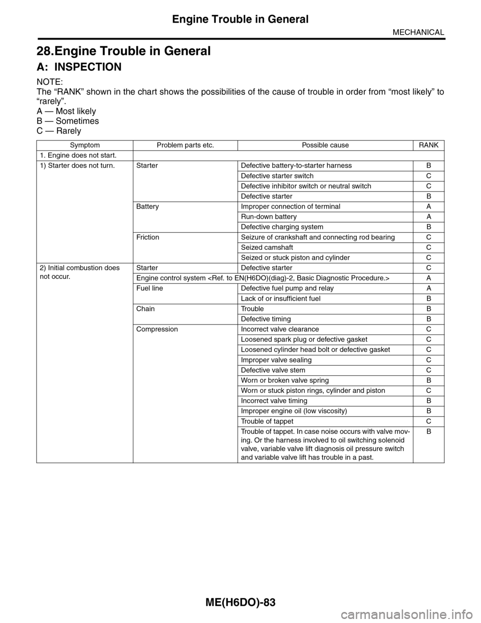
Engine Trouble in General
MECHANICAL
28.Engine Trouble in General
A: INSPECTION
NOTE:
The “RANK” shown in the chart shows the possibilities of the cause of trouble in order from “most likely” to
“rarely”.
A — Most likely
B — Sometimes
C — Rarely
Symptom Problem parts etc. Possible cause RANK
1. Engine does not start.
1) Starter does not turn. Starter Defective battery-to-starter harness B
Defective starter switch C
Defective inhibitor switch or neutral switch C
Defective starter B
Battery Improper connection of terminal A
Run-down battery A
Defective charging system B
Fr iction Seizure of crankshaft and connecting rod bear ing C
Seized camshaft C
Seized or stuck piston and cylinder C
2) Initial combustion does
not occur.
Starter Defective starter C
Engine control system
Fuel line Defective fuel pump and relay A
Lack of or insufficient fuel B
Chain Trouble B
Defective timing B
Compression Incorrect valve clearance C
Loosened spark plug or defective gasket C
Loosened cylinder head bolt or defective gasket C
Improper valve sealing C
Defective valve stem C
Wor n or broken valve spr ing B
Wor n or stuck piston r ings, cylinder and piston C
Incorrect valve timing B
Improper engine oil (low viscosity) B
Tr o u b l e o f t a p p e t C
Tr o u b l e o f t a p p e t . I n c a s e n o i s e o c c u r s w i t h v a l v e m o v -
ing. Or the harness involved to oil switching solenoid
valve, variable valve lift diagnosis oil pressure switch
and variable valve lift has trouble in a past.
B
Page 1950 of 2453
ME(H6DO)-84
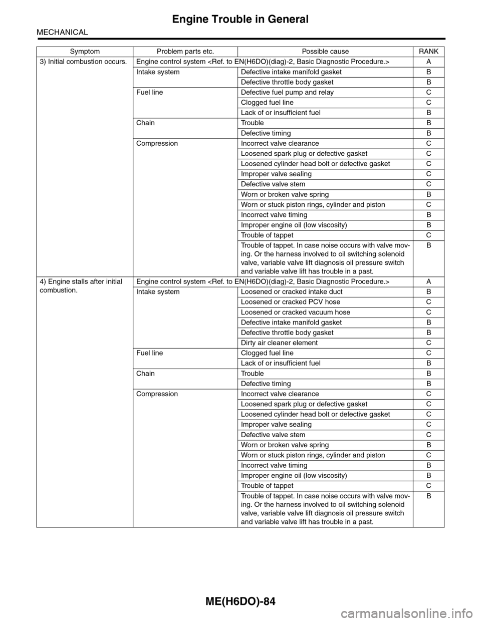
Engine Trouble in General
MECHANICAL
3) Initial combustion occurs. Engine control system
Intake system Defective intake manifold gasket B
Defective throttle body gasket B
Fuel line Defective fuel pump and relay C
Clogged fuel line C
Lack of or insufficient fuel B
Chain Trouble B
Defective timing B
Compression Incorrect valve clearance C
Loosened spark plug or defective gasket C
Loosened cylinder head bolt or defective gasket C
Improper valve sealing C
Defective valve stem C
Wor n or broken valve spr ing B
Wor n or stuck piston r ings, cylinder and piston C
Incorrect valve timing B
Improper engine oil (low viscosity) B
Tr o u b l e o f t a p p e t C
Tr o u b l e o f t a p p e t . I n c a s e n o i s e o c c u r s w i t h v a l v e m o v -
ing. Or the harness involved to oil switching solenoid
valve, variable valve lift diagnosis oil pressure switch
and variable valve lift has trouble in a past.
B
4) Engine stalls after initial
combustion.
Engine control system
Intake system Loosened or cracked intake duct B
Loosened or cracked PCV hose C
Loosened or cracked vacuum hose C
Defective intake manifold gasket B
Defective throttle body gasket B
Dirty air cleaner element C
Fuel line Clogged fuel line C
Lack of or insufficient fuel B
Chain Trouble B
Defective timing B
Compression Incorrect valve clearance C
Loosened spark plug or defective gasket C
Loosened cylinder head bolt or defective gasket C
Improper valve sealing C
Defective valve stem C
Wor n or broken valve spr ing B
Wor n or stuck piston r ings, cylinder and piston C
Incorrect valve timing B
Improper engine oil (low viscosity) B
Tr o u b l e o f t a p p e t C
Tr o u b l e o f t a p p e t . I n c a s e n o i s e o c c u r s w i t h v a l v e m o v -
ing. Or the harness involved to oil switching solenoid
valve, variable valve lift diagnosis oil pressure switch
and variable valve lift has trouble in a past.
B
Symptom Problem parts etc. Possible cause RANK