SUBARU TRIBECA 2009 1.G Service Workshop Manual
Manufacturer: SUBARU, Model Year: 2009, Model line: TRIBECA, Model: SUBARU TRIBECA 2009 1.GPages: 2453, PDF Size: 46.32 MB
Page 1961 of 2453
SC(H6DO)-3
General Description
STARTING/CHARGING SYSTEMS
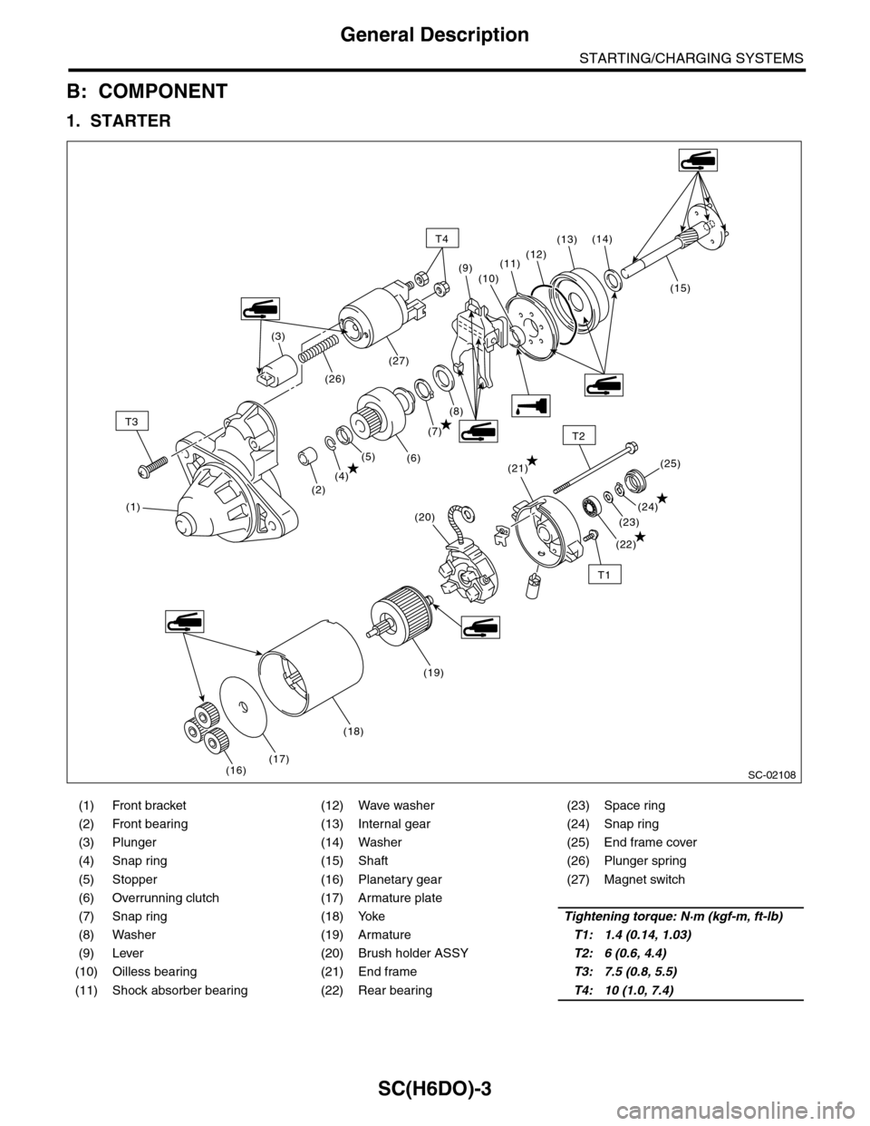
B: COMPONENT
1. STARTER
(1) Front bracket (12) Wave washer (23) Space ring
(2) Front bearing (13) Internal gear (24) Snap ring
(3) Plunger (14) Washer (25) End frame cover
(4) Snap ring (15) Shaft (26) Plunger spring
(5) Stopper (16) Planetary gear (27) Magnet switch
(6) Overrunning clutch (17) Armature plate
(7) Snap ring (18) YokeTightening torque: N·m (kgf-m, ft-lb)
(8) Washer (19) ArmatureT1: 1.4 (0.14, 1.03)
(9) Lever (20) Brush holder ASSYT2: 6 (0.6, 4.4)
(10) Oilless bearing (21) End frameT3: 7.5 (0.8, 5.5)
(11) Shock absorber bearing (22) Rear bearingT4: 10 (1.0, 7.4)
SC-02108
T3
T1
T2
(1)
(2)
T4
(4)(21)
(22)
(23)
(24)
(25)(5)(6)
(7)
(8)
(15)
(14)(13)
(12)(11)
(10)(9)
(3)
(26)
(27)
(16)(17)
(18)
(19)
(20)
Page 1962 of 2453
SC(H6DO)-4
General Description
STARTING/CHARGING SYSTEMS
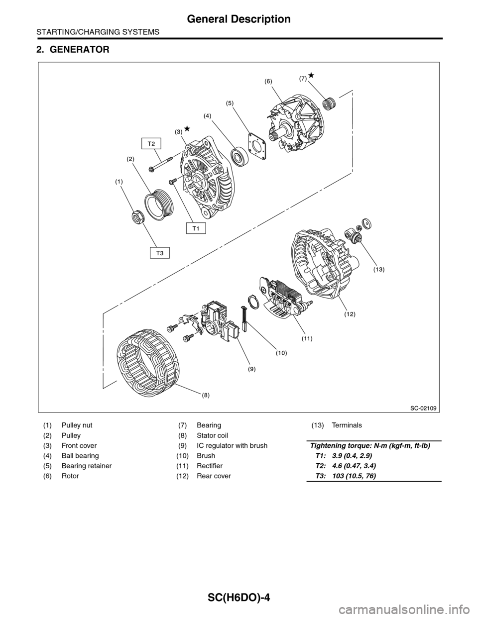
2. GENERATOR
(1) Pulley nut (7) Bearing (13) Terminals
(2) Pulley (8) Stator coil
(3) Front cover (9) IC regulator with brushTightening torque: N·m (kgf-m, ft-lb)
(4) Ball bearing (10) BrushT1: 3.9 (0.4, 2.9)
(5) Bearing retainer (11) RectifierT2: 4.6 (0.47, 3.4)
(6) Rotor (12) Rear coverT3: 103 (10.5, 76)
Page 1963 of 2453
SC(H6DO)-5
General Description
STARTING/CHARGING SYSTEMS
C: CAUTION
•Wear work clothing, including a cap, protective
goggles and protective shoes during operation.
•Remove contamination including dirt and corro-
sion before removal, installation or disassembly.
•Keep the disassembled parts in order and pro-
tect them from dust and dirt.
•Before removal, installation or disassembly, be
sure to clarify the failure. Avoid unnecessary re-
moval, installation, disassembly and replacement.
•Be careful not to burn yourself, because each
part on the vehicle is hot after running.
•Be sure to tighten fasteners including bolts and
nuts to the specified torque.
•Place shop jacks or rigid racks at the specified
points.
•Before disconnecting connectors of sensors or
units, be sure to disconnect the ground cable from
battery.
Page 1964 of 2453
SC(H6DO)-6
Starter
STARTING/CHARGING SYSTEMS
2. Starter
A: REMOVAL
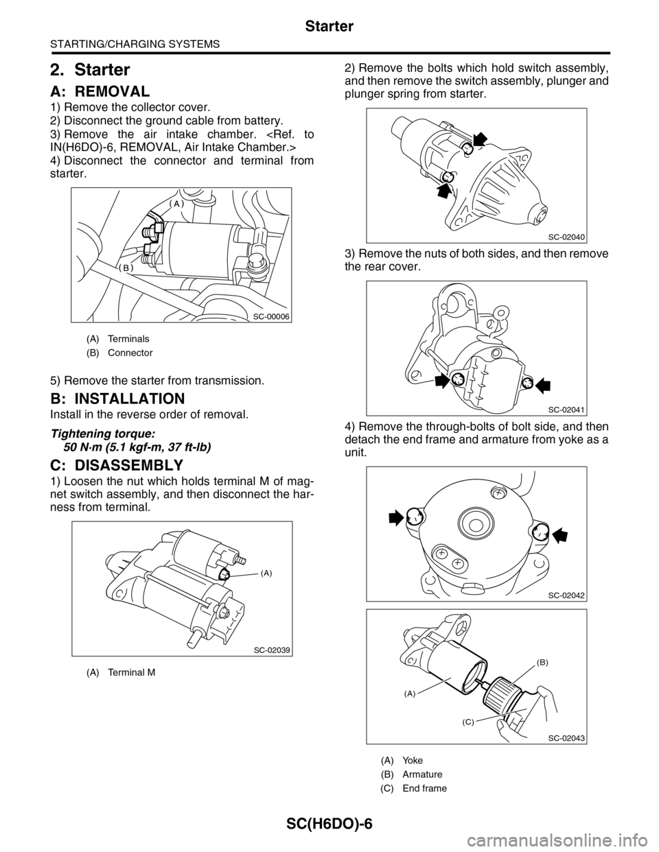
1) Remove the collector cover.
2) Disconnect the ground cable from battery.
3) Remove the air intake chamber.
4) Disconnect the connector and terminal from
starter.
5) Remove the starter from transmission.
B: INSTALLATION
Install in the reverse order of removal.
Tightening torque:
50 N·m (5.1 kgf-m, 37 ft-lb)
C: DISASSEMBLY
1) Loosen the nut which holds terminal M of mag-
net switch assembly, and then disconnect the har-
ness from terminal.
2) Remove the bolts which hold switch assembly,
and then remove the switch assembly, plunger and
plunger spring from starter.
3) Remove the nuts of both sides, and then remove
the rear cover.
4) Remove the through-bolts of bolt side, and then
detach the end frame and armature from yoke as a
unit.
(A) Terminals
(B) Connector
(A) Terminal M
SC-00006
(A)
SC-02039
(A) Yoke
(B) Armature
(C) End frame
SC-02040
SC-02041
SC-02042
SC-02043
(A)
(C)
(B)
Page 1965 of 2453
SC(H6DO)-7
Starter
STARTING/CHARGING SYSTEMS
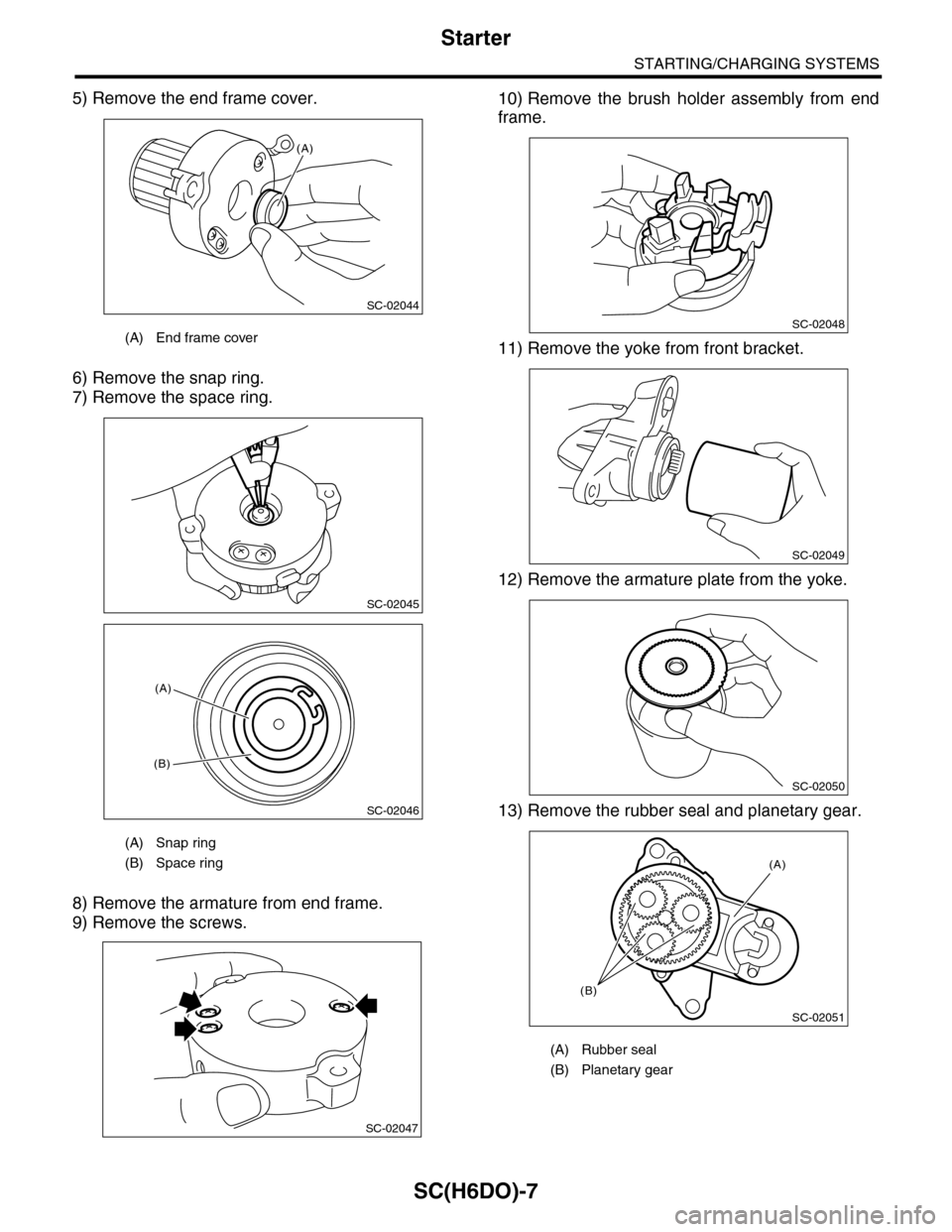
5) Remove the end frame cover.
6) Remove the snap ring.
7) Remove the space ring.
8) Remove the armature from end frame.
9) Remove the screws.
10) Remove the brush holder assembly from end
frame.
11) Remove the yoke from front bracket.
12) Remove the armature plate from the yoke.
13) Remove the rubber seal and planetary gear.
(A) End frame cover
(A) Snap ring
(B) Space ring
(A)
SC-02044
SC-02045
SC-02046
(A)
(B)
SC-02047
(A) Rubber seal
(B) Planetary gear
SC-02048
SC-02049
SC-02050
SC-02051
(A)
(B)
Page 1966 of 2453
SC(H6DO)-8
Starter
STARTING/CHARGING SYSTEMS
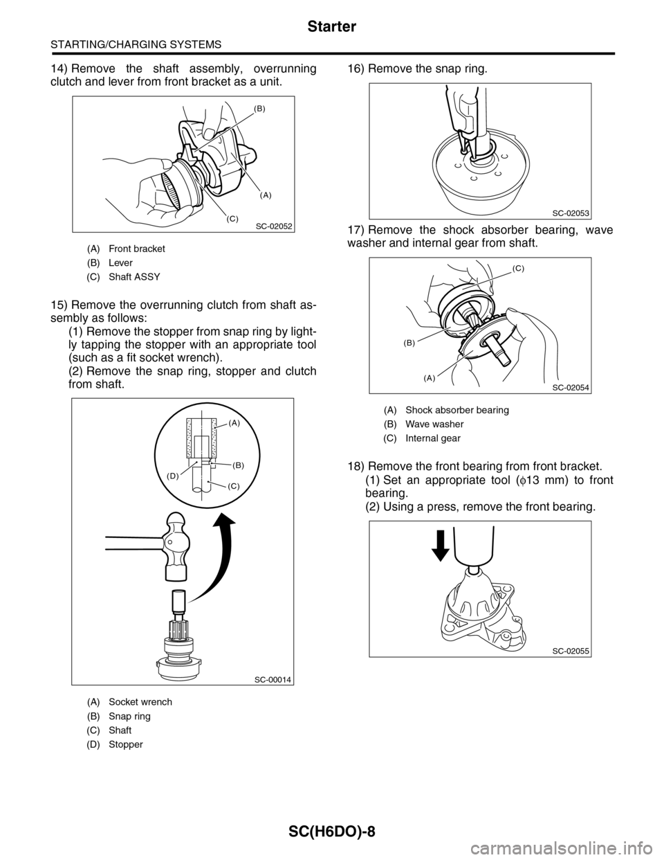
14) Remove the shaft assembly, overrunning
clutch and lever from front bracket as a unit.
15) Remove the overrunning clutch from shaft as-
sembly as follows:
(1) Remove the stopper from snap ring by light-
ly tapping the stopper with an appropriate tool
(such as a fit socket wrench).
(2) Remove the snap ring, stopper and clutch
from shaft.
16) Remove the snap ring.
17) Remove the shock absorber bearing, wave
washer and internal gear from shaft.
18) Remove the front bearing from front bracket.
(1) Set an appropriate tool (φ13 mm) to front
bearing.
(2) Using a press, remove the front bearing.
(A) Front bracket
(B) Lever
(C) Shaft ASSY
(A) Socket wrench
(B) Snap ring
(C) Shaft
(D) Stopper
SC-02052
(B)
(A)
(C)
SC-00014
(A)
(B)
(C)(D)
(A) Shock absorber bearing
(B) Wave washer
(C) Internal gear
SC-02053
SC-02054
(C)
(A)
(B)
SC-02055
Page 1967 of 2453
SC(H6DO)-9
Starter
STARTING/CHARGING SYSTEMS
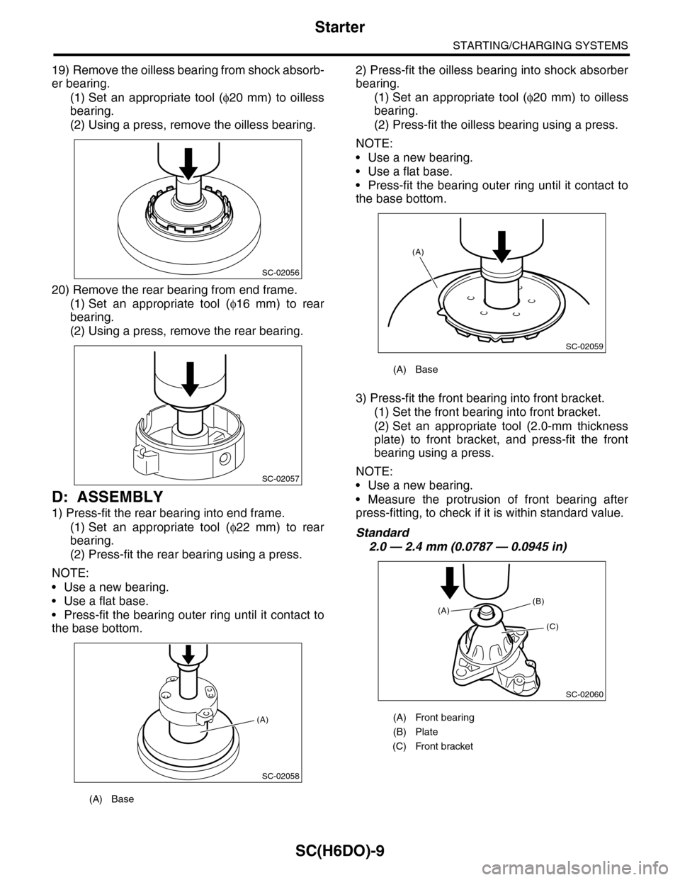
19) Remove the oilless bearing from shock absorb-
er bearing.
(1) Set an appropriate tool (φ20 mm) to oilless
bearing.
(2) Using a press, remove the oilless bearing.
20) Remove the rear bearing from end frame.
(1) Set an appropriate tool (φ16 mm) to rear
bearing.
(2) Using a press, remove the rear bearing.
D: ASSEMBLY
1) Press-fit the rear bearing into end frame.
(1) Set an appropriate tool (φ22 mm) to rear
bearing.
(2) Press-fit the rear bearing using a press.
NOTE:
•Use a new bearing.
•Use a flat base.
•Press-fit the bearing outer ring until it contact to
the base bottom.
2) Press-fit the oilless bearing into shock absorber
bearing.
(1) Set an appropriate tool (φ20 mm) to oilless
bearing.
(2) Press-fit the oilless bearing using a press.
NOTE:
•Use a new bearing.
•Use a flat base.
•Press-fit the bearing outer ring until it contact to
the base bottom.
3) Press-fit the front bearing into front bracket.
(1) Set the front bearing into front bracket.
(2) Set an appropriate tool (2.0-mm thickness
plate) to front bracket, and press-fit the front
bearing using a press.
NOTE:
•Use a new bearing.
•Measure the protrusion of front bearing after
press-fitting, to check if it is within standard value.
Standard
2.0 — 2.4 mm (0.0787 — 0.0945 in)
(A) Base
SC-02056
SC-02057
SC-02058
(A)
(A) Base
(A) Front bearing
(B) Plate
(C) Front bracket
SC-02059
(A)
SC-02060
(B)
(C)
(A)
Page 1968 of 2453
SC(H6DO)-10
Starter
STARTING/CHARGING SYSTEMS
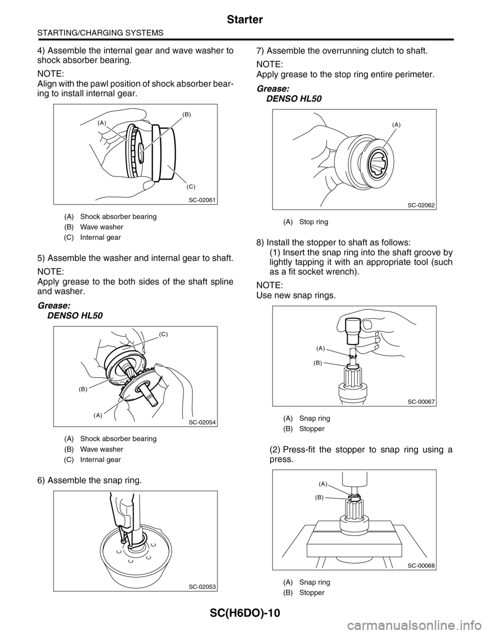
4) Assemble the internal gear and wave washer to
shock absorber bearing.
NOTE:
Align with the pawl position of shock absorber bear-
ing to install internal gear.
5) Assemble the washer and internal gear to shaft.
NOTE:
Apply grease to the both sides of the shaft spline
and washer.
Grease:
DENSO HL50
6) Assemble the snap ring.
7) Assemble the overrunning clutch to shaft.
NOTE:
Apply grease to the stop ring entire perimeter.
Grease:
DENSO HL50
8) Install the stopper to shaft as follows:
(1) Insert the snap ring into the shaft groove by
lightly tapping it with an appropriate tool (such
as a fit socket wrench).
NOTE:
Use new snap rings.
(2) Press-fit the stopper to snap ring using a
press.
(A) Shock absorber bearing
(B) Wave washer
(C) Internal gear
(A) Shock absorber bearing
(B) Wave washer
(C) Internal gear
SC-02061
(A)
(B)
(C)
SC-02054
(C)
(A)
(B)
SC-02053
(A) Stop ring
(A) Snap ring
(B) Stopper
(A) Snap ring
(B) Stopper
SC-02062
(A)
SC-00067
(B)
(A)
SC-00068
(A)
(B)
Page 1969 of 2453
SC(H6DO)-11
Starter
STARTING/CHARGING SYSTEMS
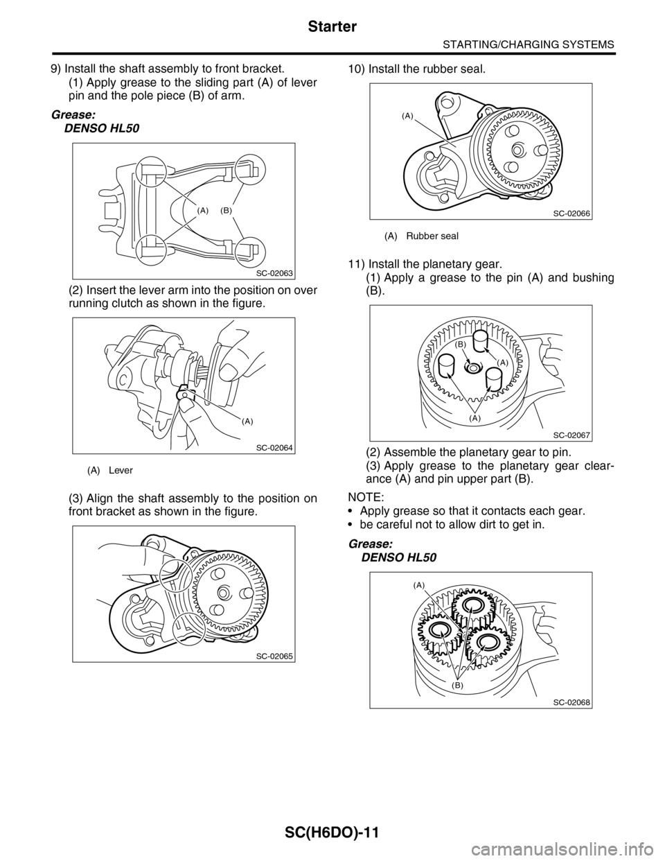
9) Install the shaft assembly to front bracket.
(1) Apply grease to the sliding part (A) of lever
pin and the pole piece (B) of arm.
Grease:
DENSO HL50
(2) Insert the lever arm into the position on over
running clutch as shown in the figure.
(3) Align the shaft assembly to the position on
front bracket as shown in the figure.
10) Install the rubber seal.
11) Install the planetary gear.
(1) Apply a grease to the pin (A) and bushing
(B).
(2) Assemble the planetary gear to pin.
(3) Apply grease to the planetary gear clear-
ance (A) and pin upper part (B).
NOTE:
•Apply grease so that it contacts each gear.
•be careful not to allow dirt to get in.
Grease:
DENSO HL50
(A) Lever
SC-02063
(A) (B)
SC-02064
(A)
SC-02065
(A) Rubber seal
SC-02066
(A)
SC-02067
(B)
(A)
(A)
SC-02068
(B)
(A)(A)
Page 1970 of 2453
SC(H6DO)-12
Starter
STARTING/CHARGING SYSTEMS
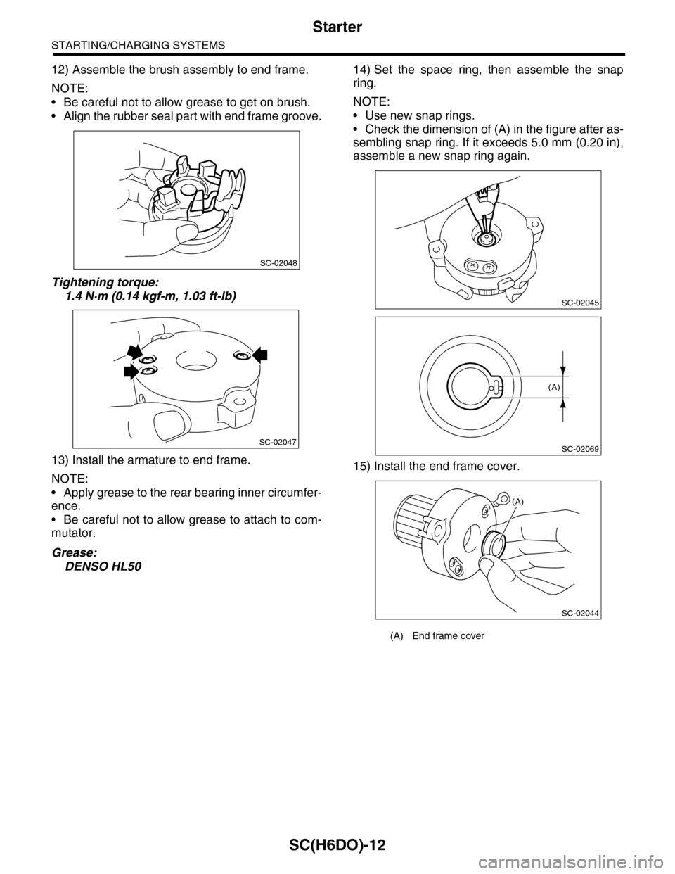
12) Assemble the brush assembly to end frame.
NOTE:
•Be careful not to allow grease to get on brush.
•Align the rubber seal part with end frame groove.
Tightening torque:
1.4 N·m (0.14 kgf-m, 1.03 ft-lb)
13) Install the armature to end frame.
NOTE:
•Apply grease to the rear bearing inner circumfer-
ence.
•Be careful not to allow grease to attach to com-
mutator.
Grease:
DENSO HL50
14) Set the space ring, then assemble the snap
ring.
NOTE:
•Use new snap rings.
•Check the dimension of (A) in the figure after as-
sembling snap ring. If it exceeds 5.0 mm (0.20 in),
assemble a new snap ring again.
15) Install the end frame cover.
SC-02048
SC-02047
(A) End frame cover
SC-02045
SC-02069
(A)
(A)
SC-02044