sensor SUBARU TRIBECA 2009 1.G Service Workshop Manual
[x] Cancel search | Manufacturer: SUBARU, Model Year: 2009, Model line: TRIBECA, Model: SUBARU TRIBECA 2009 1.GPages: 2453, PDF Size: 46.32 MB
Page 1083 of 2453
VDC-2
General Description
VEHICLE DYNAMICS CONTROL (VDC)
1. General Description
A: SPECIFICATION
B: COMPONENT
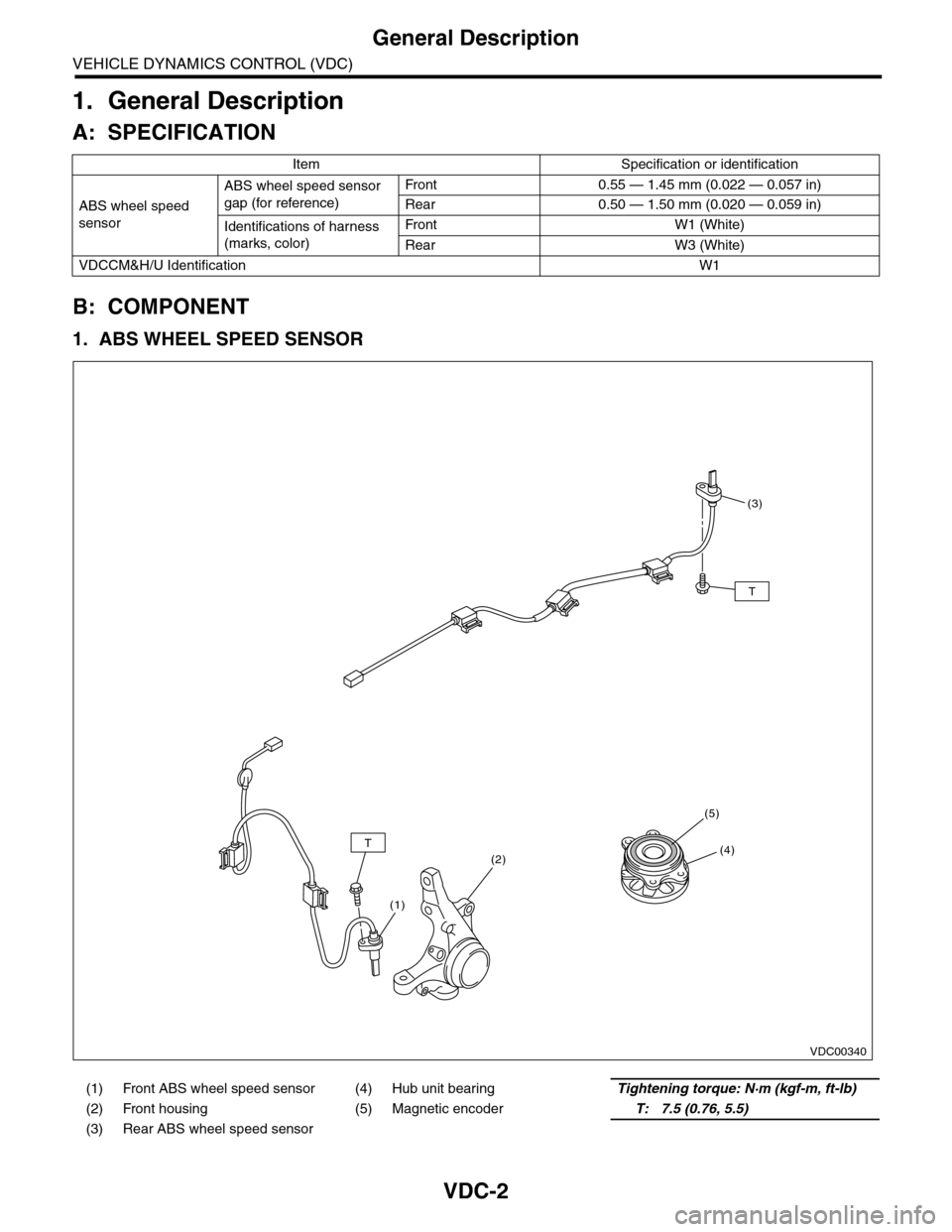
1. ABS WHEEL SPEED SENSOR
Item Specification or identification
ABS wheel speed
sensor
ABS wheel speed sensor
gap (for reference)
Fr o nt 0 . 55 — 1. 4 5 m m ( 0. 0 2 2 — 0. 0 57 i n)
Rear 0.50 — 1.50 mm (0.020 — 0.059 in)
Identifications of harness
(marks, color)
Fr o nt W1 ( Wh i te )
Rear W3 (White)
VDCCM&H/U IdentificationW1
(1) Front ABS wheel speed sensor (4) Hub unit bearingTightening torque: N·m (kgf-m, ft-lb)
(2) Front housing (5) Magnetic encoderT: 7.5 (0.76, 5.5)
(3) Rear ABS wheel speed sensor
VDC00340
T
T
(3)
(4)
(5)
(2)
(1)
Page 1084 of 2453
VDC-3
General Description
VEHICLE DYNAMICS CONTROL (VDC)
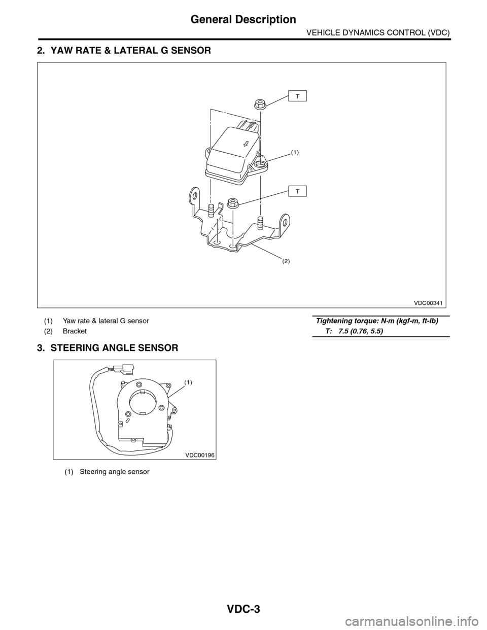
2. YAW RATE & LATERAL G SENSOR
3. STEERING ANGLE SENSOR
(1) Yaw rate & lateral G sensor Tightening torque: N·m (kgf-m, ft-lb)
(2) Bracket T: 7.5 (0.76, 5.5)
VDC00341
(1)
T
T
(2)
(1) Steering angle sensor
VDC00196
(1)
Page 1086 of 2453
VDC-5
General Description
VEHICLE DYNAMICS CONTROL (VDC)
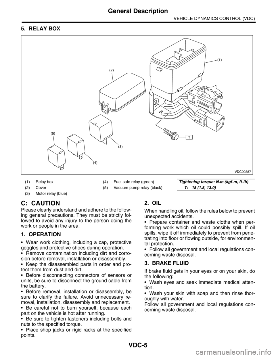
5. RELAY BOX
C: CAUTION
Please clearly understand and adhere to the follow-
ing general precautions. They must be strictly fol-
lowed to avoid any injury to the person doing the
work or people in the area.
1. OPERATION
•Wear work clothing, including a cap, protective
goggles and protective shoes during operation.
•Remove contamination including dirt and corro-
sion before removal, installation or disassembly.
•Keep the disassembled parts in order and pro-
tect them from dust and dirt.
•Before disconnecting connectors of sensors or
units, be sure to disconnect the ground cable from
the battery.
•Before removal, installation or disassembly, be
sure to clarify the failure. Avoid unnecessary re-
moval, installation, disassembly and replacement.
•Be careful not to burn yourself, because each
part on the vehicle is hot after running.
•Be sure to tighten fasteners including bolts and
nuts to the specified torque.
•Place shop jacks or rigid racks at the specified
points.
2. OIL
When handling oil, follow the rules below to prevent
unexpected accidents.
•Prepare container and waste cloths when per-
forming work which oil could possibly spill. If oil
spills, wipe it off immediately to prevent from pene-
trating into floor or flowing outside, for environmen-
tal protection.
•Follow all government and local regulations con-
cerning waste disposal.
3. BRAKE FLUID
If brake fluid gets in your eyes or on your skin, do
the following:
•Wash eyes and seek immediate medical atten-
tion.
•Wash your skin with soap and then rinse thor-
oughly with water.
Follow all government and local regulations con-
cerning waste disposal.
(1) Relay box (4) Fuel safe relay (green)Tightening torque: N·m (kgf-m, ft-lb)
(2) Cover (5) Vacuum pump relay (black)T: 18 (1.8, 13.0)
(3) Motor relay (blue)
Page 1087 of 2453
VDC-6
General Description
VEHICLE DYNAMICS CONTROL (VDC)
D: PREPARATION TOOL
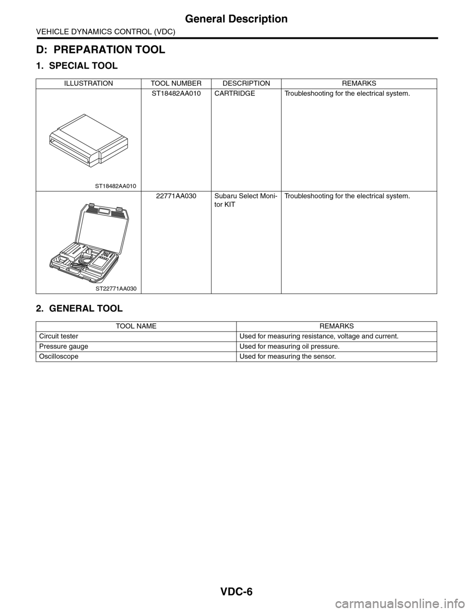
1. SPECIAL TOOL
2. GENERAL TOOL
ILLUSTRATION TOOL NUMBER DESCRIPTION REMARKS
ST18482AA010 CARTRIDGE Troubleshooting for the electrical system.
22771AA030 Subaru Select Moni-
tor KIT
Tr o u b l e s h o o t i n g f o r t h e e l e c t r i c a l s y s t e m .
TOOL NAME REMARKS
Circuit tester Used for measuring resistance, voltage and current.
Pressure gauge Used for measuring oil pressure.
Oscilloscope Used for measuring the sensor.
ST18482AA010
ST22771AA030
Page 1092 of 2453
VDC-11
VDC Control Module & Hydraulic Control Unit (VDCCM&H/U)
VEHICLE DYNAMICS CONTROL (VDC)
D: ADJUSTMENT
When the following replacement, removal and in-
stallation are performed, be sure to perform center-
ing of the steering angle sensor and zero point
setting of the yaw rate & G sensor.
•VDCCM&H/U
•Steering angle sensor
•Yaw rate & lateral G sensor
•Steering wheel parts (Including airbag)
•Suspension parts
•Wheel alignment adjustment
1) Park the vehicle straight on a level surface. (En-
gine operation in the “P” or “N” range)
2) Check that steering wheel is positioned at the
center. (When the center position is not correct, ad-
just the wheel alignment.)
3) Set the Subaru Select Monitor to the vehicle,
and select {Set up mode for Neutral of Steering An-
gle Sensor & Lateral G Sensor 0 point} in the
“Function check sequence” screen. (Follow the
procedures shown in the display.)
4) On the “Brake Control System” display screen,
select {Current Data Display & Save}, and check
that the steering angle sensor shows “0 deg”.
5) When the “0 deg” is not displayed, repeat the
above steps and check that the “0 deg” is dis-
played.
6) Drive the vehicle for 10 minutes, and check that
the ABS and VDC warning light is not illuminated.
7) Check that there is no unnecessary VDC opera-
tion or steering control loss. If there is a problem,
repeat the steps above.
Page 1099 of 2453
VDC-18
Yaw Rate & Lateral G Sensor
VEHICLE DYNAMICS CONTROL (VDC)
5. Yaw Rate & Lateral G Sensor
A: REMOVAL
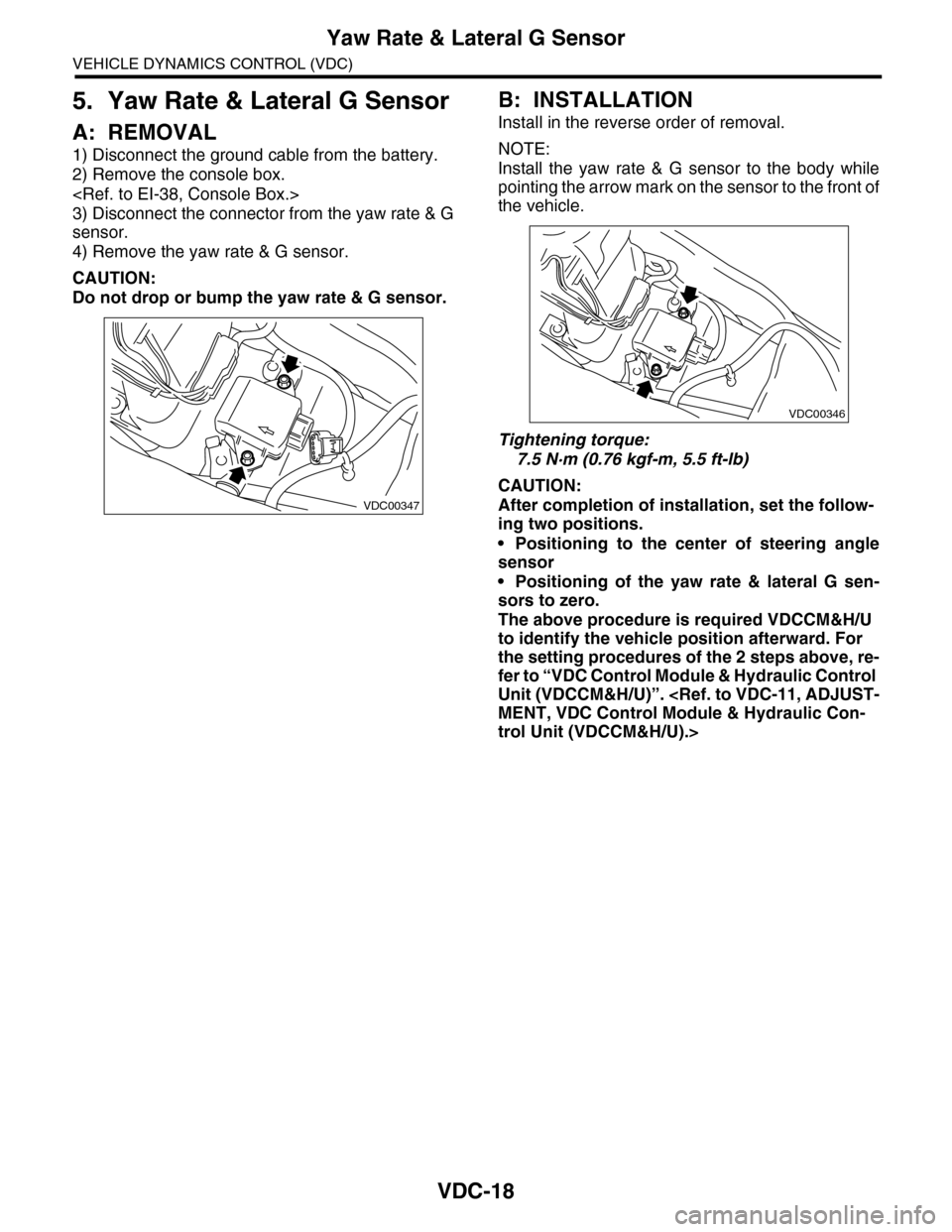
1) Disconnect the ground cable from the battery.
2) Remove the console box.
3) Disconnect the connector from the yaw rate & G
sensor.
4) Remove the yaw rate & G sensor.
CAUTION:
Do not drop or bump the yaw rate & G sensor.
B: INSTALLATION
Install in the reverse order of removal.
NOTE:
Install the yaw rate & G sensor to the body while
pointing the arrow mark on the sensor to the front of
the vehicle.
Tightening torque:
7.5 N·m (0.76 kgf-m, 5.5 ft-lb)
CAUTION:
After completion of installation, set the follow-
ing two positions.
•Positioning to the center of steering angle
sensor
•Positioning of the yaw rate & lateral G sen-
sors to zero.
The above procedure is required VDCCM&H/U
to identify the vehicle position afterward. For
the setting procedures of the 2 steps above, re-
fer to “VDC Control Module & Hydraulic Control
Unit (VDCCM&H/U)”.
trol Unit (VDCCM&H/U).>
VDC00347
VDC00346
Page 1100 of 2453
VDC-19
Steering Angle Sensor
VEHICLE DYNAMICS CONTROL (VDC)
6. Steering Angle Sensor
A: REPLACEMENT
CAUTION:
•Do not perform the removal except when the
replacement.
•When replacing more than three times, re-
place the combination switch as assembly to
protect the threads.
1) Set the steering wheel in a straight-ahead posi-
tion.
2) Disconnect the ground cable from the battery.
3) Remove the airbag module.
WARNING:
Always refer to “Airbag System” when perform-
ing the airbag module repair service.
4) Remove the steering wheel.
5) Remove the screws and remove the steering
column lower cover.
6) Remove the two screws securing the steering
column upper cover.
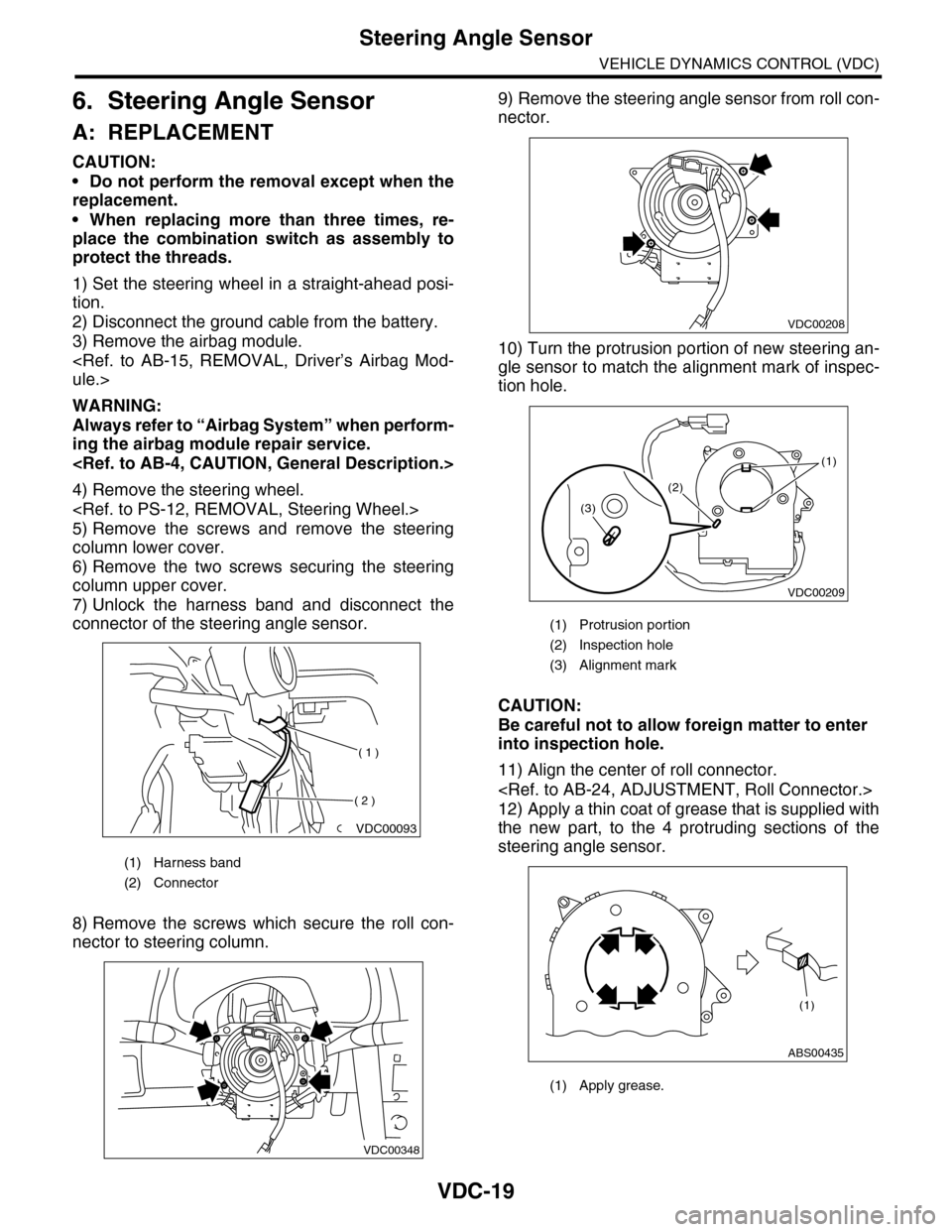
7) Unlock the harness band and disconnect the
connector of the steering angle sensor.
8) Remove the screws which secure the roll con-
nector to steering column.
9) Remove the steering angle sensor from roll con-
nector.
10) Turn the protrusion portion of new steering an-
gle sensor to match the alignment mark of inspec-
tion hole.
CAUTION:
Be careful not to allow foreign matter to enter
into inspection hole.
11) Align the center of roll connector.
12) Apply a thin coat of grease that is supplied with
the new part, to the 4 protruding sections of the
steering angle sensor.
(1) Harness band
(2) Connector
VDC00093
( 1 )
( 2 )
VDC00348
(1) Protrusion portion
(2) Inspection hole
(3) Alignment mark
(1) Apply grease.
VDC00208
VDC00209
(1)
(2)
(3)
ABS00435
(1)
Page 1101 of 2453
VDC-20
Steering Angle Sensor
VEHICLE DYNAMICS CONTROL (VDC)
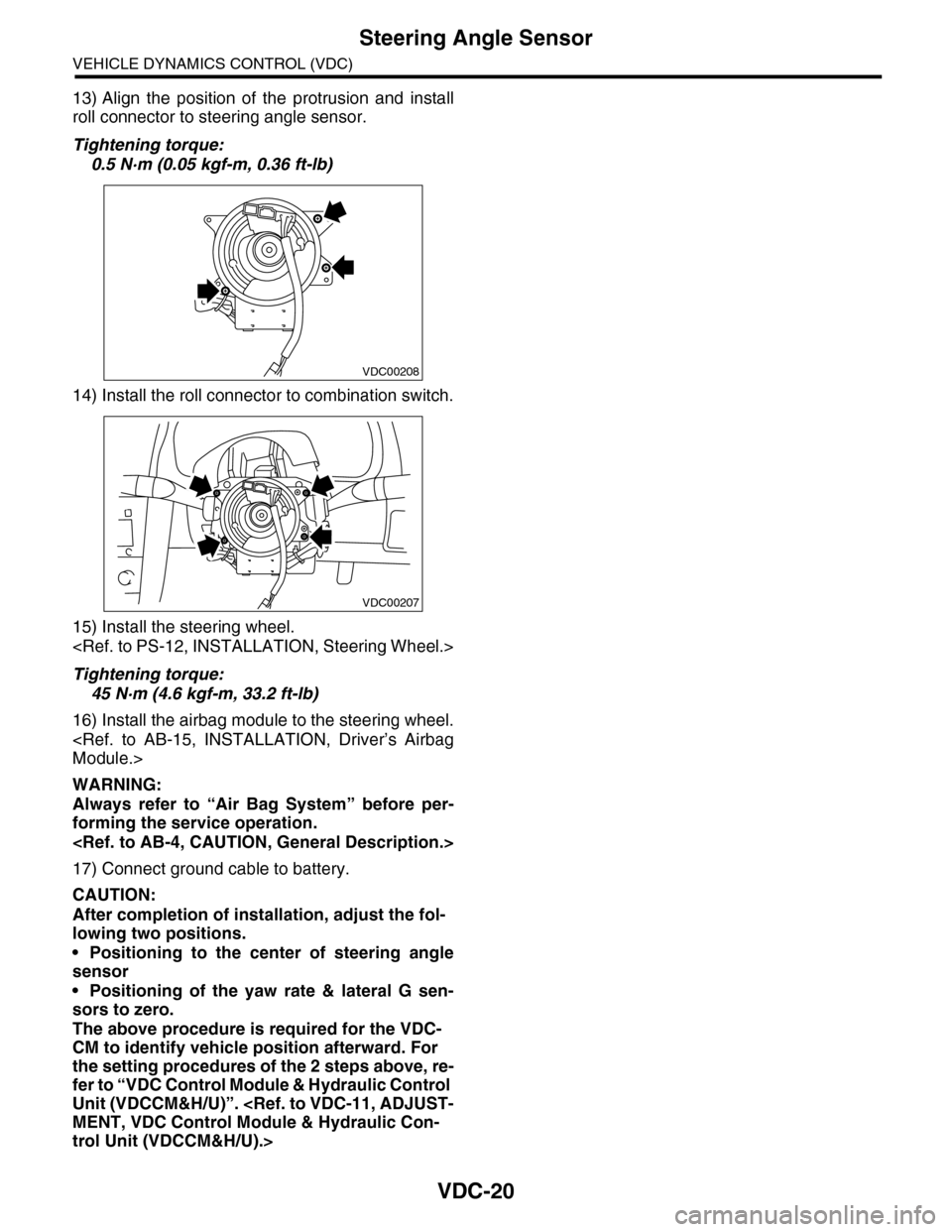
13) Align the position of the protrusion and install
roll connector to steering angle sensor.
Tightening torque:
0.5 N·m (0.05 kgf-m, 0.36 ft-lb)
14) Install the roll connector to combination switch.
15) Install the steering wheel.
Tightening torque:
45 N·m (4.6 kgf-m, 33.2 ft-lb)
16) Install the airbag module to the steering wheel.
WARNING:
Always refer to “Air Bag System” before per-
forming the service operation.
17) Connect ground cable to battery.
CAUTION:
After completion of installation, adjust the fol-
lowing two positions.
•Positioning to the center of steering angle
sensor
•Positioning of the yaw rate & lateral G sen-
sors to zero.
The above procedure is required for the VDC-
CM to identify vehicle position afterward. For
the setting procedures of the 2 steps above, re-
fer to “VDC Control Module & Hydraulic Control
Unit (VDCCM&H/U)”.
trol Unit (VDCCM&H/U).>
VDC00208
VDC00207
Page 1102 of 2453
VDC-21
Front ABS Wheel Speed Sensor
VEHICLE DYNAMICS CONTROL (VDC)
7. Front ABS Wheel Speed Sen-
sor
A: REMOVAL
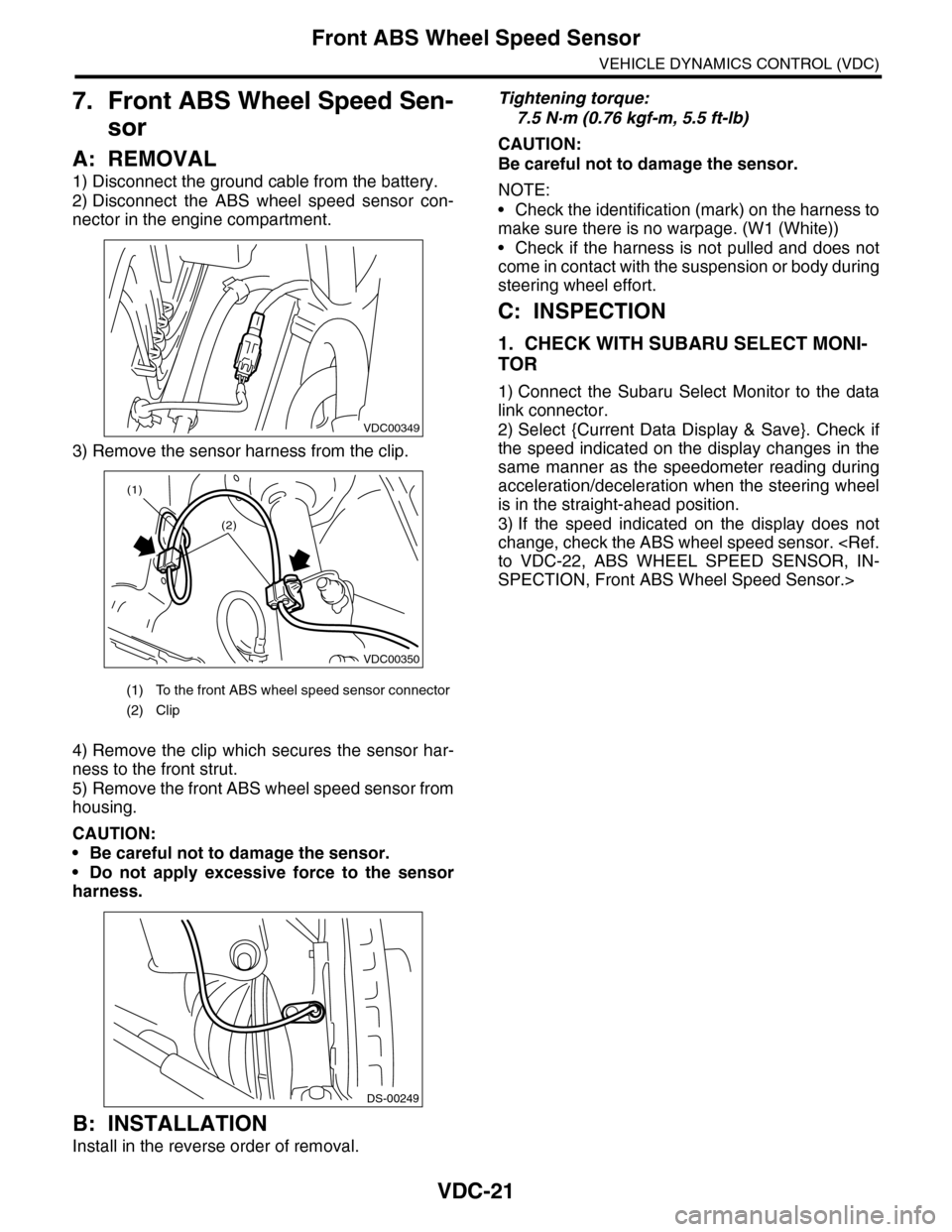
1) Disconnect the ground cable from the battery.
2) Disconnect the ABS wheel speed sensor con-
nector in the engine compartment.
3) Remove the sensor harness from the clip.
4) Remove the clip which secures the sensor har-
ness to the front strut.
5) Remove the front ABS wheel speed sensor from
housing.
CAUTION:
•Be careful not to damage the sensor.
•Do not apply excessive force to the sensor
harness.
B: INSTALLATION
Install in the reverse order of removal.
Tightening torque:
7.5 N·m (0.76 kgf-m, 5.5 ft-lb)
CAUTION:
Be careful not to damage the sensor.
NOTE:
•Check the identification (mark) on the harness to
make sure there is no warpage. (W1 (White))
•Check if the harness is not pulled and does not
come in contact with the suspension or body during
steering wheel effort.
C: INSPECTION
1. CHECK WITH SUBARU SELECT MONI-
TOR
1) Connect the Subaru Select Monitor to the data
link connector.
2) Select {Current Data Display & Save}. Check if
the speed indicated on the display changes in the
same manner as the speedometer reading during
acceleration/deceleration when the steering wheel
is in the straight-ahead position.
3) If the speed indicated on the display does not
change, check the ABS wheel speed sensor.
SPECTION, Front ABS Wheel Speed Sensor.>
(1) To the front ABS wheel speed sensor connector
(2) Clip
VDC00349
VDC00350
(1)
(2)
DS-00249
Page 1103 of 2453
VDC-22
Front ABS Wheel Speed Sensor
VEHICLE DYNAMICS CONTROL (VDC)
2. ABS WHEEL SPEED SENSOR
1) Check the tip of the ABS wheel speed sensor for
foreign particles or damage. If necessary, clean the
tip or replace the ABS wheel speed sensor.
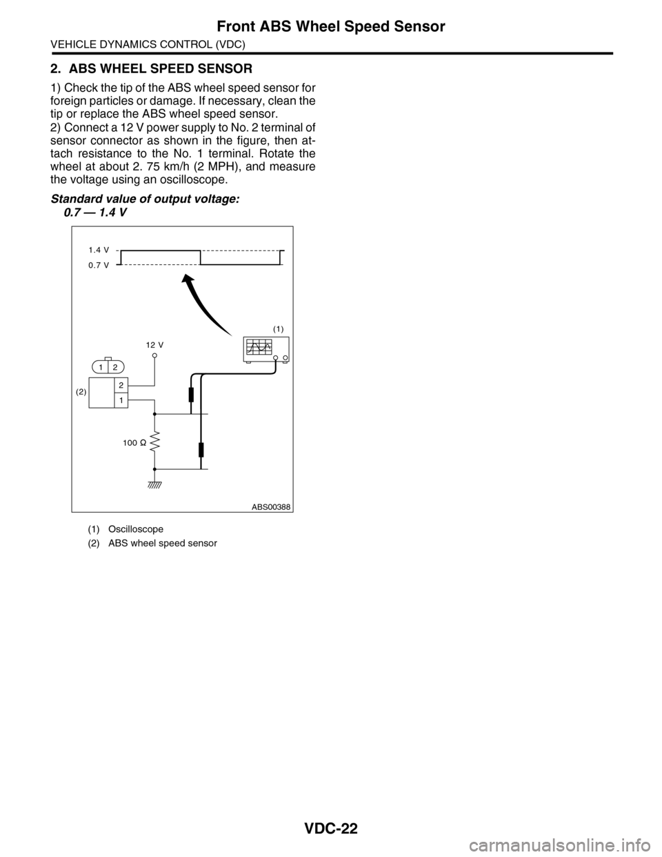
2) Connect a 12 V power supply to No. 2 terminal of
sensor connector as shown in the figure, then at-
tach resistance to the No. 1 terminal. Rotate the
wheel at about 2. 75 km/h (2 MPH), and measure
the voltage using an oscilloscope.
Standard value of output voltage:
0.7 — 1.4 V
(1) Oscilloscope
(2) ABS wheel speed sensor
ABS00388
(2)
(1)
100
1.4 V
0.7 V
12 V
2
1
12