sensor SUBARU TRIBECA 2009 1.G Service Workshop Manual
[x] Cancel search | Manufacturer: SUBARU, Model Year: 2009, Model line: TRIBECA, Model: SUBARU TRIBECA 2009 1.GPages: 2453, PDF Size: 46.32 MB
Page 1184 of 2453
EN(H6DO)(diag)-23
General Scan Tool
ENGINE (DIAGNOSTICS)
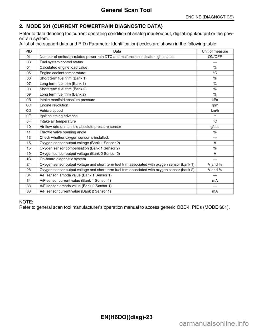
2. MODE $01 (CURRENT POWERTRAIN DIAGNOSTIC DATA)
Refer to data denoting the current operating condition of analog input/output, digital input/output or the pow-
ertrain system.
A list of the support data and PID (Parameter Identification) codes are shown in the following table.
NOTE:
Refer to general scan tool manufacturer’s operation manual to access generic OBD-II PIDs (MODE $01).
PID Data Unit of measure
01 Number of emission-related powertrain DTC and malfunction indicator light status ON/OFF
03 Fuel system control status—
04 Calculated engine load value%
05 Engine coolant temperature°C
06 Short term fuel trim (Bank 1)%
07 Long term fuel trim (Bank 1)%
08 Short term fuel trim (Bank 2)%
09 Long term fuel trim (Bank 2)%
0B Intake manifold absolute pressure kPa
0C Engine revolutionrpm
0D Vehicle speedkm/h
0E Ignition timing advance°
0F Intake air temperature°C
10 Air flow rate of manifold absolute pressure sensor g/sec
11 Throttle valve opening angle%
13 Check whether oxygen sensor is installed. —
15 Oxygen sensor output voltage (Bank 1 Sensor 2) V
15 Oxygen sensor compensation (Bank 1 Sensor 2) %
19 Oxygen sensor output voltage (Bank 2 Sensor 2) V
1C On-board diagnostic system—
24 Oxygen sensor output voltage and short term fuel trim associated with oxygen sensor (bank 1) V and %
28 Oxygen sensor output voltage and short term fuel trim associated with oxygen sensor (bank 2) V and %
34 A/F sensor lambda value (Bank 1 Sensor 1) —
34 A/F sensor current value (Bank 1 Sensor 1) mA
38 A/F sensor lambda value (Bank 2 Sensor 1) —
38 A/F sensor current value (Bank 2 Sensor 1) mA
Page 1185 of 2453
EN(H6DO)(diag)-24
General Scan Tool
ENGINE (DIAGNOSTICS)
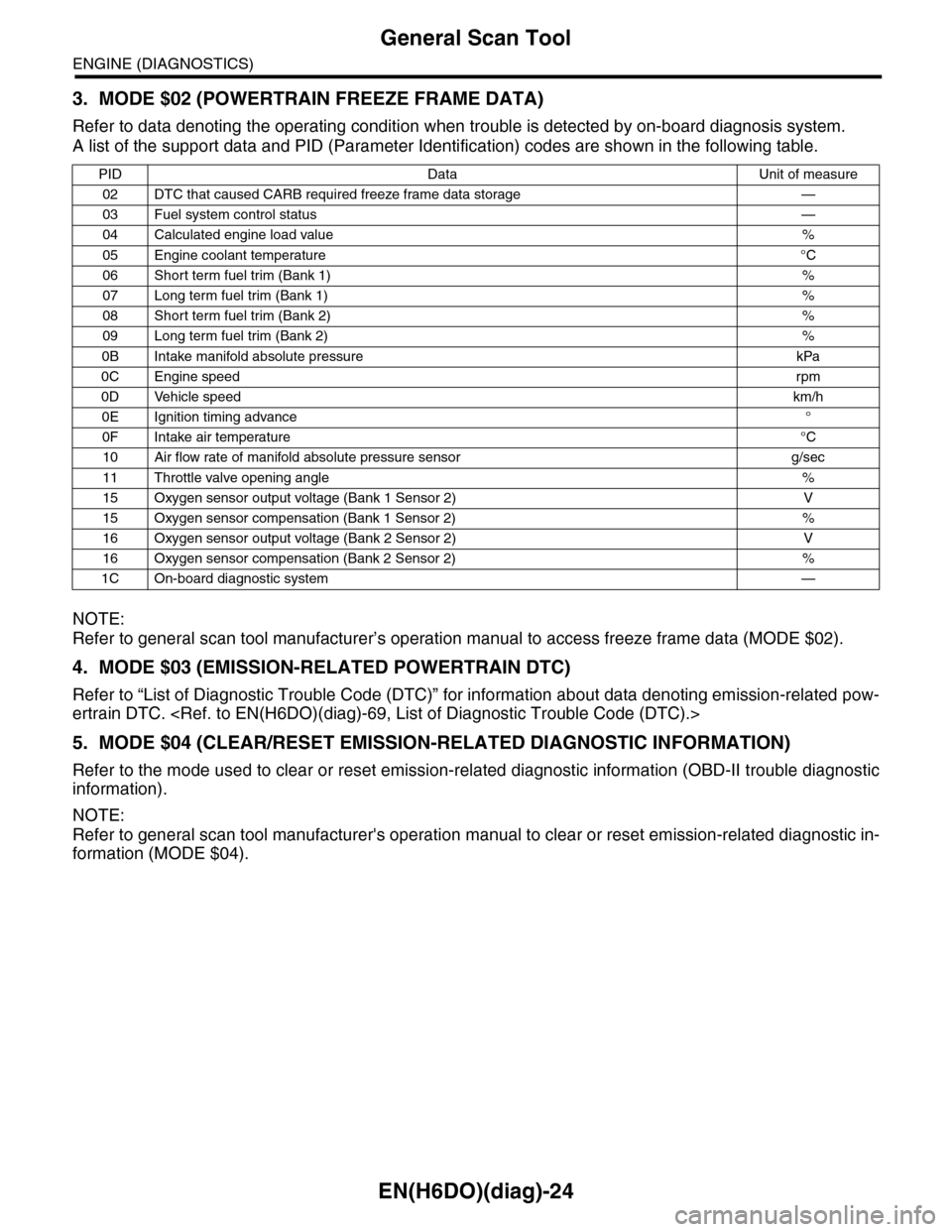
3. MODE $02 (POWERTRAIN FREEZE FRAME DATA)
Refer to data denoting the operating condition when trouble is detected by on-board diagnosis system.
A list of the support data and PID (Parameter Identification) codes are shown in the following table.
NOTE:
Refer to general scan tool manufacturer’s operation manual to access freeze frame data (MODE $02).
4. MODE $03 (EMISSION-RELATED POWERTRAIN DTC)
Refer to “List of Diagnostic Trouble Code (DTC)” for information about data denoting emission-related pow-
ertrain DTC.
5. MODE $04 (CLEAR/RESET EMISSION-RELATED DIAGNOSTIC INFORMATION)
Refer to the mode used to clear or reset emission-related diagnostic information (OBD-II trouble diagnostic
information).
NOTE:
Refer to general scan tool manufacturer's operation manual to clear or reset emission-related diagnostic in-
formation (MODE $04).
PID Data Unit of measure
02 DTC that caused CARB required freeze frame data storage —
03 Fuel system control status—
04 Calculated engine load value%
05 Engine coolant temperature°C
06 Short term fuel trim (Bank 1)%
07 Long term fuel trim (Bank 1)%
08 Short term fuel trim (Bank 2)%
09 Long term fuel trim (Bank 2)%
0B Intake manifold absolute pressure kPa
0C Engine speedrpm
0D Vehicle speedkm/h
0E Ignition timing advance°
0F Intake air temperature°C
10 Air flow rate of manifold absolute pressure sensor g/sec
11 Throttle valve opening angle%
15 Oxygen sensor output voltage (Bank 1 Sensor 2) V
15 Oxygen sensor compensation (Bank 1 Sensor 2) %
16 Oxygen sensor output voltage (Bank 2 Sensor 2) V
16 Oxygen sensor compensation (Bank 2 Sensor 2) %
1C On-board diagnostic system—
Page 1186 of 2453
EN(H6DO)(diag)-25
General Scan Tool
ENGINE (DIAGNOSTICS)
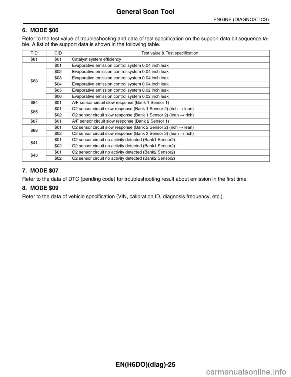
6. MODE $06
Refer to the test value of troubleshooting and data of test specification on the support data bit sequence ta-
ble. A list of the support data is shown in the following table.
7. MODE $07
Refer to the data of DTC (pending code) for troubleshooting result about emission in the first time.
8. MODE $09
Refer to the data of vehicle specification (VIN, calibration ID, diagnosis frequency, etc.).
TID CID Test value & Test specification
$81 $01 Catalyst system efficiency
$83
$01 Evaporative emission control system 0.04 inch leak
$02 Evaporative emission control system 0.04 inch leak
$03 Evaporative emission control system 0.04 inch leak
$04 Evaporative emission control system 0.04 inch leak
$05 Evaporative emission control system 0.02 inch leak
$06 Evaporative emission control system 0.02 inch leak
$84 $01 A/F sensor circuit slow response (Bank 1 Sensor 1)
$85$01 O2 sensor circuit slow response (Bank 1 Sensor 2) (rich → lean)
$02 O2 sensor circuit slow response (Bank 1 Sensor 2) (lean → rich)
$87 $01 A/F sensor circuit slow response (Bank 2 Sensor 1)
$88$01 O2 sensor circuit slow response (Bank 2 Sensor 2) (rich → lean)
$02 O2 sensor circuit slow response (Bank 2 Sensor 2) (lean → rich)
$41$01 O2 sensor circuit no activity detected (Bank1 Sensor2)
$02 O2 sensor circuit no activity detected (Bank1 Sensor2)
$43$01 O2 sensor circuit no activity detected (Bank2 Sensor2)
$02 O2 sensor circuit no activity detected (Bank2 Sensor2)
Page 1188 of 2453
![SUBARU TRIBECA 2009 1.G Service Workshop Manual EN(H6DO)(diag)-27
Subaru Select Monitor
ENGINE (DIAGNOSTICS)
4. READ CURRENT DATA FOR ENGINE (NORMAL MODE)
1) On the «Main Menu» display screen, select the {Each System Check} and press the [YES] ke SUBARU TRIBECA 2009 1.G Service Workshop Manual EN(H6DO)(diag)-27
Subaru Select Monitor
ENGINE (DIAGNOSTICS)
4. READ CURRENT DATA FOR ENGINE (NORMAL MODE)
1) On the «Main Menu» display screen, select the {Each System Check} and press the [YES] ke](/img/17/7322/w960_7322-1187.png)
EN(H6DO)(diag)-27
Subaru Select Monitor
ENGINE (DIAGNOSTICS)
4. READ CURRENT DATA FOR ENGINE (NORMAL MODE)
1) On the «Main Menu» display screen, select the {Each System Check} and press the [YES] key.
2) On the «System Selection Menu» display screen, select the {Engine} and press the [YES] key.
3) Press the [YES] key after the information of engine type has been displayed.
4) On the «Engine Diagnosis» display screen, select the {Current Data Display/Save}, and then press the
[YES] key.
5) On the «Data Display Menu» screen, select the {Data Display} and press the [YES] key.
6) Using the scroll key, scroll the display screen up or down until the desired data is shown.
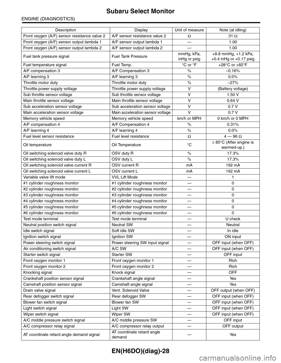
•A list of the support data is shown in the following table.
Description Display Unit of measure Note (at idling)
Engine load Engine load % 3.5%
Engine coolant temperature signal Coolant Temp. °C or °F≥ 75°C or 167°F (After
engine is warmed-up.)
A/F compensation 1 A/F Compensation 1 % 3.1%
A/F learning 1 A/F learning 1 % 0.0%
A/F compensation 2 A/F Compensation 2 % 4.7%
A/F learning 2 A/F learning 2 % 0.0%
Intake manifold absolute pressure Mani. Absolute PressuremmHg, kPa,
inHg or psig
200 — 300 mmHg, 26.7 —
40 kPa, 7.8 — 11.8 inHg or
3.8 — 5.8 psig
Engine speed signal Engine speed rpm 600 — 800 rpm
Meter vehicle speed signal Meter vehicle speed km/h or MPH 0 km/h or 0 MPH
Ignition timing signal Ignition timing deg 13 — 15 deg
Intake air temperature signal Intake air temperature °C or °F (Ambient air temperature)
Amount of intake air Mass Air Flow g/s or lb/m 3.8 g/s or 0.5 lb/m
Throttle opening angle signal Throttle valve angle % 1.2 — 1.6%
Fr o nt ox yg e n se n so r vo lt a g e val ue 1Fr o n t oxy ge n s en s or vol t ag e
value 1V0.035 V
Fr o nt ox yg e n se n so r vo lt a g e val ue 2Fr o n t oxy ge n s en s or vol t ag e
value 2V0.020 V
Battery voltage Battery Voltage V 12 — 14 V
Mass air flow voltage Mass air flow voltage V 1.1 — 1.2 V
Injection 1 pulse width Injection 1 pulse width ms 2.82 ms
Injection 2 pulse width Injection 2 pulse width ms 2.82 ms
Knock sensor compensation Knock correction deg 0 deg
Atmospheric pressure signal Atmospheric pressuremmHg, kPa,
inHg or psig(Atmospheric pressure)
Intake manifold relative pressureIntake manifold relative pres-
sure
mmHg, kPa,
inHg or psig
(Intake manifold absolute
pressure — atmospheric
pressure)
Acceleration opening angle signal Acceleration opening angle % 0%
Radiator fan output Radiator fan output % 0%
Purge control solenoid valve duty ratio CPC Duty % 0 — 3%
Generator duty ALT duty % 0%
Fuel pump duty Fuel pump duty % 33%
Va r i a b l e va l v e t i m i n g a d v a n c e a n g l e a m o u n t R V V T a d va n c e a n g l e a m o u n t R d e g 0 d e g
Va r i a b l e va l v e t i m i n g a d v a n c e a n g l e a m o u n t L V V T a d va n c e a n g l e a m o u n t L d e g 0 d e g
Oil flow control solenoid valve duty R OCV duty R % 9.4%
Oil flow control solenoid valve duty L OCV duty L % 9.4%
Oil flow control solenoid valve current R OCV current R mA 64 mA
Oil flow control solenoid valve current L OCV current L mA 64 mA
Fr o nt ox yg e n ( A / F) s en so r cu r r en t va l ue 1 A / F s en s or cu r r e nt va l ue 1 mA 0 . 0 m A
Fr o nt ox yg e n ( A / F) s en so r cu r r en t va l ue 2 A / F s en s or cu r r e nt va l ue 2 mA 0 . 0 m A
Fr o nt ox yg e n ( A / F) s en so r r es is t an ce val ue 1 A / F s en s or r e si st a nc e val u e 1Ω31 Ω
Page 1189 of 2453
EN(H6DO)(diag)-28
Subaru Select Monitor
ENGINE (DIAGNOSTICS)
Fr o nt ox yg e n ( A / F) s en so r r es is t an ce val ue 2 A / F s en s or r e si st a nc e val u e 2Ω31 Ω
Fr o nt ox yg e n ( A / F) s en so r ou t p ut la m bd a 1 A / F s en s or o ut p ut l am bd a 1 — 1 . 00
Fr o nt ox yg e n ( A / F) s en so r ou t p ut la m bd a 2 A / F s en s or o ut p ut l am bd a 2 — 1 . 00
Fuel tank pressure signal Fuel Tank PressuremmHg, kPa,
inHg or psig
+8.8 mmHg, +1.2 kPa,
+0.4 inHg or +0.17 psig
Fuel temperature signal Fuel Temp. °C or °F +28°C or +82°F
A/F compensation 3 A/F Compensation 3 % –0.16%
A/F learning 3 A/F learning 3 % 0.0%
Throttle motor duty Throttle motor duty % –27%
Throttle power supply voltage Throttle power supply voltage V (Battery voltage)
Sub throttle sensor voltage Sub throttle sensor voltage V 1.50 V
Main throttle sensor voltage Main throttle sensor voltage V 0.64 V
Sub acceleration sensor voltage Sub acceleration sensor voltage V 0.7 V
Main acceleration sensor voltage Main acceleration sensor voltage V 0.7 V
Memory vehicle speed Memory vehicle speed km/h or MPH 0 km/h or 0 MPH
A/F compensation 4 A/F Compensation 4 % 0.31%
A/F learning 4 A/F learning 4 % 0.0%
Fuel level sensor resistance Fuel level resistanceΩ4 — 96 Ω
Oil temperature Oil Temperature °C≥ 85°C (After engine is
warmed-up.)
Oil switching solenoid valve duty R OSV duty R % 17.3%
Oil switching solenoid valve duty L OSV duty L % 17.3%
Oil switching solenoid valve current R OSV current R mA 192 mA
Oil switching solenoid valve current L OSV current L mA 192 mA
Va r i a b l e va l v e l i f t m o d e V V L L i f t M o d e — 1
#1 cylinder roughness monitor #1 cylinder roughness monitor — 0
#2 cylinder roughness monitor #2 cylinder roughness monitor — 0
#3 cylinder roughness monitor #3 cylinder roughness monitor — 0
#4 cylinder roughness monitor #4 cylinder roughness monitor — 0
#5 cylinder roughness monitor #5 cylinder roughness monitor — 0
#6 cylinder roughness monitor #6 cylinder roughness monitor — 0
Te s t m o d e t e r m i n a l Te s t m o d e t e r m i n a l — U c h e c k
Neutral position switch signal Neutral SW — Neutral
Idle switch signal Soft idle SW — In idle
Ignition switch signal Ignition SW — ON input
Pow er s te e r in g sw it c h s ig n al Powe r st ee r i ng S W i n pu t si gn a l — O FF i np u t ( w h e n OF F )
Air conditioning switch signal A/C SW — OFF input (when OFF)
Starter switch signal Starter SW — OFF input
Fr o nt ox yg e n mo n it o r 1 Fr o n t oxy ge n m on i to r 1 — Ri ch
Fr o nt ox yg e n mo n it o r 2 Fr o n t oxy ge n m on i to r 2 — Ri ch
Knocking signal Knock signal — OFF
Crankshaft position sensor signal Crankshaft angle signal — Yes
Camshaft position sensor signal Camshaft angle signal — Yes
Drain valve signal Vent. Solenoid Valve — OFF output (when OFF)
Rear defogger switch signal Rear defogger SW — OFF input (when OFF)
Blower fan switch signal Blower fan SW — OFF input (when OFF)
Light switch signal Light SW — OFF input (when OFF)
Wiper switch signal Wiper SW — OFF input (when OFF)
A/C middle pressure switch signal A/C middle pressure SW — OFF input
A/C compressor relay signal A/C compressor relay output — OFF output
AT c o o r d i n a t e r e t a r d a n g l e d e m a n d s i g n a lAT c o o r d i n a t e r e t a r d a n g l e
demand—Yes
Description Display Unit of measure Note (at idling)
Page 1191 of 2453
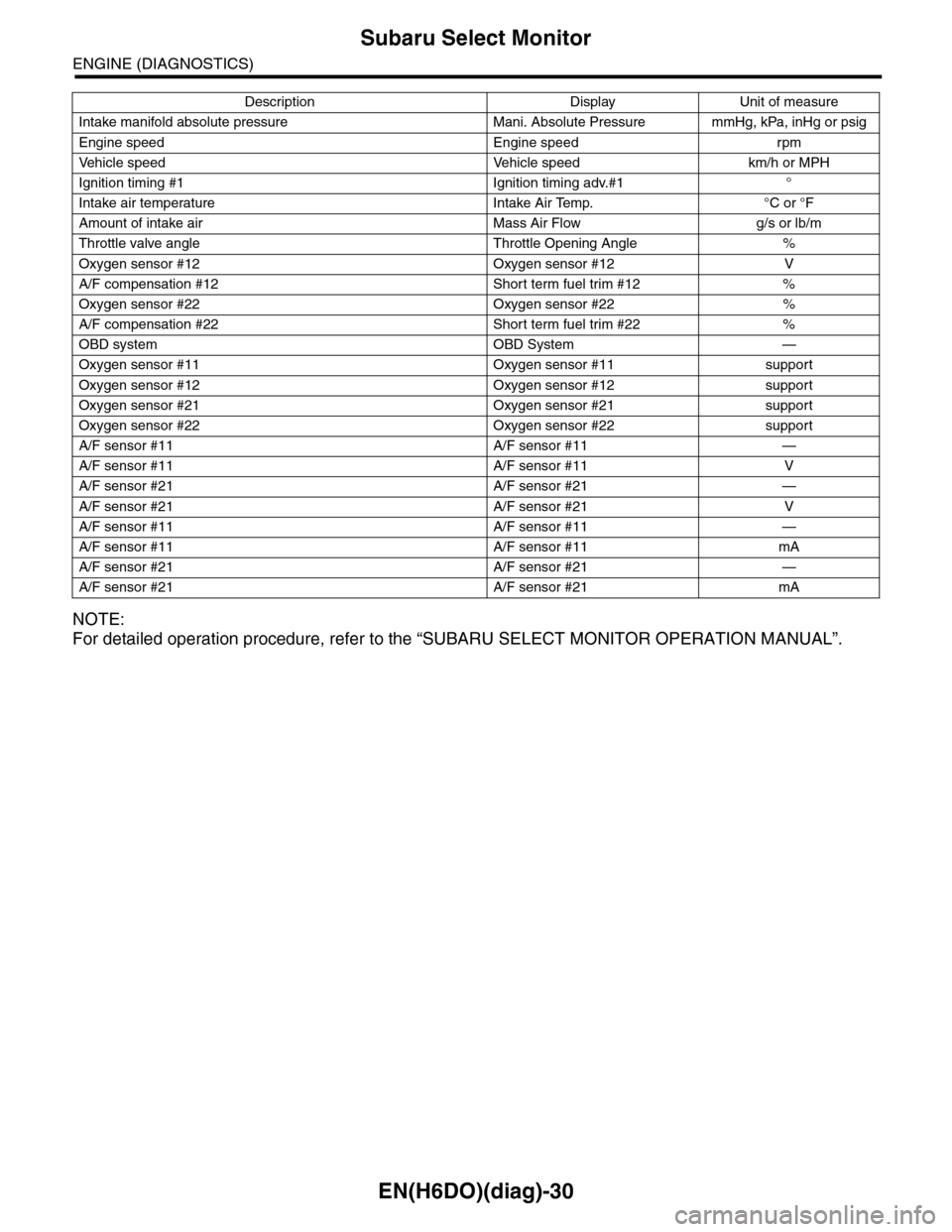
EN(H6DO)(diag)-30
Subaru Select Monitor
ENGINE (DIAGNOSTICS)
NOTE:
For detailed operation procedure, refer to the “SUBARU SELECT MONITOR OPERATION MANUAL”.
Intake manifold absolute pressure Mani. Absolute Pressure mmHg, kPa, inHg or psig
Engine speed Engine speed rpm
Ve h i c l e s p e e d Ve h i c l e s p e e d k m / h o r M P H
Ignition timing #1 Ignition timing adv.#1 °
Intake air temperature Intake Air Temp. °C or °F
Amount of intake air Mass Air Flow g/s or lb/m
Throttle valve angle Throttle Opening Angle %
Oxygen sensor #12 Oxygen sensor #12 V
A/F compensation #12 Short term fuel trim #12 %
Oxygen sensor #22 Oxygen sensor #22 %
A/F compensation #22 Short term fuel trim #22 %
OBD system OBD System —
Oxygen sensor #11 Oxygen sensor #11 support
Oxygen sensor #12 Oxygen sensor #12 support
Oxygen sensor #21 Oxygen sensor #21 support
Oxygen sensor #22 Oxygen sensor #22 support
A/F sensor #11 A/F sensor #11 —
A/F sensor #11 A/F sensor #11 V
A/F sensor #21 A/F sensor #21 —
A/F sensor #21 A/F sensor #21 V
A/F sensor #11 A/F sensor #11 —
A/F sensor #11 A/F sensor #11 mA
A/F sensor #21 A/F sensor #21 —
A/F sensor #21 A/F sensor #21 mA
Description Display Unit of measure
Page 1192 of 2453
![SUBARU TRIBECA 2009 1.G Service Workshop Manual EN(H6DO)(diag)-31
Subaru Select Monitor
ENGINE (DIAGNOSTICS)
6. READ FREEZE FRAME DATA FOR ENGINE (OBD MODE)
1) On the «Main Menu» display screen, select the {Each System Check} and press the [YES] SUBARU TRIBECA 2009 1.G Service Workshop Manual EN(H6DO)(diag)-31
Subaru Select Monitor
ENGINE (DIAGNOSTICS)
6. READ FREEZE FRAME DATA FOR ENGINE (OBD MODE)
1) On the «Main Menu» display screen, select the {Each System Check} and press the [YES]](/img/17/7322/w960_7322-1191.png)
EN(H6DO)(diag)-31
Subaru Select Monitor
ENGINE (DIAGNOSTICS)
6. READ FREEZE FRAME DATA FOR ENGINE (OBD MODE)
1) On the «Main Menu» display screen, select the {Each System Check} and press the [YES] key.
2) On the «System Selection Menu» display screen, select the {Engine} and press the [YES] key.
3) Press the [YES] key after the information of engine type has been displayed.
4) On the «Engine Diagnosis» display screen, select the {OBD System} and press the [YES] key.
5) On the «OBD Menu» display screen, select the {Freeze Frame Data} and press the [YES] key.
•A list of the support data is shown in the following table.
NOTE:
For detailed operation procedure, refer to the “SUBARU SELECT MONITOR OPERATION MANUAL”.
Description Display Unit of measure
DTC of freeze frame data Freeze frame data DTC
Air fuel ratio control system for bank 1 Fuel system for Bank1 —
Air fuel ratio control system for bank 2 Fuel system for Bank2 —
Engine load data Engine Load %
Engine coolant temperature signal Coolant Temp. °C or °F
Short term fuel trim by front oxygen (A/F) sensor (Bank 1) Short term fuel trim B1 %
Long term fuel trim by front oxygen (A/F) sensor (Bank 1) Long term fuel trim B1 %
Short term fuel trim by front oxygen (A/F) sensor (Bank 2) Short term fuel trim B2 %
Long term fuel trim by front oxygen (A/F) sensor (Bank 2) Long term fuel trim B2 %
Intake manifold absolute pressure signal Mani. Absolute Pressure mmHg, kPa, inHg or psig
Engine speed signal Engine Speed rpm
Ve h i c l e s p e e d s i g n a l Ve h i c l e S p e e d k m / h o r M P H
Ignition timing #1 Ignition timing adv. #1 °
Intake air temperature Intake Air Temp. °C
Amount of intake air Mass Air Flow g/s
Throttle valve angle Throttle Opening Angle %
Oxygen sensor #12 Oxygen sensor #12 V
A/F compensation #12 Short term fuel trim #12 %
Oxygen sensor #22 Oxygen sensor #22 V
A/F compensation #12 Short term fuel trim #22 %
Oxygen sensor #11 Oxygen sensor #11 support
Oxygen sensor #12 Oxygen sensor #12 support
Oxygen sensor #21 Oxygen sensor #21 support
Oxygen sensor #22 Oxygen sensor #22 support
Page 1193 of 2453
![SUBARU TRIBECA 2009 1.G Service Workshop Manual EN(H6DO)(diag)-32
Subaru Select Monitor
ENGINE (DIAGNOSTICS)
7. LED OPERATION MODE FOR ENGINE
1) On the «Main Menu» display screen, select the {Each System Check} and press the [YES] key.
2) On the SUBARU TRIBECA 2009 1.G Service Workshop Manual EN(H6DO)(diag)-32
Subaru Select Monitor
ENGINE (DIAGNOSTICS)
7. LED OPERATION MODE FOR ENGINE
1) On the «Main Menu» display screen, select the {Each System Check} and press the [YES] key.
2) On the](/img/17/7322/w960_7322-1192.png)
EN(H6DO)(diag)-32
Subaru Select Monitor
ENGINE (DIAGNOSTICS)
7. LED OPERATION MODE FOR ENGINE
1) On the «Main Menu» display screen, select the {Each System Check} and press the [YES] key.
2) On the «System Selection Menu» display screen, select the {Engine} and press the [YES] key.
3) Press the [YES] key after the information of engine type has been displayed.
4) On the «Engine Diagnosis» display screen, select the {Current Data Display/Save}, and then press the
[YES] key.
5) On the «Data Display» screen, select the {Data LED Display} and press the [YES] key.
6) Using the scroll key, scroll the display screen up or down until the desired data is shown.
•A list of the support data is shown in the following table.
NOTE:
For detailed operation procedure, refer to the “SUBARU SELECT MONITOR OPERATION MANUAL”.
Description Display Message When LED “ON” required
Te s t m o d e s i g n a l Te s t m o d e t e r m i n a l D c h e c k / U c h e c k D c h e c k
Neutral position switch signal Neutral SW Neutral/Other than neutral Neutral
Idle switch signal Soft idle SW Idle/Other than idle In idle
Ignition switch signal Ignition SW ON Input/OFF Input ON input
Pow er s te e r in g sw it c h s ig n al Pow er s te e r in g S W ON I np u t/ O FF I np u t ON i np ut
Air conditioning switch signal A/C SW ON Input/OFF Input ON input
Starter switch signal Starter SW ON Input/OFF Input ON input
Fr o nt ox yg e n mo n it o r 1 Ft O 2 mo n it o r 1 Le a n/ Ri ch Ric h
Fr o nt ox yg e n mo n it o r 2 Ft O 2 mo n it o r 2 Le a n/ Ri ch Ric h
Knocking signal Knock signal Yes/No Yes
Crankshaft position sensor signal Crankshaft angle signal Yes/No Yes
Camshaft position sensor signal Camshaft angle signal Yes/No Yes
Rear defogger switch signal Rear defogger SW ON Input/OFF Input ON input
Blower fan switch signal Blower fan SW ON Input/OFF Input ON input
Light switch signal Light SW ON Input/OFF Input ON input
Wiper switch signal Wiper SW ON Input/OFF Input ON input
A/C middle pressure switch signal A/C middle pressure SW ON Input/OFF Input ON input
Air conditioner compressor relay sig-
nalCompressor relay ON output/OFF output ON output
Drain valve signal Vent. Solenoid Valve ON or OFF When drain valve is ON.
AT r e t a r d a n g l e d e m a n d s i g n a l AT r e t a r d a n g l e d e m a n d Ye s / N o Ye s
AT f u e l c u t s i g n a l AT f u e l c u t Ye s / N o Ye s
VDC torque down prohibition output Torque down output ON/OFF Prohibition
VDC torque down demand Torque down demand Yes/No Yes
AT c o o r d i n a t e p e r m i s s i o n s i g n a lAT c o o r d i n a t e p e r m i s s i o n
signalON/OFF Permission
Electronic throttle control motor relay
signalETC motor relay ON/OFF ON
Stop light switch signal Stop SW ON Input/OFF Input ON input
SET/COAST switch signal SET/CST SW ON Input/OFF Input ON input
RESUME/ACCEL switch signal RES/ACC SW ON Input/OFF Input ON input
Brake switch signal Brake SW ON Input/OFF Input ON input
Main switch signal Main SW ON Input/OFF Input ON input
Body integrated unit data reception Body Int. Unit Data Yes/No Yes
Body integrated unit counter update Body Int. Unit Count Yes/No Yes
Cruise control cancel switch signal CC Cancel SW ON Input/OFF Input ON input
Va r i a b l e va l v e l i f t d i a g n o s i s o i l p r e s -
sure switch signal 1Oil Temperature SW1 ON/OFF ON
Va r i a b l e va l v e l i f t d i a g n o s i s o i l p r e s -
sure switch signal 2Oil Temperature SW2 ON/OFF ON
Page 1196 of 2453
EN(H6DO)(diag)-35
Inspection Mode
ENGINE (DIAGNOSTICS)
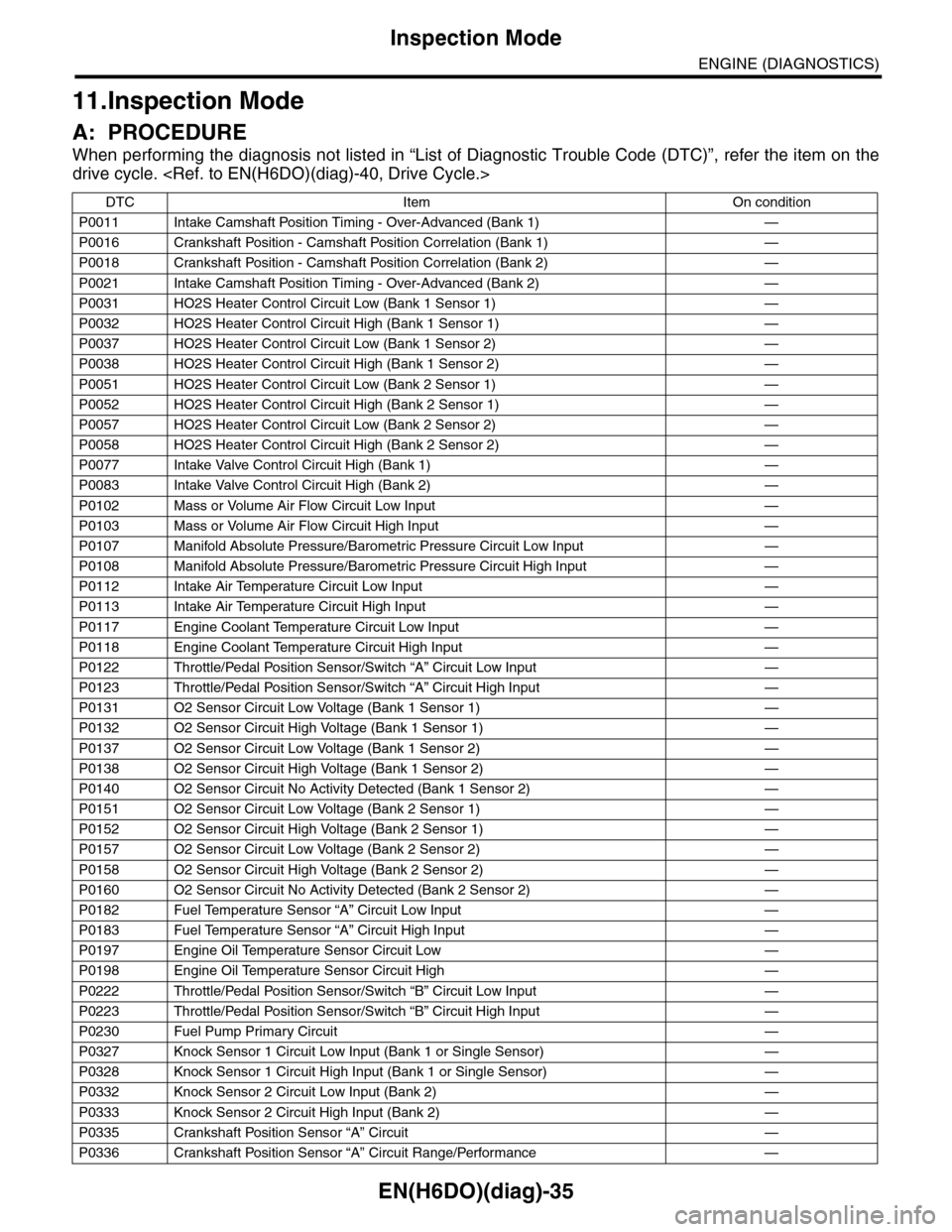
11.Inspection Mode
A: PROCEDURE
When performing the diagnosis not listed in “List of Diagnostic Trouble Code (DTC)”, refer the item on the
drive cycle.
DTC Item On condition
P0011 Intake Camshaft Position Timing - Over-Advanced (Bank 1) —
P0016 Crankshaft Position - Camshaft Position Correlation (Bank 1) —
P0018 Crankshaft Position - Camshaft Position Correlation (Bank 2) —
P0021 Intake Camshaft Position Timing - Over-Advanced (Bank 2) —
P0031 HO2S Heater Control Circuit Low (Bank 1 Sensor 1) —
P0032 HO2S Heater Control Circuit High (Bank 1 Sensor 1) —
P0037 HO2S Heater Control Circuit Low (Bank 1 Sensor 2) —
P0038 HO2S Heater Control Circuit High (Bank 1 Sensor 2) —
P0051 HO2S Heater Control Circuit Low (Bank 2 Sensor 1) —
P0052 HO2S Heater Control Circuit High (Bank 2 Sensor 1) —
P0057 HO2S Heater Control Circuit Low (Bank 2 Sensor 2) —
P0058 HO2S Heater Control Circuit High (Bank 2 Sensor 2) —
P0077 Intake Valve Control Circuit High (Bank 1) —
P0083 Intake Valve Control Circuit High (Bank 2) —
P0102 Mass or Volume Air Flow Circuit Low Input —
P0103 Mass or Volume Air Flow Circuit High Input —
P0107 Manifold Absolute Pressure/Barometric Pressure Circuit Low Input —
P0108 Manifold Absolute Pressure/Barometric Pressure Circuit High Input —
P0112 Intake Air Temperature Circuit Low Input —
P0113 Intake Air Temperature Circuit High Input —
P0117 Engine Coolant Temperature Circuit Low Input —
P0118 Engine Coolant Temperature Circuit High Input —
P0122 Throttle/Pedal Position Sensor/Switch “A” Circuit Low Input —
P0123 Throttle/Pedal Position Sensor/Switch “A” Circuit High Input —
P0131 O2 Sensor Circuit Low Voltage (Bank 1 Sensor 1) —
P0132 O2 Sensor Circuit High Voltage (Bank 1 Sensor 1) —
P0137 O2 Sensor Circuit Low Voltage (Bank 1 Sensor 2) —
P0138 O2 Sensor Circuit High Voltage (Bank 1 Sensor 2) —
P0140 O2 Sensor Circuit No Activity Detected (Bank 1 Sensor 2) —
P0151 O2 Sensor Circuit Low Voltage (Bank 2 Sensor 1) —
P0152 O2 Sensor Circuit High Voltage (Bank 2 Sensor 1) —
P0157 O2 Sensor Circuit Low Voltage (Bank 2 Sensor 2) —
P0158 O2 Sensor Circuit High Voltage (Bank 2 Sensor 2) —
P0160 O2 Sensor Circuit No Activity Detected (Bank 2 Sensor 2) —
P0182 Fuel Temperature Sensor “A” Circuit Low Input —
P0183 Fuel Temperature Sensor “A” Circuit High Input —
P0197 Engine Oil Temperature Sensor Circuit Low —
P0198 Engine Oil Temperature Sensor Circuit High —
P0222 Throttle/Pedal Position Sensor/Switch “B” Circuit Low Input —
P0223 Throttle/Pedal Position Sensor/Switch “B” Circuit High Input —
P0230 Fuel Pump Primary Circuit —
P0327 Knock Sensor 1 Circuit Low Input (Bank 1 or Single Sensor) —
P0328 Knock Sensor 1 Circuit High Input (Bank 1 or Single Sensor) —
P0332 Knock Sensor 2 Circuit Low Input (Bank 2) —
P0333 Knock Sensor 2 Circuit High Input (Bank 2) —
P0335 Crankshaft Position Sensor “A” Circuit —
P0336 Crankshaft Position Sensor “A” Circuit Range/Performance —
Page 1197 of 2453
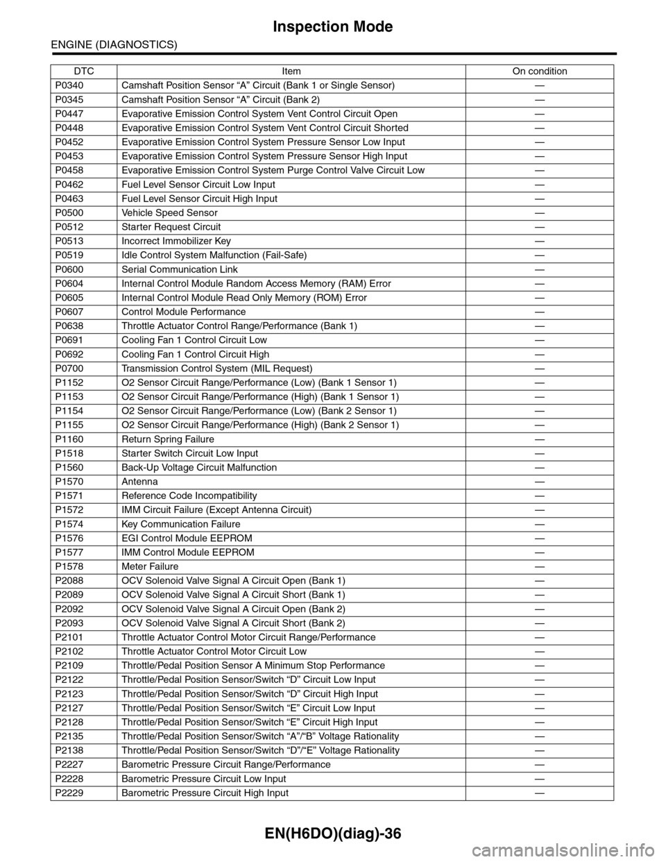
EN(H6DO)(diag)-36
Inspection Mode
ENGINE (DIAGNOSTICS)
P0340 Camshaft Position Sensor “A” Circuit (Bank 1 or Single Sensor) —
P0345 Camshaft Position Sensor “A” Circuit (Bank 2) —
P0447 Evaporative Emission Control System Vent Control Circuit Open —
P0448 Evaporative Emission Control System Vent Control Circuit Shorted —
P0452 Evaporative Emission Control System Pressure Sensor Low Input —
P0453 Evaporative Emission Control System Pressure Sensor High Input —
P0458 Evaporative Emission Control System Purge Control Valve Circuit Low —
P0462 Fuel Level Sensor Circuit Low Input —
P0463 Fuel Level Sensor Circuit High Input —
P0500 Vehicle Speed Sensor—
P0512 Starter Request Circuit—
P0513 Incorrect Immobilizer Key —
P0519 Idle Control System Malfunction (Fail-Safe) —
P0600 Serial Communication Link —
P0604 Internal Control Module Random Access Memory (RAM) Error —
P0605 Internal Control Module Read Only Memory (ROM) Error —
P0607 Control Module Performance —
P0638 Throttle Actuator Control Range/Performance (Bank 1) —
P0691 Cooling Fan 1 Control Circuit Low —
P0692 Cooling Fan 1 Control Circuit High —
P0700 Transmission Control System (MIL Request) —
P1152 O2 Sensor Circuit Range/Performance (Low) (Bank 1 Sensor 1) —
P1153 O2 Sensor Circuit Range/Performance (High) (Bank 1 Sensor 1) —
P1154 O2 Sensor Circuit Range/Performance (Low) (Bank 2 Sensor 1) —
P1155 O2 Sensor Circuit Range/Performance (High) (Bank 2 Sensor 1) —
P1160 Return Spring Failure—
P1518 Starter Switch Circuit Low Input —
P1560 Back-Up Voltage Circuit Malfunction —
P1570 Antenna—
P1571 Reference Code Incompatibility —
P1572 IMM Circuit Failure (Except Antenna Circuit) —
P1574 Key Communication Failure —
P1576 EGI Control Module EEPROM —
P1577 IMM Control Module EEPROM —
P1578 Meter Failure—
P2088 OCV Solenoid Valve Signal A Circuit Open (Bank 1) —
P2089 OCV Solenoid Valve Signal A Circuit Short (Bank 1) —
P2092 OCV Solenoid Valve Signal A Circuit Open (Bank 2) —
P2093 OCV Solenoid Valve Signal A Circuit Short (Bank 2) —
P2101 Throttle Actuator Control Motor Circuit Range/Performance —
P2102 Throttle Actuator Control Motor Circuit Low —
P2109 Throttle/Pedal Position Sensor A Minimum Stop Performance —
P2122 Throttle/Pedal Position Sensor/Switch “D” Circuit Low Input —
P2123 Throttle/Pedal Position Sensor/Switch “D” Circuit High Input —
P2127 Throttle/Pedal Position Sensor/Switch “E” Circuit Low Input —
P2128 Throttle/Pedal Position Sensor/Switch “E” Circuit High Input —
P2135 Throttle/Pedal Position Sensor/Switch “A”/“B” Voltage Rationality —
P2138 Throttle/Pedal Position Sensor/Switch “D”/“E” Voltage Rationality —
P2227 Barometric Pressure Circuit Range/Performance —
P2228 Barometric Pressure Circuit Low Input —
P2229 Barometric Pressure Circuit High Input —
DTC Item On condition