sensor SUBARU TRIBECA 2009 1.G Service Workshop Manual
[x] Cancel search | Manufacturer: SUBARU, Model Year: 2009, Model line: TRIBECA, Model: SUBARU TRIBECA 2009 1.GPages: 2453, PDF Size: 46.32 MB
Page 1104 of 2453
VDC-23
Rear ABS Wheel Speed Sensor
VEHICLE DYNAMICS CONTROL (VDC)
8. Rear ABS Wheel Speed Sen-
sor
A: REMOVAL
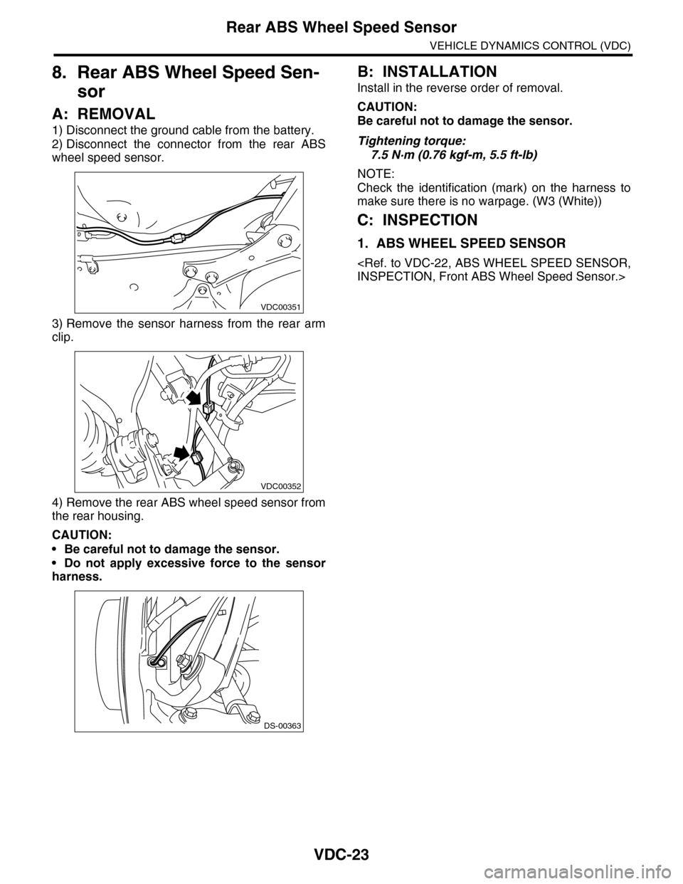
1) Disconnect the ground cable from the battery.
2) Disconnect the connector from the rear ABS
wheel speed sensor.
3) Remove the sensor harness from the rear arm
clip.
4) Remove the rear ABS wheel speed sensor from
the rear housing.
CAUTION:
•Be careful not to damage the sensor.
•Do not apply excessive force to the sensor
harness.
B: INSTALLATION
Install in the reverse order of removal.
CAUTION:
Be careful not to damage the sensor.
Tightening torque:
7.5 N·m (0.76 kgf-m, 5.5 ft-lb)
NOTE:
Check the identification (mark) on the harness to
make sure there is no warpage. (W3 (White))
C: INSPECTION
1. ABS WHEEL SPEED SENSOR
VDC00351
VDC00352
DS-00363
Page 1114 of 2453
WT-8
Wheel Balancing
WHEEL AND TIRE SYSTEM
4. Wheel Balancing
A: ADJUSTMENT
NOTE:
The balance weight for the outside of the wheel
uses an adhesive type weight. Change the setting
of the wheel balancer to an adhesive type weight.
1) Remove the balance weights.
CAUTION:
•Be careful not to damage the wheel.
•Completely remove the double–sided tape of
the adhesive type weight from the wheel.
2) Using the wheel balancer, measure wheel bal-
ance.
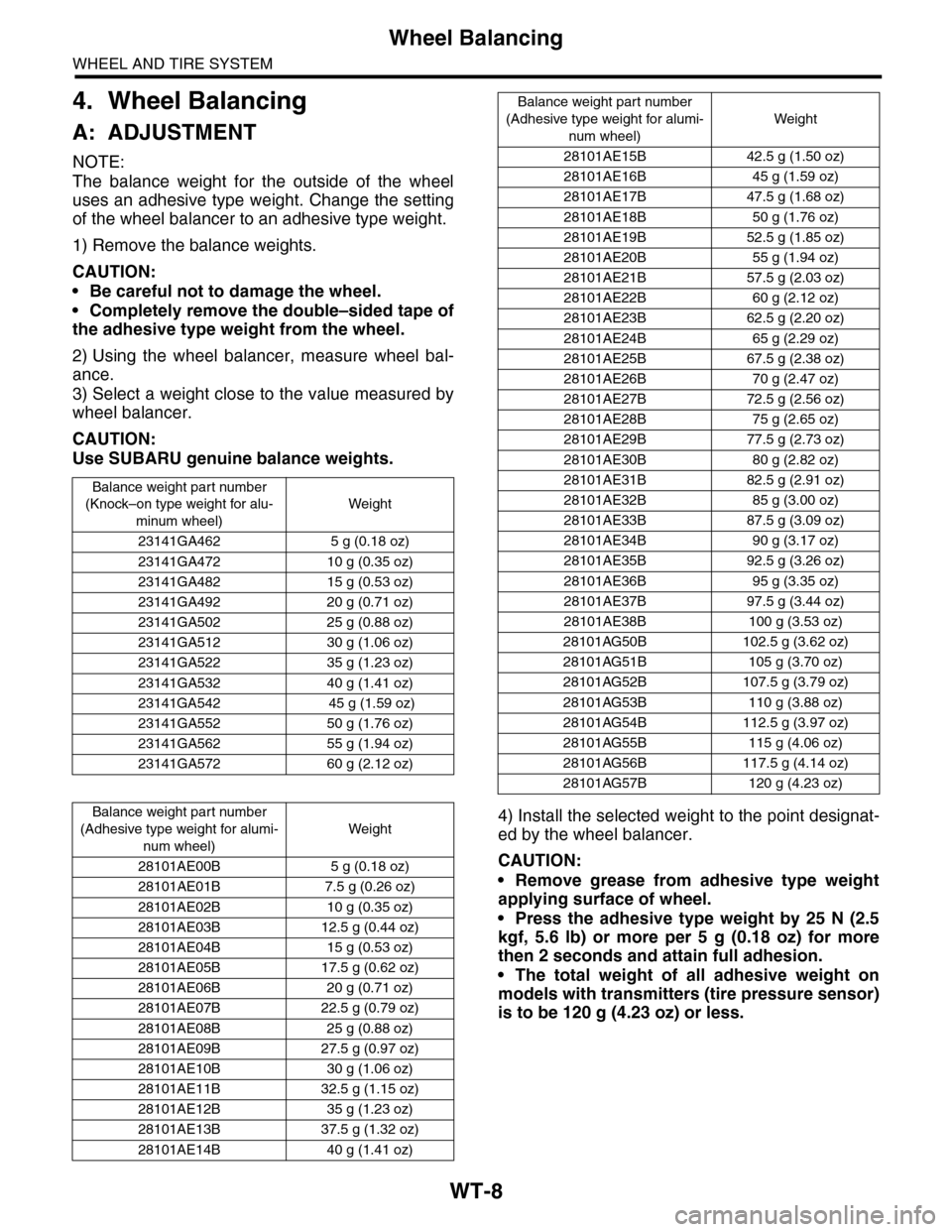
3) Select a weight close to the value measured by
wheel balancer.
CAUTION:
Use SUBARU genuine balance weights.
4) Install the selected weight to the point designat-
ed by the wheel balancer.
CAUTION:
•Remove grease from adhesive type weight
applying surface of wheel.
•Press the adhesive type weight by 25 N (2.5
kgf, 5.6 lb) or more per 5 g (0.18 oz) for more
then 2 seconds and attain full adhesion.
•The total weight of all adhesive weight on
models with transmitters (tire pressure sensor)
is to be 120 g (4.23 oz) or less.
Balance weight par t number
(Knock–on type weight for alu-
minum wheel)
Weight
23141GA462 5 g (0.18 oz)
23141GA472 10 g (0.35 oz)
23141GA482 15 g (0.53 oz)
23141GA492 20 g (0.71 oz)
23141GA502 25 g (0.88 oz)
23141GA512 30 g (1.06 oz)
23141GA522 35 g (1.23 oz)
23141GA532 40 g (1.41 oz)
23141GA542 45 g (1.59 oz)
23141GA552 50 g (1.76 oz)
23141GA562 55 g (1.94 oz)
23141GA572 60 g (2.12 oz)
Balance weight par t number
(Adhesive type weight for alumi-
num wheel)
Weight
28101AE00B 5 g (0.18 oz)
28101AE01B 7.5 g (0.26 oz)
28101AE02B 10 g (0.35 oz)
28101AE03B 12.5 g (0.44 oz)
28101AE04B 15 g (0.53 oz)
28101AE05B 17.5 g (0.62 oz)
28101AE06B 20 g (0.71 oz)
28101AE07B 22.5 g (0.79 oz)
28101AE08B 25 g (0.88 oz)
28101AE09B 27.5 g (0.97 oz)
28101AE10B 30 g (1.06 oz)
28101AE11B 32.5 g (1.15 oz)
28101AE12B 35 g (1.23 oz)
28101AE13B 37.5 g (1.32 oz)
28101AE14B 40 g (1.41 oz)
28101AE15B 42.5 g (1.50 oz)
28101AE16B 45 g (1.59 oz)
28101AE17B 47.5 g (1.68 oz)
28101AE18B 50 g (1.76 oz)
28101AE19B 52.5 g (1.85 oz)
28101AE20B 55 g (1.94 oz)
28101AE21B 57.5 g (2.03 oz)
28101AE22B 60 g (2.12 oz)
28101AE23B 62.5 g (2.20 oz)
28101AE24B 65 g (2.29 oz)
28101AE25B 67.5 g (2.38 oz)
28101AE26B 70 g (2.47 oz)
28101AE27B 72.5 g (2.56 oz)
28101AE28B 75 g (2.65 oz)
28101AE29B 77.5 g (2.73 oz)
28101AE30B 80 g (2.82 oz)
28101AE31B 82.5 g (2.91 oz)
28101AE32B 85 g (3.00 oz)
28101AE33B 87.5 g (3.09 oz)
28101AE34B 90 g (3.17 oz)
28101AE35B 92.5 g (3.26 oz)
28101AE36B 95 g (3.35 oz)
28101AE37B 97.5 g (3.44 oz)
28101AE38B 100 g (3.53 oz)
28101AG50B 102.5 g (3.62 oz)
28101AG51B 105 g (3.70 oz)
28101AG52B 107.5 g (3.79 oz)
28101AG53B 110 g (3.88 oz)
28101AG54B 112.5 g (3.97 oz)
28101AG55B 115 g (4.06 oz)
28101AG56B 117.5 g (4.14 oz)
28101AG57B 120 g (4.23 oz)
Balance weight part number
(Adhesive type weight for alumi-
num wheel)
Weight
Page 1125 of 2453
CO(H6DO)-6
General Description
COOLING
C: CAUTION
•Wear work clothing, including a cap, protective goggles and protective shoes during operation.
•Remove contamination including dirt and corrosion before removal, installation or disassembly.
•Keep the disassembled parts in order and protect them from dust and dirt.
•Before removal, installation or disassembly, be sure to clarify the failure. Avoid unnecessary removal, in-
stallation, disassembly and replacement.
•Be careful not to burn yourself, because each part on the vehicle is hot after running.
•Be sure to tighten fasteners including bolts and nuts to the specified torque.
•Place shop jacks or rigid racks at the specified points.
•Before disconnecting connectors of sensors or units, be sure to disconnect the ground cable from battery.
D: PREPARATION TOOL
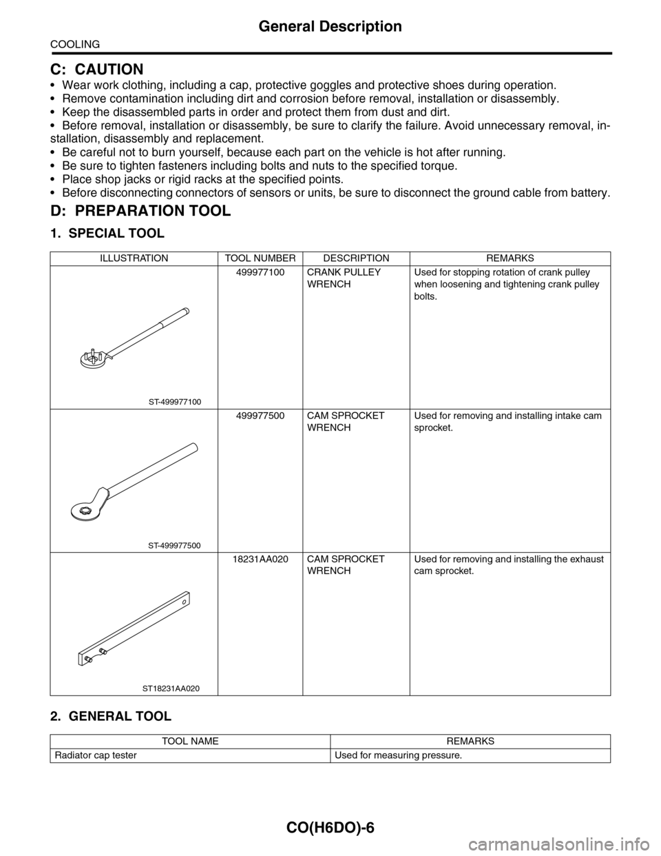
1. SPECIAL TOOL
2. GENERAL TOOL
ILLUSTRATION TOOL NUMBER DESCRIPTION REMARKS
499977100 CRANK PULLEY
WRENCH
Used for stopping rotation of crank pulley
when loosening and tightening crank pulley
bolts.
499977500 CAM SPROCKET
WRENCH
Used for removing and installing intake cam
sprocket.
18231AA020 CAM SPROCKET
WRENCH
Used for removing and installing the exhaust
cam sprocket.
TOOL NAME REMARKS
Radiator cap tester Used for measuring pressure.
ST-499977100
ST-499977500
ST18231AA020
Page 1135 of 2453
CO(H6DO)-16
Radiator
COOLING
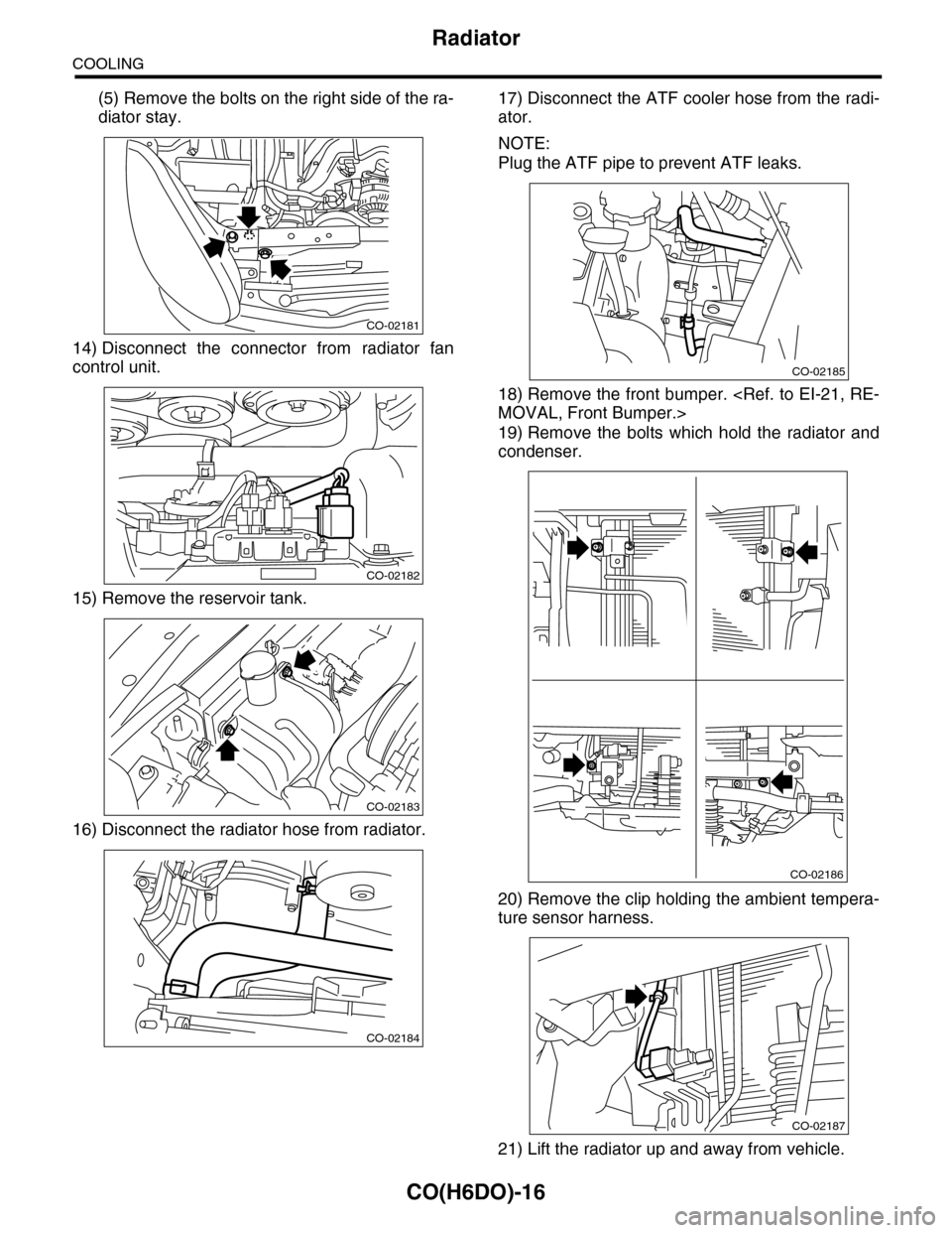
(5) Remove the bolts on the right side of the ra-
diator stay.
14) Disconnect the connector from radiator fan
control unit.
15) Remove the reservoir tank.
16) Disconnect the radiator hose from radiator.
17) Disconnect the ATF cooler hose from the radi-
ator.
NOTE:
Plug the ATF pipe to prevent ATF leaks.
18) Remove the front bumper.
19) Remove the bolts which hold the radiator and
condenser.
20) Remove the clip holding the ambient tempera-
ture sensor harness.
21) Lift the radiator up and away from vehicle.
CO-02181
CO-02182
CO-02183
CO-02184
CO-02185
CO-02186
CO-02187
Page 1136 of 2453
CO(H6DO)-17
Radiator
COOLING
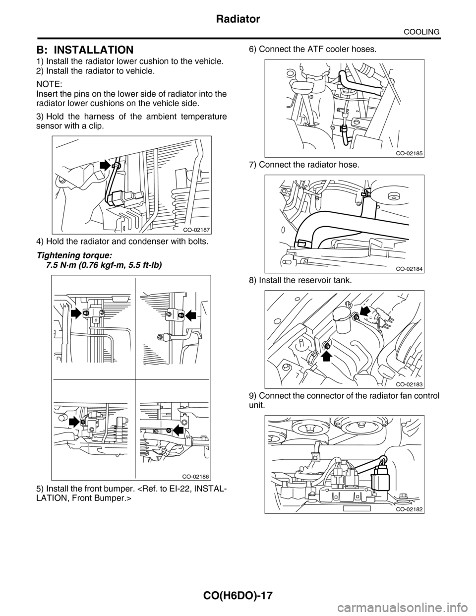
B: INSTALLATION
1) Install the radiator lower cushion to the vehicle.
2) Install the radiator to vehicle.
NOTE:
Insert the pins on the lower side of radiator into the
radiator lower cushions on the vehicle side.
3) Hold the harness of the ambient temperature
sensor with a clip.
4) Hold the radiator and condenser with bolts.
Tightening torque:
7.5 N·m (0.76 kgf-m, 5.5 ft-lb)
5) Install the front bumper.
6) Connect the ATF cooler hoses.
7) Connect the radiator hose.
8) Install the reservoir tank.
9) Connect the connector of the radiator fan control
unit.
CO-02187
CO-02186
CO-02185
CO-02184
CO-02183
CO-02182
Page 1149 of 2453
CO(H6DO)-30
Engine Cooling System Trouble in General
COOLING
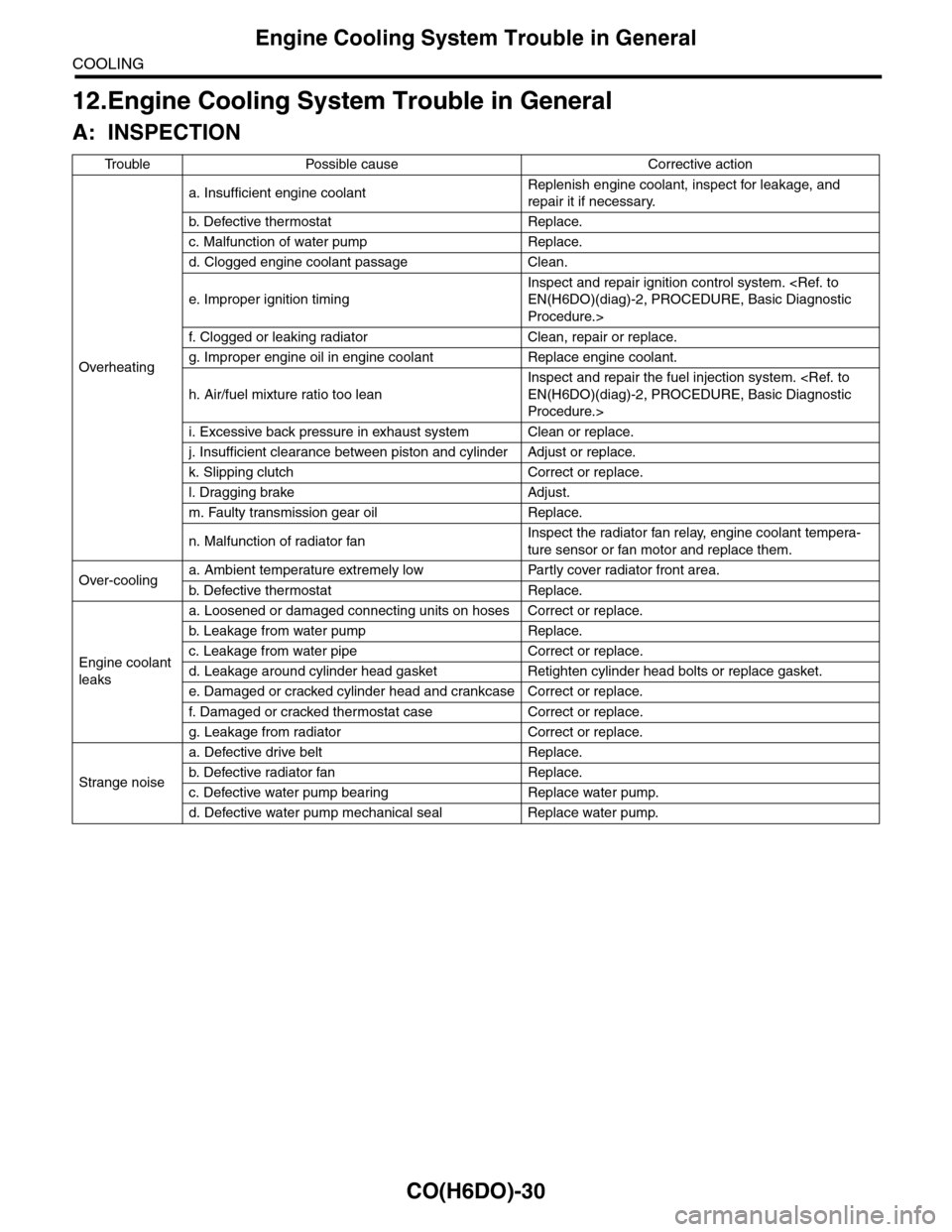
12.Engine Cooling System Trouble in General
A: INSPECTION
Tr o u b l e P o s s i b l e c a u s e C o r r e c t i v e a c t i o n
Overheating
a. Insufficient engine coolantReplenish engine coolant, inspect for leakage, and
repair it if necessary.
b. De fe c ti ve t he r mo st a t Rep la c e.
c. Malfunction of water pump Replace.
d. Clogged engine coolant passage Clean.
e. Improper ignition timing
Inspect and repair ignition control system.
Procedure.>
f. Clogged or leaking radiator Clean, repair or replace.
g. Improper engine oil in engine coolant Replace engine coolant.
h. Air/fuel mixture ratio too lean
Inspect and repair the fuel injection system.
Procedure.>
i. Excessive back pressure in exhaust system Clean or replace.
j. Insufficient clearance between piston and cylinder Adjust or replace.
k. Slipping clutch Correct or replace.
l. Dragging brake Adjust.
m. Faulty transmission gear oil Replace.
n. Malfunction of radiator fanInspect the radiator fan relay, engine coolant tempera-
ture sensor or fan motor and replace them.
Over-coolinga. Ambient temperature extremely low Partly cover radiator front area.
b. De fe c ti ve t he r mo st a t Rep la c e.
Engine coolant
leaks
a. Loosened or damaged connecting units on hoses Correct or replace.
b. L ea k ag e f r o m wat e r pu mp Rep la c e.
c. Leakage from water pipe Correct or replace.
d. Leakage around cylinder head gasket Retighten cylinder head bolts or replace gasket.
e. Damaged or cracked cylinder head and crankcase Correct or replace.
f. Damaged or cracked ther mostat case Correct or replace.
g. Leakage from radiator Correct or replace.
Strange noise
a. Defective drive belt Replace.
b. De fe c ti ve ra di a t or fan Rep la c e.
c. Defective water pump bearing Replace water pump.
d. Defective water pump mechanical seal Replace water pump.
Page 1150 of 2453
EC(H6DO)-2
General Description
EMISSION CONTROL (AUX. EMISSION CONTROL DEVICES)
1. General Description
A: CAUTION
•Wear work clothing, including a cap, protective
goggles and protective shoes during operation.
•Remove contamination including dirt and corro-
sion before removal, installation or disassembly.
•Keep the disassembled parts in order and pro-
tect them from dust and dirt.
•Before removal, installation or disassembly, be
sure to clarify the failure. Avoid unnecessary re-
moval, installation, disassembly and replacement.
•Be careful not to burn yourself, because each
part on the vehicle is hot after running.
•Be sure to tighten fasteners including bolts and
nuts to the specified torque.
•Place shop jacks or rigid racks at the specified
points.
•Before disconnecting connectors of sensors or
units, be sure to disconnect the ground cable from
the battery.
Page 1155 of 2453
EC(H6DO)-7
Fuel Level Sensor
EMISSION CONTROL (AUX. EMISSION CONTROL DEVICES)
6. Fuel Level Sensor
A: REMOVAL
For removal procedure, refer to “FU(H6DO)” sec-
tion.
B: INSTALLATION
For installation procedure, refer to “FU(H6DO)”
section.
Page 1156 of 2453
EC(H6DO)-8
Fuel Temperature Sensor
EMISSION CONTROL (AUX. EMISSION CONTROL DEVICES)
7. Fuel Temperature Sensor
A: REMOVAL
The fuel temperature sensor and fuel level sensor
are integrated into one unit; therefore, refer to “Fuel
Level Sensor” for removal procedure.
B: INSTALLATION
The fuel temperature sensor and fuel level sensor
are integrated into one unit; therefore, refer to “Fuel
Level Sensor” for installation procedure.
sor.>
Page 1157 of 2453
EC(H6DO)-9
Fuel Sub Level Sensor
EMISSION CONTROL (AUX. EMISSION CONTROL DEVICES)
8. Fuel Sub Level Sensor
A: REMOVAL
For removal procedure, refer to “FU(H6DO)” sec-
tion.
B: INSTALLATION
For installation procedure, refer to “FU(H6DO)”
section.