sensor SUBARU TRIBECA 2009 1.G Service Workshop Manual
[x] Cancel search | Manufacturer: SUBARU, Model Year: 2009, Model line: TRIBECA, Model: SUBARU TRIBECA 2009 1.GPages: 2453, PDF Size: 46.32 MB
Page 1060 of 2453
VDC(diag)-68
Diagnostic Procedure with Diagnostic Trouble Code (DTC)
VEHICLE DYNAMICS CONTROL (VDC) (DIAGNOSTICS)
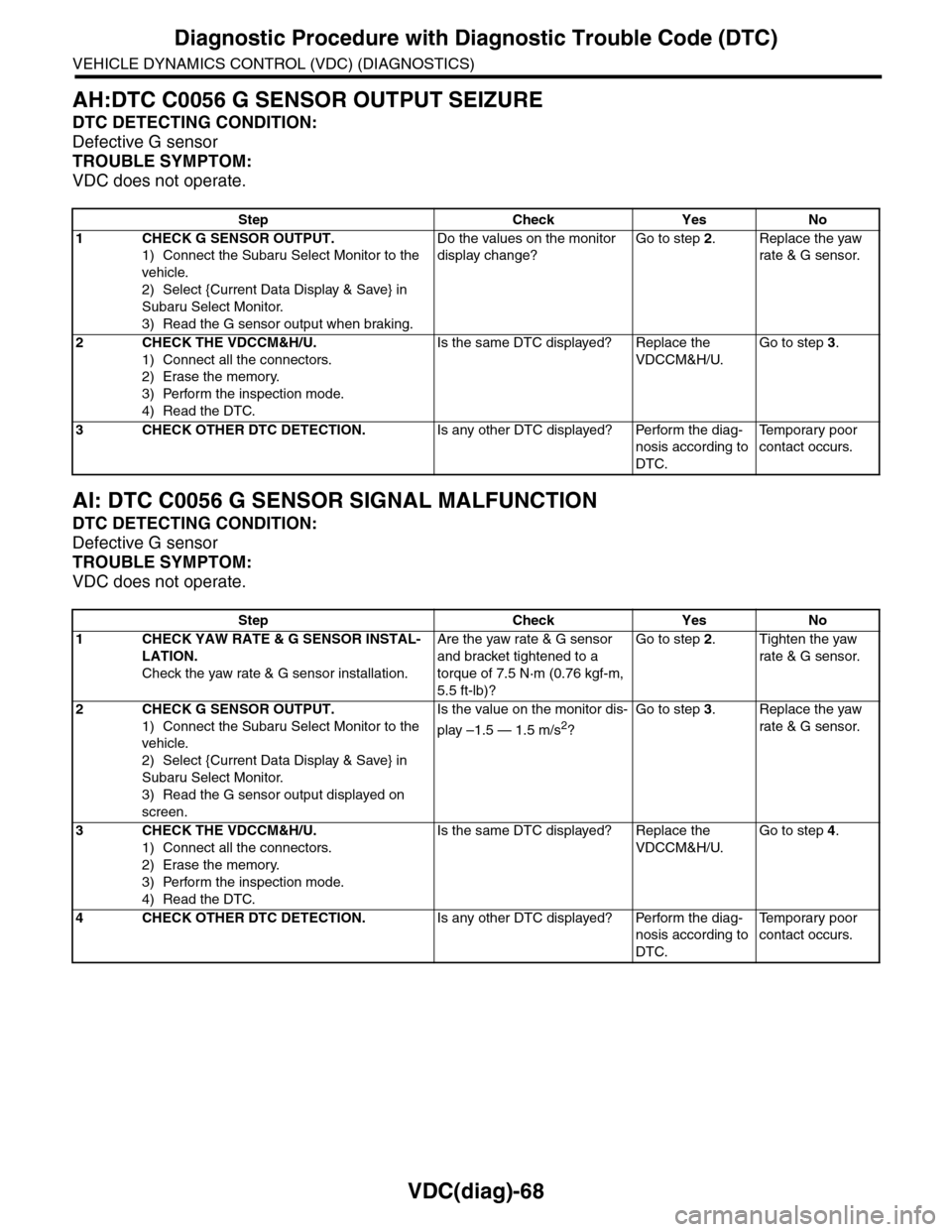
AH:DTC C0056 G SENSOR OUTPUT SEIZURE
DTC DETECTING CONDITION:
Defective G sensor
TROUBLE SYMPTOM:
VDC does not operate.
AI: DTC C0056 G SENSOR SIGNAL MALFUNCTION
DTC DETECTING CONDITION:
Defective G sensor
TROUBLE SYMPTOM:
VDC does not operate.
Step Check Yes No
1CHECK G SENSOR OUTPUT.
1) Connect the Subaru Select Monitor to the
vehicle.
2) Select {Current Data Display & Save} in
Subaru Select Monitor.
3) Read the G sensor output when braking.
Do the values on the monitor
display change?
Go to step 2.Replace the yaw
rate & G sensor.
2CHECK THE VDCCM&H/U.
1) Connect all the connectors.
2) Erase the memory.
3) Perform the inspection mode.
4) Read the DTC.
Is the same DTC displayed? Replace the
VDCCM&H/U.
Go to step 3.
3CHECK OTHER DTC DETECTION.Is any other DTC displayed? Perform the diag-
nosis according to
DTC.
Te m p o r a r y p o o r
contact occurs.
Step Check Yes No
1CHECK YAW RATE & G SENSOR INSTAL-
LATION.
Check the yaw rate & G sensor installation.
Are the yaw rate & G sensor
and bracket tightened to a
torque of 7.5 N·m (0.76 kgf-m,
5.5 ft-lb)?
Go to step 2.Tighten the yaw
rate & G sensor.
2CHECK G SENSOR OUTPUT.
1) Connect the Subaru Select Monitor to the
vehicle.
2) Select {Current Data Display & Save} in
Subaru Select Monitor.
3) Read the G sensor output displayed on
screen.
Is the value on the monitor dis-
play –1.5 — 1.5 m/s2?
Go to step 3.Replace the yaw
rate & G sensor.
3CHECK THE VDCCM&H/U.
1) Connect all the connectors.
2) Erase the memory.
3) Perform the inspection mode.
4) Read the DTC.
Is the same DTC displayed? Replace the
VDCCM&H/U.
Go to step 4.
4CHECK OTHER DTC DETECTION.Is any other DTC displayed? Perform the diag-
nosis according to
DTC.
Te m p o r a r y p o o r
contact occurs.
Page 1061 of 2453
VDC(diag)-69
Diagnostic Procedure with Diagnostic Trouble Code (DTC)
VEHICLE DYNAMICS CONTROL (VDC) (DIAGNOSTICS)
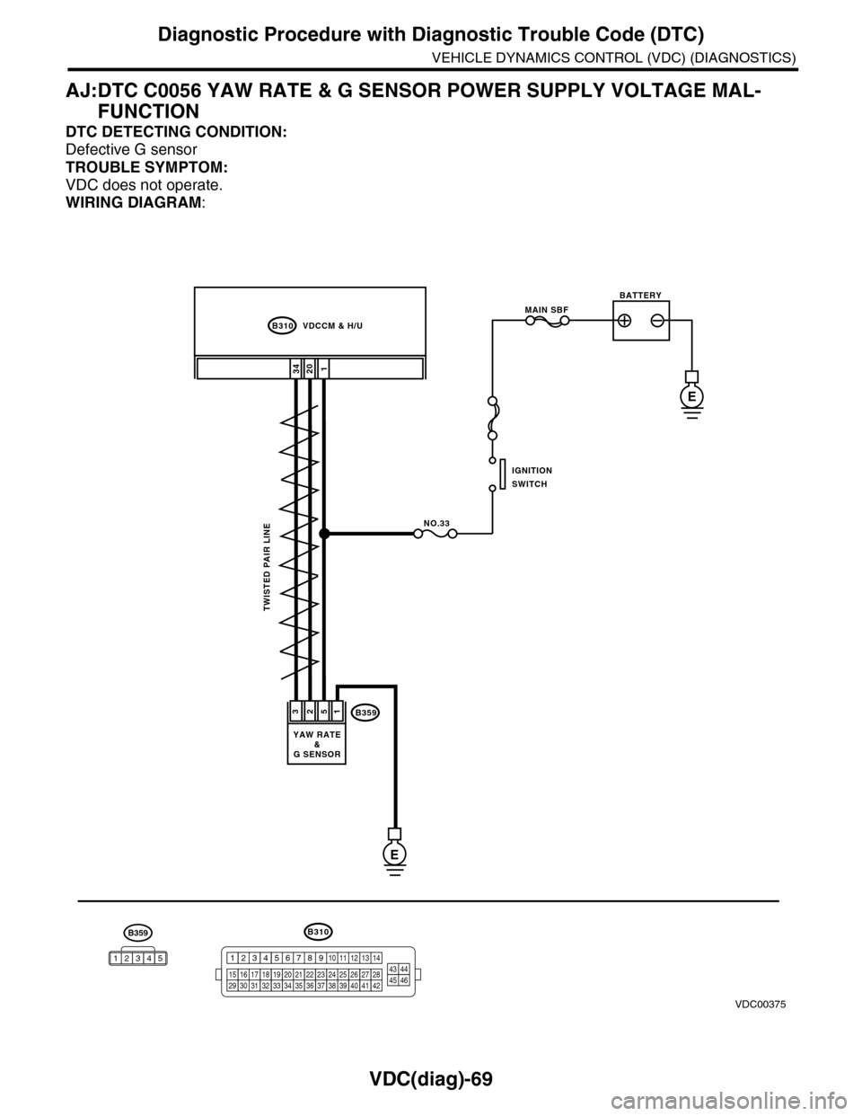
AJ:DTC C0056 YAW RATE & G SENSOR POWER SUPPLY VOLTAGE MAL-
FUNCTION
DTC DETECTING CONDITION:
Defective G sensor
TROUBLE SYMPTOM:
VDC does not operate.
WIRING DIAGRAM:
B310
12034
B359
E
3512
B310 VDCCM & H/U
TWISTED PAIR LINE
YAW RATE&G SENSOR
1234
1516171819202122232425262728293031323334353637383940414245464344568910 11 12 13 147
VDC00375
B359
12345
MAIN SBF
NO.33
E
BATTERY
IGNITIONSWITCH
Page 1062 of 2453
VDC(diag)-70
Diagnostic Procedure with Diagnostic Trouble Code (DTC)
VEHICLE DYNAMICS CONTROL (VDC) (DIAGNOSTICS)
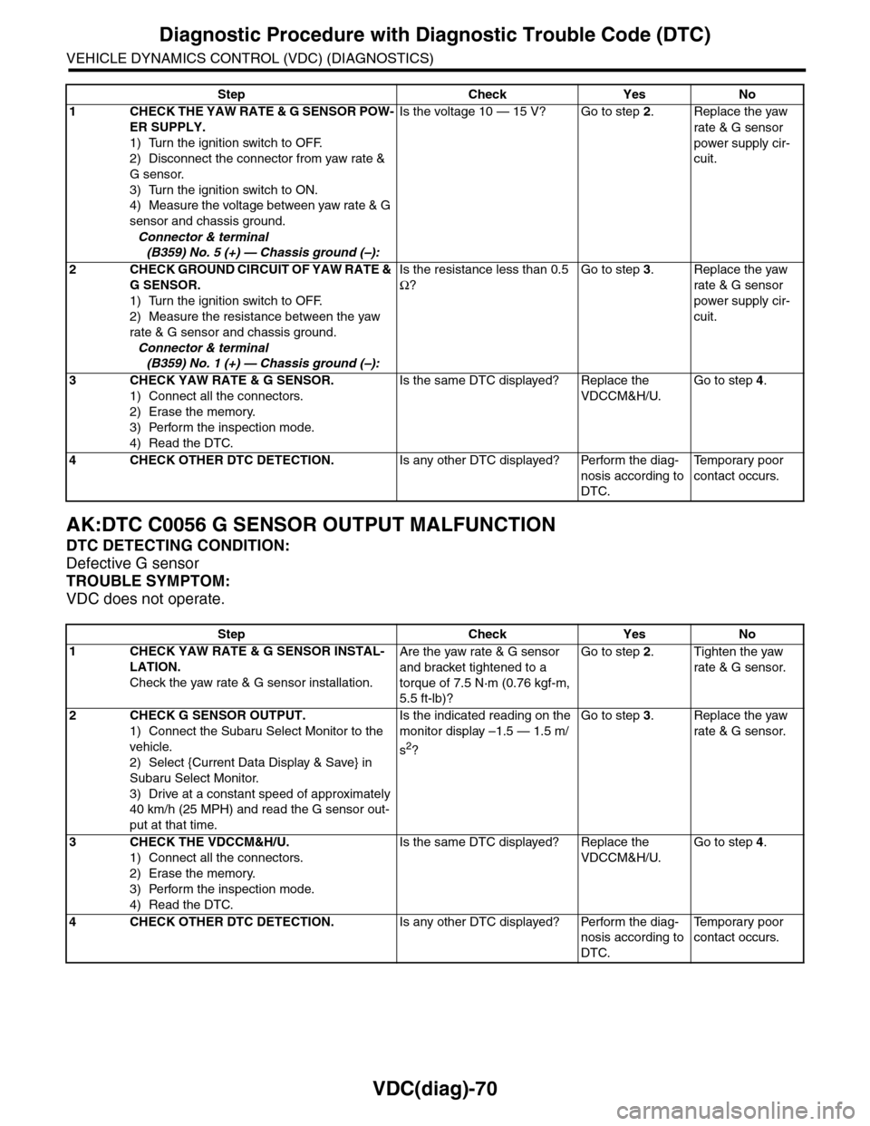
AK:DTC C0056 G SENSOR OUTPUT MALFUNCTION
DTC DETECTING CONDITION:
Defective G sensor
TROUBLE SYMPTOM:
VDC does not operate.
Step Check Yes No
1CHECK THE YAW RATE & G SENSOR POW-
ER SUPPLY.
1) Turn the ignition switch to OFF.
2) Disconnect the connector from yaw rate &
G sensor.
3) Turn the ignition switch to ON.
4) Measure the voltage between yaw rate & G
sensor and chassis ground.
Connector & terminal
(B359) No. 5 (+) — Chassis ground (–):
Is the voltage 10 — 15 V? Go to step 2.Replace the yaw
rate & G sensor
power supply cir-
cuit.
2CHECK GROUND CIRCUIT OF YAW RATE &
G SENSOR.
1) Turn the ignition switch to OFF.
2) Measure the resistance between the yaw
rate & G sensor and chassis ground.
Connector & terminal
(B359) No. 1 (+) — Chassis ground (–):
Is the resistance less than 0.5
Ω?
Go to step 3.Replace the yaw
rate & G sensor
power supply cir-
cuit.
3CHECK YAW RATE & G SENSOR.
1) Connect all the connectors.
2) Erase the memory.
3) Perform the inspection mode.
4) Read the DTC.
Is the same DTC displayed? Replace the
VDCCM&H/U.
Go to step 4.
4CHECK OTHER DTC DETECTION.Is any other DTC displayed? Perform the diag-
nosis according to
DTC.
Te m p o r a r y p o o r
contact occurs.
Step Check Yes No
1CHECK YAW RATE & G SENSOR INSTAL-
LATION.
Check the yaw rate & G sensor installation.
Are the yaw rate & G sensor
and bracket tightened to a
torque of 7.5 N·m (0.76 kgf-m,
5.5 ft-lb)?
Go to step 2.Tighten the yaw
rate & G sensor.
2CHECK G SENSOR OUTPUT.
1) Connect the Subaru Select Monitor to the
vehicle.
2) Select {Current Data Display & Save} in
Subaru Select Monitor.
3) Drive at a constant speed of approximately
40 km/h (25 MPH) and read the G sensor out-
put at that time.
Is the indicated reading on the
monitor display –1.5 — 1.5 m/
s2?
Go to step 3.Replace the yaw
rate & G sensor.
3CHECK THE VDCCM&H/U.
1) Connect all the connectors.
2) Erase the memory.
3) Perform the inspection mode.
4) Read the DTC.
Is the same DTC displayed? Replace the
VDCCM&H/U.
Go to step 4.
4CHECK OTHER DTC DETECTION.Is any other DTC displayed? Perform the diag-
nosis according to
DTC.
Te m p o r a r y p o o r
contact occurs.
Page 1065 of 2453
VDC(diag)-73
Diagnostic Procedure with Diagnostic Trouble Code (DTC)
VEHICLE DYNAMICS CONTROL (VDC) (DIAGNOSTICS)
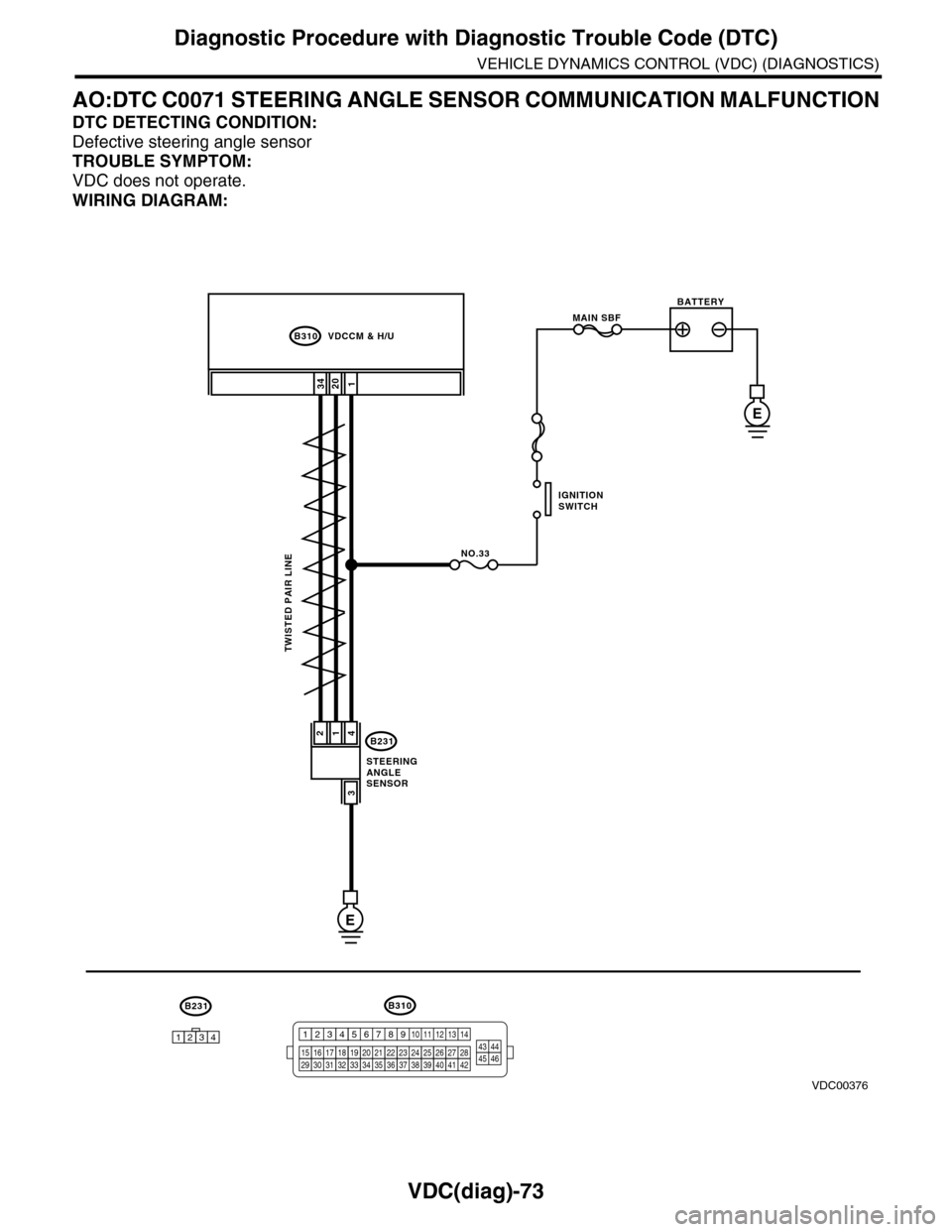
AO:DTC C0071 STEERING ANGLE SENSOR COMMUNICATION MALFUNCTION
DTC DETECTING CONDITION:
Defective steering angle sensor
TROUBLE SYMPTOM:
VDC does not operate.
WIRING DIAGRAM:
B310
1234
B231
12034
B231
E
241
3
B310 VDCCM & H/U
TWISTED PAIR LINE
STEERINGANGLESENSOR
1234
1516171819202122232425262728293031323334353637383940414245464344568910 11 12 13 147
VDC00376
MAIN SBF
NO.33
E
BATTERY
IGNITIONSWITCH
Page 1066 of 2453
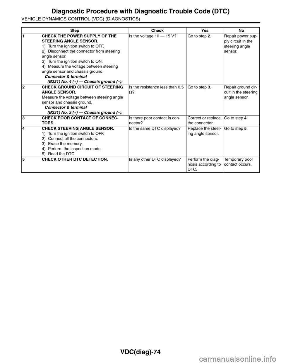
VDC(diag)-74
Diagnostic Procedure with Diagnostic Trouble Code (DTC)
VEHICLE DYNAMICS CONTROL (VDC) (DIAGNOSTICS)
Step Check Yes No
1CHECK THE POWER SUPPLY OF THE
STEERING ANGLE SENSOR.
1) Turn the ignition switch to OFF.
2) Disconnect the connector from steering
angle sensor.
3) Turn the ignition switch to ON.
4) Measure the voltage between steering
angle sensor and chassis ground.
Connector & terminal
(B231) No. 4 (+) — Chassis ground (–):
Is the voltage 10 — 15 V? Go to step 2.Repair power sup-
ply circuit in the
steering angle
sensor.
2CHECK GROUND CIRCUIT OF STEERING
ANGLE SENSOR.
Measure the voltage between steering angle
sensor and chassis ground.
Connector & terminal
(B231) No. 3 (+) — Chassis ground (–):
Is the resistance less than 0.5
Ω?
Go to step 3.Repair ground cir-
cuit in the steering
angle sensor.
3CHECK POOR CONTACT OF CONNEC-
TORS.
Is there poor contact in con-
nector?
Correct or replace
the connector.
Go to step 4.
4CHECK STEERING ANGLE SENSOR.
1) Turn the ignition switch to OFF.
2) Connect all the connectors.
3) Erase the memory.
4) Perform the inspection mode.
5) Read the DTC.
Is the same DTC displayed? Replace the steer-
ing angle sensor.
Go to step 5.
5CHECK OTHER DTC DETECTION.Is any other DTC displayed? Perform the diag-
nosis according to
DTC.
Te m p o r a r y p o o r
contact occurs.
Page 1067 of 2453
VDC(diag)-75
Diagnostic Procedure with Diagnostic Trouble Code (DTC)
VEHICLE DYNAMICS CONTROL (VDC) (DIAGNOSTICS)
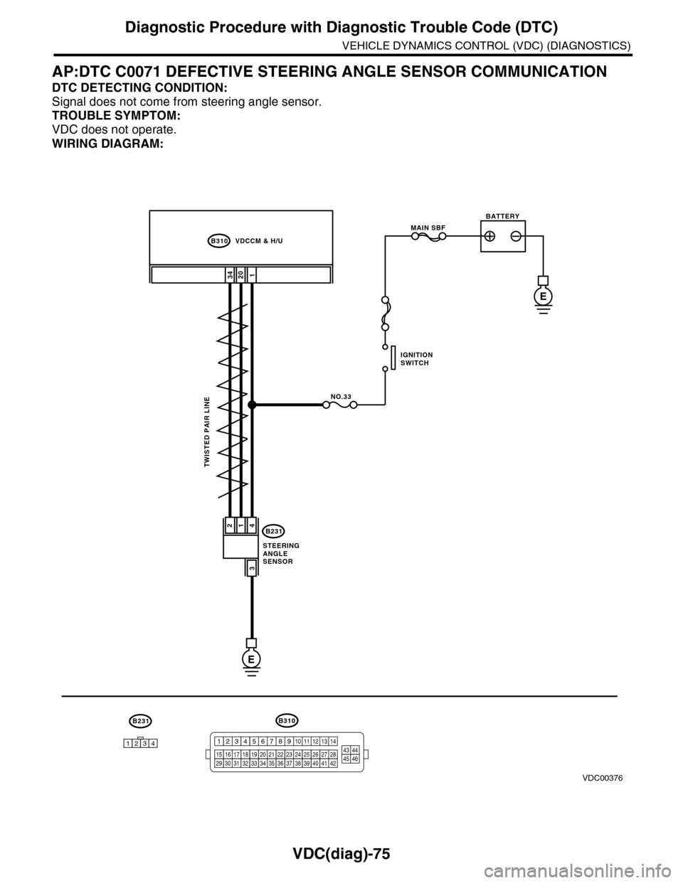
AP:DTC C0071 DEFECTIVE STEERING ANGLE SENSOR COMMUNICATION
DTC DETECTING CONDITION:
Signal does not come from steering angle sensor.
TROUBLE SYMPTOM:
VDC does not operate.
WIRING DIAGRAM:
B310
1234
B231
12034
B231
E
241
3
B310 VDCCM & H/U
TWISTED PAIR LINE
STEERINGANGLESENSOR
1234
1516171819202122232425262728293031323334353637383940414245464344568910 11 12 13 147
VDC00376
MAIN SBF
NO.33
E
BATTERY
IGNITIONSWITCH
Page 1068 of 2453
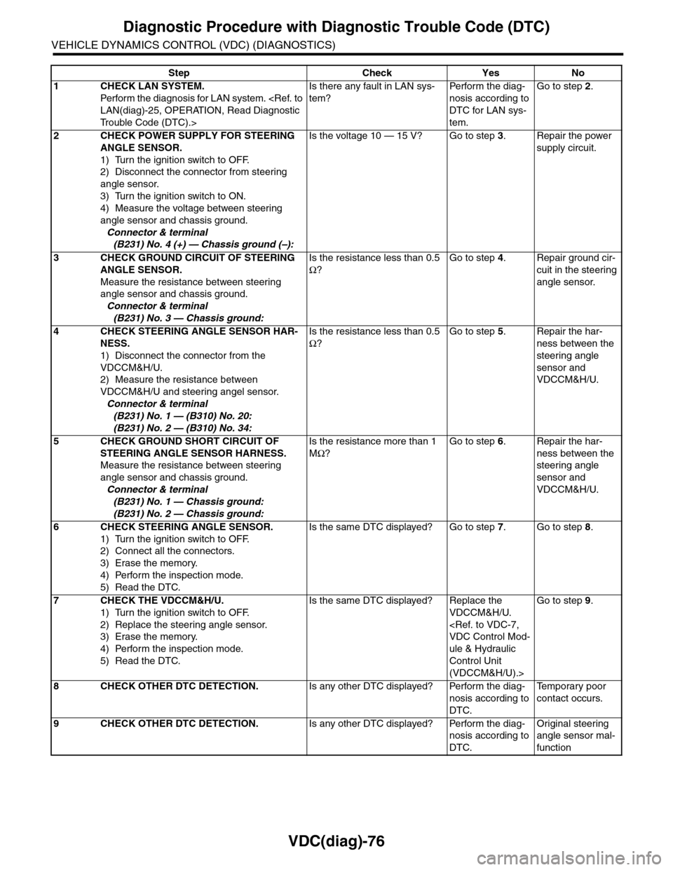
VDC(diag)-76
Diagnostic Procedure with Diagnostic Trouble Code (DTC)
VEHICLE DYNAMICS CONTROL (VDC) (DIAGNOSTICS)
Step Check Yes No
1CHECK LAN SYSTEM.
Perfor m the diagnosis for LAN system.
Tr o u b l e C o d e ( D T C ) . >
Is there any fault in LAN sys-
tem?
Pe r for m t h e d ia g -
nosis according to
DTC for LAN sys-
tem.
Go to step 2.
2CHECK POWER SUPPLY FOR STEERING
ANGLE SENSOR.
1) Turn the ignition switch to OFF.
2) Disconnect the connector from steering
angle sensor.
3) Turn the ignition switch to ON.
4) Measure the voltage between steering
angle sensor and chassis ground.
Connector & terminal
(B231) No. 4 (+) — Chassis ground (–):
Is the voltage 10 — 15 V? Go to step 3.Repair the power
supply circuit.
3CHECK GROUND CIRCUIT OF STEERING
ANGLE SENSOR.
Measure the resistance between steering
angle sensor and chassis ground.
Connector & terminal
(B231) No. 3 — Chassis ground:
Is the resistance less than 0.5
Ω?
Go to step 4.Repair ground cir-
cuit in the steering
angle sensor.
4CHECK STEERING ANGLE SENSOR HAR-
NESS.
1) Disconnect the connector from the
VDCCM&H/U.
2) Measure the resistance between
VDCCM&H/U and steering angel sensor.
Connector & terminal
(B231) No. 1 — (B310) No. 20:
(B231) No. 2 — (B310) No. 34:
Is the resistance less than 0.5
Ω?
Go to step 5.Repair the har-
ness between the
steering angle
sensor and
VDCCM&H/U.
5CHECK GROUND SHORT CIRCUIT OF
STEERING ANGLE SENSOR HARNESS.
Measure the resistance between steering
angle sensor and chassis ground.
Connector & terminal
(B231) No. 1 — Chassis ground:
(B231) No. 2 — Chassis ground:
Is the resistance more than 1
MΩ?
Go to step 6.Repair the har-
ness between the
steering angle
sensor and
VDCCM&H/U.
6CHECK STEERING ANGLE SENSOR.
1) Turn the ignition switch to OFF.
2) Connect all the connectors.
3) Erase the memory.
4) Perform the inspection mode.
5) Read the DTC.
Is the same DTC displayed? Go to step 7.Go to step 8.
7CHECK THE VDCCM&H/U.
1) Turn the ignition switch to OFF.
2) Replace the steering angle sensor.
3) Erase the memory.
4) Perform the inspection mode.
5) Read the DTC.
Is the same DTC displayed? Replace the
VDCCM&H/U.
ule & Hydraulic
Control Unit
(VDCCM&H/U).>
Go to step 9.
8CHECK OTHER DTC DETECTION.Is any other DTC displayed? Perform the diag-
nosis according to
DTC.
Te m p o r a r y p o o r
contact occurs.
9CHECK OTHER DTC DETECTION.Is any other DTC displayed? Perform the diag-
nosis according to
DTC.
Original steering
angle sensor mal-
function
Page 1069 of 2453
VDC(diag)-77
Diagnostic Procedure with Diagnostic Trouble Code (DTC)
VEHICLE DYNAMICS CONTROL (VDC) (DIAGNOSTICS)
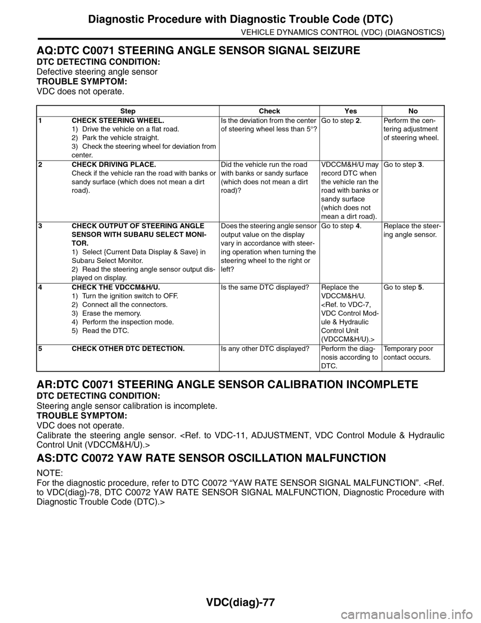
AQ:DTC C0071 STEERING ANGLE SENSOR SIGNAL SEIZURE
DTC DETECTING CONDITION:
Defective steering angle sensor
TROUBLE SYMPTOM:
VDC does not operate.
AR:DTC C0071 STEERING ANGLE SENSOR CALIBRATION INCOMPLETE
DTC DETECTING CONDITION:
Steering angle sensor calibration is incomplete.
TROUBLE SYMPTOM:
VDC does not operate.
Calibrate the steering angle sensor.
AS:DTC C0072 YAW RATE SENSOR OSCILLATION MALFUNCTION
NOTE:
For the diagnostic procedure, refer to DTC C0072 “YAW RATE SENSOR SIGNAL MALFUNCTION”.
Diagnostic Trouble Code (DTC).>
Step Check Yes No
1CHECK STEERING WHEEL.
1) Drive the vehicle on a flat road.
2) Park the vehicle straight.
3) Check the steering wheel for deviation from
center.
Is the deviation from the center
of steering wheel less than 5°?
Go to step 2.Perform the cen-
tering adjustment
of steering wheel.
2CHECK DRIVING PLACE.
Check if the vehicle ran the road with banks or
sandy surface (which does not mean a dirt
road).
Did the vehicle run the road
with banks or sandy surface
(which does not mean a dirt
road)?
VDCCM&H/U may
record DTC when
the vehicle ran the
road with banks or
sandy surface
(which does not
mean a dirt road).
Go to step 3.
3CHECK OUTPUT OF STEERING ANGLE
SENSOR WITH SUBARU SELECT MONI-
TOR.
1) Select {Current Data Display & Save} in
Subaru Select Monitor.
2) Read the steering angle sensor output dis-
played on display.
Does the steering angle sensor
output value on the display
var y in accordance with steer-
ing operation when turning the
steering wheel to the right or
left?
Go to step 4.Replace the steer-
ing angle sensor.
4CHECK THE VDCCM&H/U.
1) Turn the ignition switch to OFF.
2) Connect all the connectors.
3) Erase the memory.
4) Perform the inspection mode.
5) Read the DTC.
Is the same DTC displayed? Replace the
VDCCM&H/U.
ule & Hydraulic
Control Unit
(VDCCM&H/U).>
Go to step 5.
5CHECK OTHER DTC DETECTION.Is any other DTC displayed? Perform the diag-
nosis according to
DTC.
Te m p o r a r y p o o r
contact occurs.
Page 1070 of 2453
VDC(diag)-78
Diagnostic Procedure with Diagnostic Trouble Code (DTC)
VEHICLE DYNAMICS CONTROL (VDC) (DIAGNOSTICS)
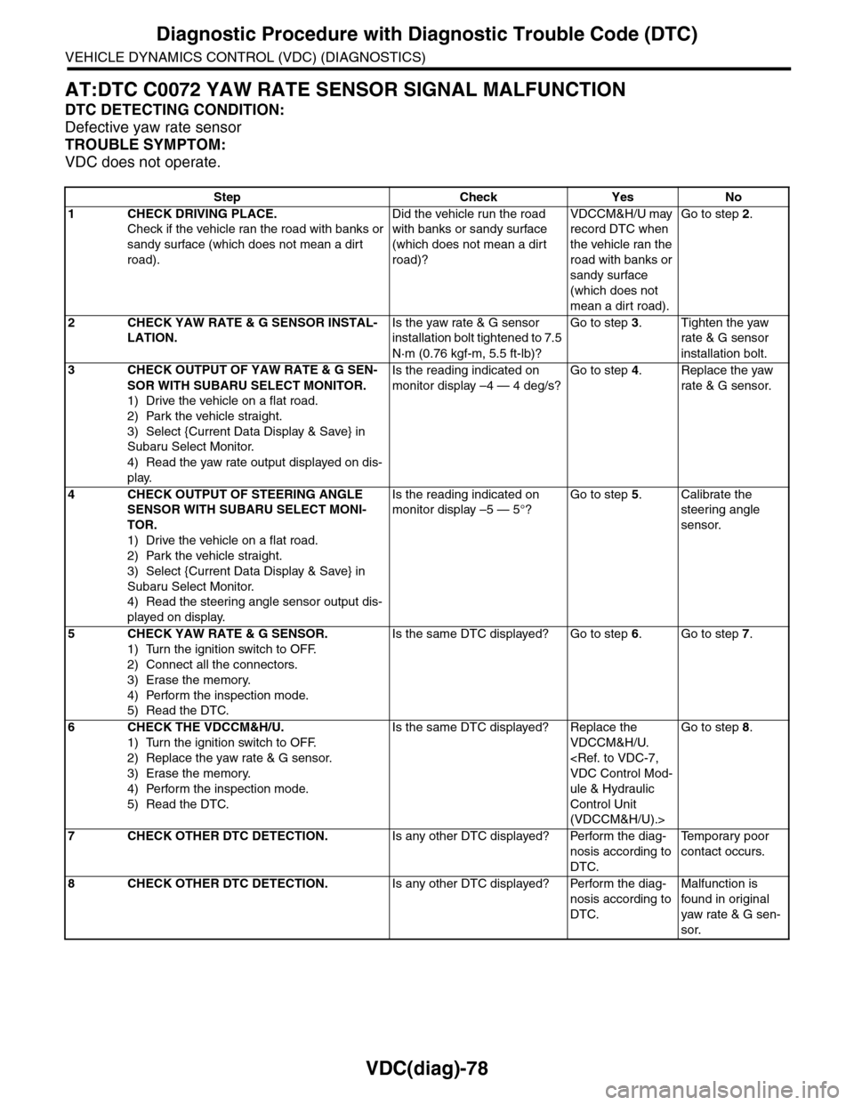
AT:DTC C0072 YAW RATE SENSOR SIGNAL MALFUNCTION
DTC DETECTING CONDITION:
Defective yaw rate sensor
TROUBLE SYMPTOM:
VDC does not operate.
Step Check Yes No
1CHECK DRIVING PLACE.
Check if the vehicle ran the road with banks or
sandy surface (which does not mean a dirt
road).
Did the vehicle run the road
with banks or sandy surface
(which does not mean a dirt
road)?
VDCCM&H/U may
record DTC when
the vehicle ran the
road with banks or
sandy surface
(which does not
mean a dirt road).
Go to step 2.
2CHECK YAW RATE & G SENSOR INSTAL-
LATION.
Is the yaw rate & G sensor
installation bolt tightened to 7.5
N·m (0.76 kgf-m, 5.5 ft-lb)?
Go to step 3.Tighten the yaw
rate & G sensor
installation bolt.
3CHECK OUTPUT OF YAW RATE & G SEN-
SOR WITH SUBARU SELECT MONITOR.
1) Drive the vehicle on a flat road.
2) Park the vehicle straight.
3) Select {Current Data Display & Save} in
Subaru Select Monitor.
4) Read the yaw rate output displayed on dis-
play.
Is the reading indicated on
monitor display –4 — 4 deg/s?
Go to step 4.Replace the yaw
rate & G sensor.
4CHECK OUTPUT OF STEERING ANGLE
SENSOR WITH SUBARU SELECT MONI-
TOR.
1) Drive the vehicle on a flat road.
2) Park the vehicle straight.
3) Select {Current Data Display & Save} in
Subaru Select Monitor.
4) Read the steering angle sensor output dis-
played on display.
Is the reading indicated on
monitor display –5 — 5°?
Go to step 5.Calibrate the
steering angle
sensor.
5CHECK YAW RATE & G SENSOR.
1) Turn the ignition switch to OFF.
2) Connect all the connectors.
3) Erase the memory.
4) Perform the inspection mode.
5) Read the DTC.
Is the same DTC displayed? Go to step 6.Go to step 7.
6CHECK THE VDCCM&H/U.
1) Turn the ignition switch to OFF.
2) Replace the yaw rate & G sensor.
3) Erase the memory.
4) Perform the inspection mode.
5) Read the DTC.
Is the same DTC displayed? Replace the
VDCCM&H/U.
ule & Hydraulic
Control Unit
(VDCCM&H/U).>
Go to step 8.
7CHECK OTHER DTC DETECTION.Is any other DTC displayed? Perform the diag-
nosis according to
DTC.
Te m p o r a r y p o o r
contact occurs.
8CHECK OTHER DTC DETECTION.Is any other DTC displayed? Perform the diag-
nosis according to
DTC.
Malfunction is
found in or iginal
yaw rate & G sen-
sor.
Page 1071 of 2453
VDC(diag)-79
Diagnostic Procedure with Diagnostic Trouble Code (DTC)
VEHICLE DYNAMICS CONTROL (VDC) (DIAGNOSTICS)
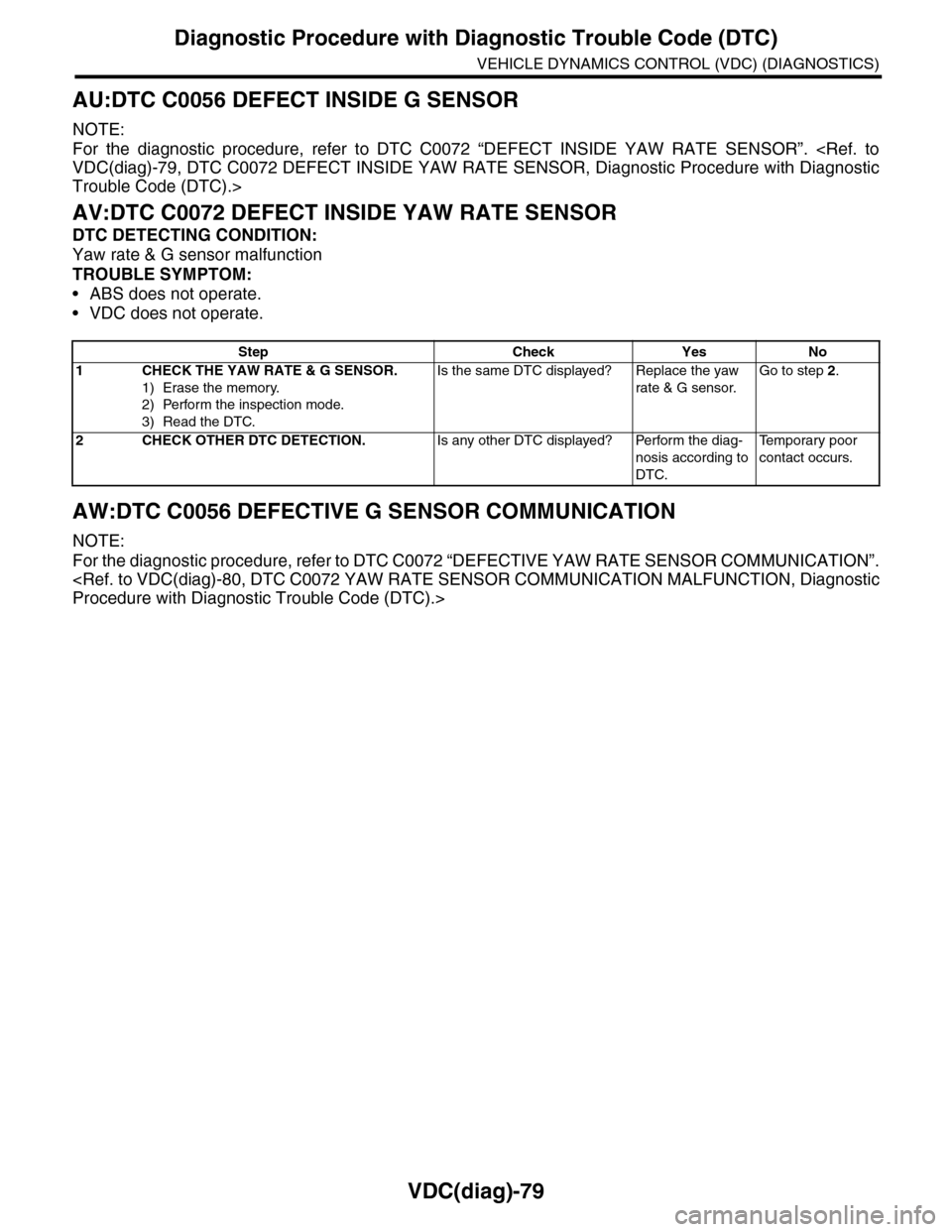
AU:DTC C0056 DEFECT INSIDE G SENSOR
NOTE:
For the diagnostic procedure, refer to DTC C0072 “DEFECT INSIDE YAW RATE SENSOR”.
Trouble Code (DTC).>
AV:DTC C0072 DEFECT INSIDE YAW RATE SENSOR
DTC DETECTING CONDITION:
Yaw rate & G sensor malfunction
TROUBLE SYMPTOM:
•ABS does not operate.
•VDC does not operate.
AW:DTC C0056 DEFECTIVE G SENSOR COMMUNICATION
NOTE:
For the diagnostic procedure, refer to DTC C0072 “DEFECTIVE YAW RATE SENSOR COMMUNICATION”.
Step Check Yes No
1CHECK THE YAW RATE & G SENSOR.
1) Erase the memory.
2) Perform the inspection mode.
3) Read the DTC.
Is the same DTC displayed? Replace the yaw
rate & G sensor.
Go to step 2.
2CHECK OTHER DTC DETECTION.Is any other DTC displayed? Perform the diag-
nosis according to
DTC.
Te m p o r a r y p o o r
contact occurs.