sensor SUBARU TRIBECA 2009 1.G Service Workshop Manual
[x] Cancel search | Manufacturer: SUBARU, Model Year: 2009, Model line: TRIBECA, Model: SUBARU TRIBECA 2009 1.GPages: 2453, PDF Size: 46.32 MB
Page 1234 of 2453
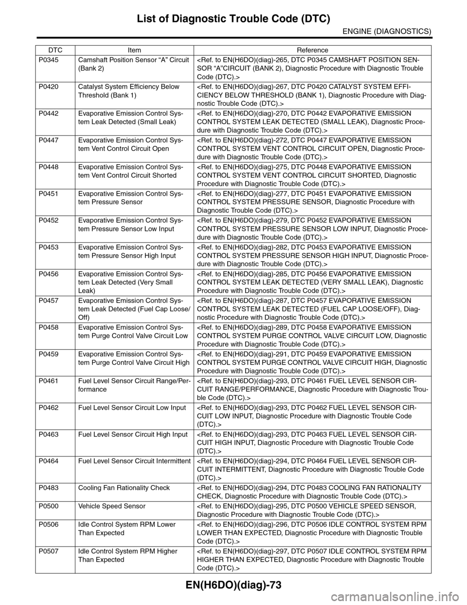
EN(H6DO)(diag)-73
List of Diagnostic Trouble Code (DTC)
ENGINE (DIAGNOSTICS)
P0345 Camshaft Position Sensor “A” Circuit
(Bank 2)
Code (DTC).>
P0420 Catalyst System Efficiency Below
Threshold (Bank 1)
nostic Trouble Code (DTC).>
P0442 Evaporative Emission Control Sys-
tem Leak Detected (Small Leak)
dure with Diagnostic Trouble Code (DTC).>
P0447 Evaporative Emission Control Sys-
tem Vent Control Circuit Open
dure with Diagnostic Trouble Code (DTC).>
P0448 Evaporative Emission Control Sys-
tem Vent Control Circuit Shorted
Procedure with Diagnostic Trouble Code (DTC).>
P0451 Evaporative Emission Control Sys-
tem Pressure Sensor
Diagnostic Trouble Code (DTC).>
P0452 Evaporative Emission Control Sys-
tem Pressure Sensor Low Input
dure with Diagnostic Trouble Code (DTC).>
P0453 Evaporative Emission Control Sys-
tem Pressure Sensor High Input
dure with Diagnostic Trouble Code (DTC).>
P0456 Evaporative Emission Control Sys-
tem Leak Detected (Very Small
Leak)
Procedure with Diagnostic Trouble Code (DTC).>
P0457 Evaporative Emission Control Sys-
tem Leak Detected (Fuel Cap Loose/
Off)
nostic Procedure with Diagnostic Trouble Code (DTC).>
P0458 Evaporative Emission Control Sys-
tem Purge Control Valve Circuit Low
Procedure with Diagnostic Trouble Code (DTC).>
P0459 Evaporative Emission Control Sys-
tem Purge Control Valve Circuit High
Procedure with Diagnostic Trouble Code (DTC).>
P0461 Fuel Level Sensor Circuit Range/Per-
for mance
ble Code (DTC).>
P0462 Fuel Level Sensor Circuit Low Input
(DTC).>
P0463 Fuel Level Sensor Circuit High Input
(DTC).>
P0464 Fuel Level Sensor Circuit Intermittent
(DTC).>
P0483 Cooling Fan Rationality Check
P0500 Vehicle Speed Sensor
P0506 Idle Control System RPM Lower
Than Expected
Code (DTC).>
P0507 Idle Control System RPM Higher
Than Expected
Code (DTC).>
DTC Item Reference
Page 1235 of 2453
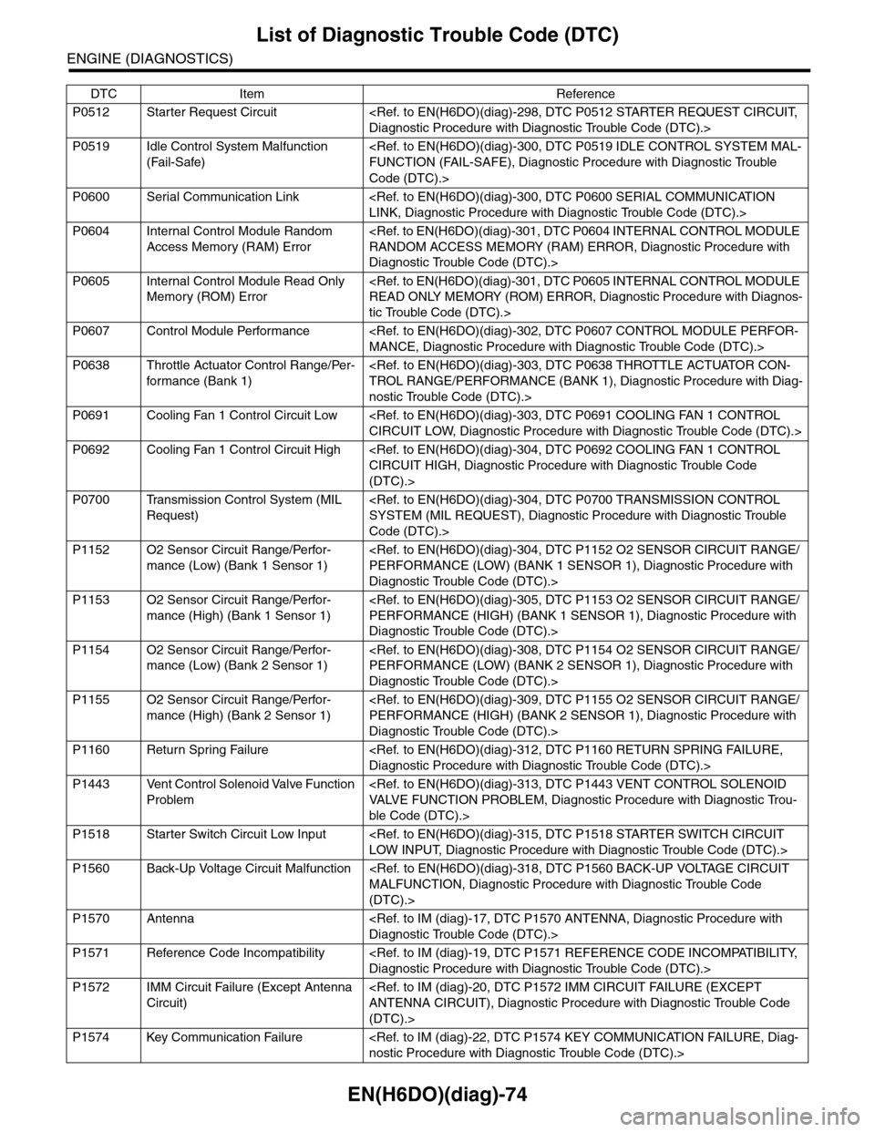
EN(H6DO)(diag)-74
List of Diagnostic Trouble Code (DTC)
ENGINE (DIAGNOSTICS)
P0512 Starter Request Circuit
P0519 Idle Control System Malfunction
(Fail-Safe)
Code (DTC).>
P0600 Serial Communication Link
P0604 Internal Control Module Random
Access Memory (RAM) Error
Diagnostic Trouble Code (DTC).>
P0605 Internal Control Module Read Only
Memory (ROM) Error
tic Trouble Code (DTC).>
P0607 Control Module Performance
P0638 Throttle Actuator Control Range/Per-
for mance (Bank 1)
nostic Trouble Code (DTC).>
P0691 Cooling Fan 1 Control Circuit Low
P0692 Cooling Fan 1 Control Circuit High
(DTC).>
P0700 Transmission Control System (MIL
Request)
Code (DTC).>
P1152 O2 Sensor Circuit Range/Perfor-
mance (Low) (Bank 1 Sensor 1)
Diagnostic Trouble Code (DTC).>
P1153 O2 Sensor Circuit Range/Perfor-
mance (High) (Bank 1 Sensor 1)
Diagnostic Trouble Code (DTC).>
P1154 O2 Sensor Circuit Range/Perfor-
mance (Low) (Bank 2 Sensor 1)
Diagnostic Trouble Code (DTC).>
P1155 O2 Sensor Circuit Range/Perfor-
mance (High) (Bank 2 Sensor 1)
Diagnostic Trouble Code (DTC).>
P1160 Return Spring Failure
P1443 Vent Control Solenoid Valve Function
Problem
ble Code (DTC).>
P1518 Starter Switch Circuit Low Input
P1560 Back-Up Voltage Circuit Malfunction
(DTC).>
P1570 Antenna
P1571 Reference Code Incompatibility
P1572 IMM Circuit Failure (Except Antenna
Circuit)
(DTC).>
P1574 Key Communication Failure
DTC Item Reference
Page 1236 of 2453
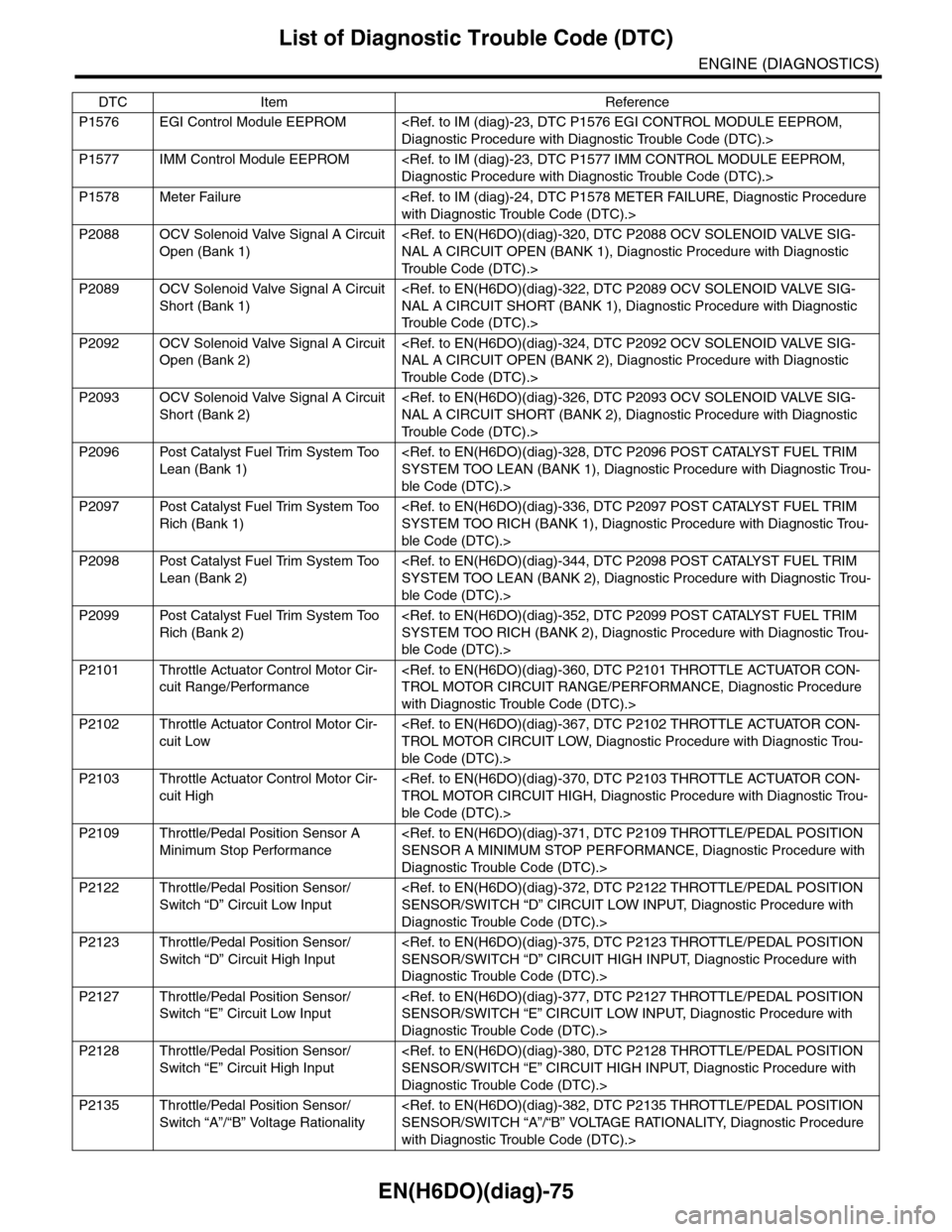
EN(H6DO)(diag)-75
List of Diagnostic Trouble Code (DTC)
ENGINE (DIAGNOSTICS)
P1576 EGI Control Module EEPROM
P1577 IMM Control Module EEPROM
P1578 Meter Failure
P2088 OCV Solenoid Valve Signal A Circuit
Open (Bank 1)
Tr o u b l e C o d e ( D T C ) . >
P2089 OCV Solenoid Valve Signal A Circuit
Short (Bank 1)
Tr o u b l e C o d e ( D T C ) . >
P2092 OCV Solenoid Valve Signal A Circuit
Open (Bank 2)
Tr o u b l e C o d e ( D T C ) . >
P2093 OCV Solenoid Valve Signal A Circuit
Short (Bank 2)
Tr o u b l e C o d e ( D T C ) . >
P2096 Post Catalyst Fuel Trim System Too
Lean (Bank 1)
ble Code (DTC).>
P2097 Post Catalyst Fuel Trim System Too
Rich (Bank 1)
ble Code (DTC).>
P2098 Post Catalyst Fuel Trim System Too
Lean (Bank 2)
ble Code (DTC).>
P2099 Post Catalyst Fuel Trim System Too
Rich (Bank 2)
ble Code (DTC).>
P2101 Throttle Actuator Control Motor Cir-
cuit Range/Performance
with Diagnostic Trouble Code (DTC).>
P2102 Throttle Actuator Control Motor Cir-
cuit Low
ble Code (DTC).>
P2103 Throttle Actuator Control Motor Cir-
cuit High
ble Code (DTC).>
P2109 Throttle/Pedal Position Sensor A
Minimum Stop Performance
Diagnostic Trouble Code (DTC).>
P2122 Throttle/Pedal Position Sensor/
Switch “D” Circuit Low Input
Diagnostic Trouble Code (DTC).>
P2123 Throttle/Pedal Position Sensor/
Switch “D” Circuit High Input
Diagnostic Trouble Code (DTC).>
P2127 Throttle/Pedal Position Sensor/
Switch “E” Circuit Low Input
Diagnostic Trouble Code (DTC).>
P2128 Throttle/Pedal Position Sensor/
Switch “E” Circuit High Input
Diagnostic Trouble Code (DTC).>
P2135 Throttle/Pedal Position Sensor/
Switch “A”/“B” Voltage Rationality
with Diagnostic Trouble Code (DTC).>
DTC Item Reference
Page 1237 of 2453
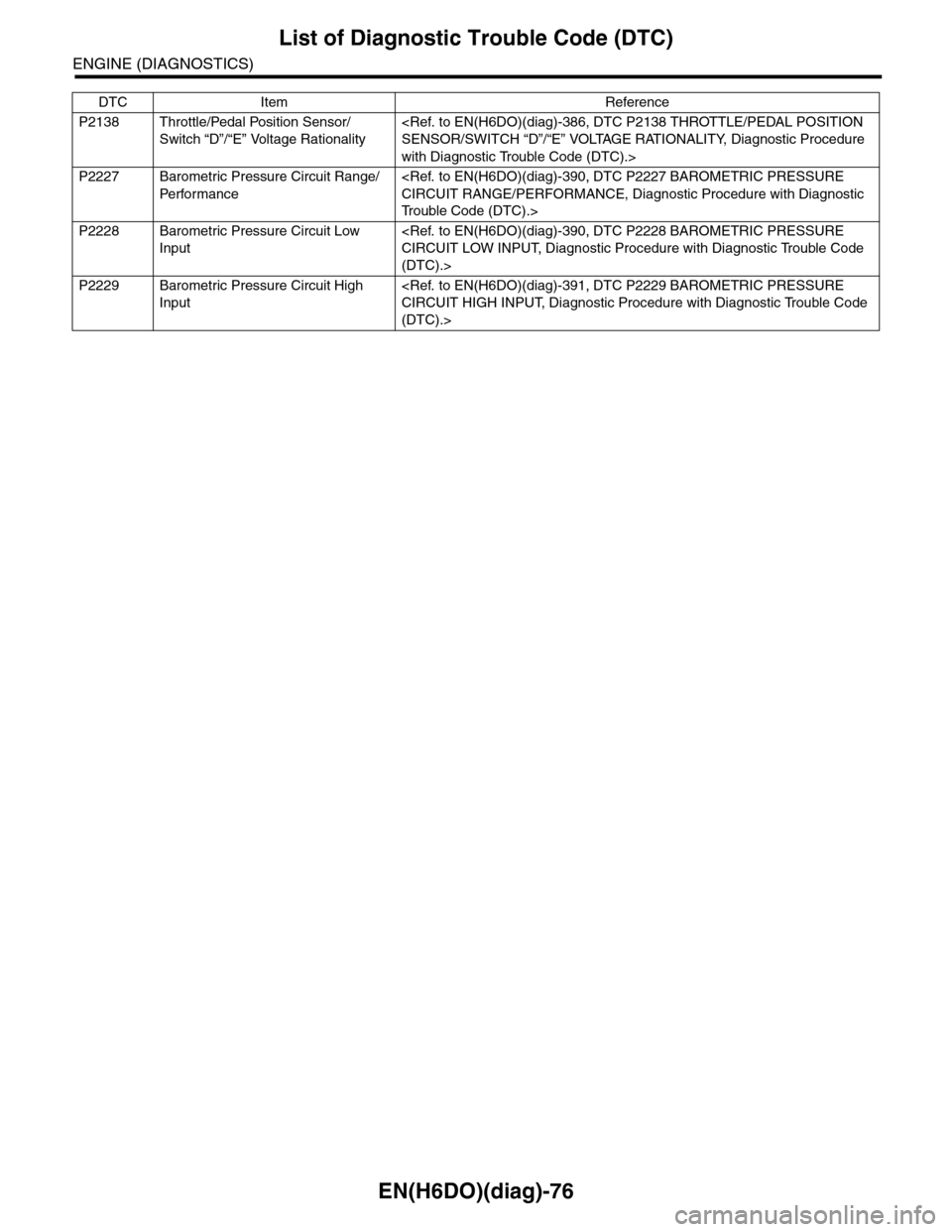
EN(H6DO)(diag)-76
List of Diagnostic Trouble Code (DTC)
ENGINE (DIAGNOSTICS)
P2138 Throttle/Pedal Position Sensor/
Switch “D”/“E” Voltage Rationality
with Diagnostic Trouble Code (DTC).>
P2227 Barometric Pressure Circuit Range/
Pe r fo r ma nc e
Tr o u b l e C o d e ( D T C ) . >
P2228 Barometric Pressure Circuit Low
Input
(DTC).>
P2229 Barometric Pressure Circuit High
Input
(DTC).>
DTC Item Reference
Page 1246 of 2453
EN(H6DO)(diag)-85
Diagnostic Procedure with Diagnostic Trouble Code (DTC)
ENGINE (DIAGNOSTICS)
G: DTC P0030 HO2S HEATER CONTROL CIRCUIT (BANK 1 SENSOR 1)
DTC DETECTING CONDITION:
•Detected when two consecutive driving cycles with fault occur.
•GENERAL DESCRIPTION
CAUTION:
After repair or replacement of faulty parts, perform Clear Memory Mode
Page 1247 of 2453
EN(H6DO)(diag)-86
Diagnostic Procedure with Diagnostic Trouble Code (DTC)
ENGINE (DIAGNOSTICS)
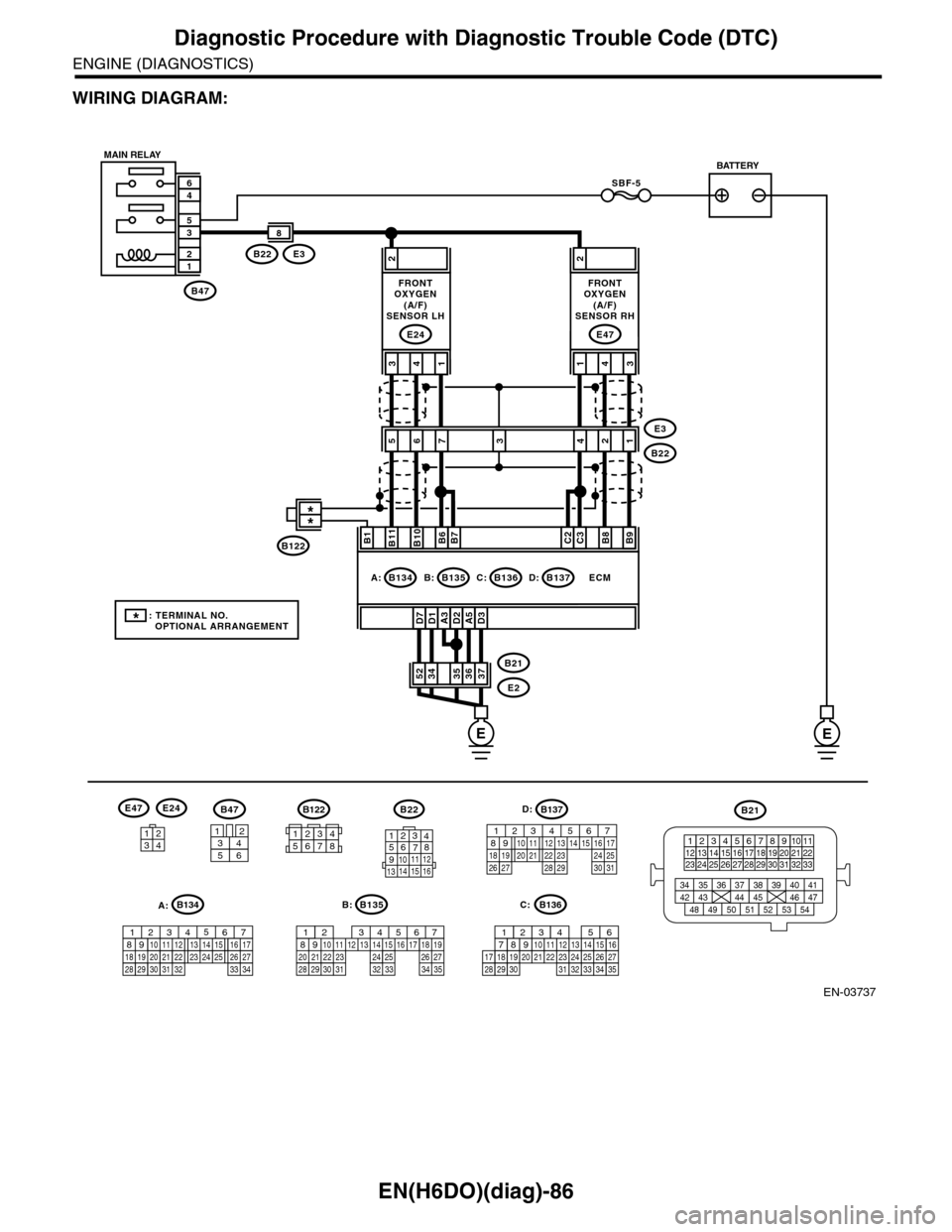
WIRING DIAGRAM:
EN-03737
SBF-5
B47
12
35
46
A3D1D7D2A5D3
2
3736353452B21
E2
ECM
B11B1B10B6B7C2C3B8B9
413
E24
2
431
E47
E3B22
8
56E3
B222134
B47
3456
12
B22
1234567891011 121314 15 16
3412
E47E24
B135
567821943102422 23 2511 12 13 14 1526 2728
16 17 18 1920 2129 30 31 32 33 34 35
B:
B21
123412131415567816171819910 1120212223 24 25 2627 28 29 3031 32 33
3534 37363938 41404342 4445 47464948 51505352 54
EE
B135B:B136C:B137D:B134A:
7
FRONTOXYGEN(A/F)SENSOR LH
FRONTOXYGEN(A/F)SENSOR RH
MAIN RELAYBATTERY
B136
16101112131415252430
9871718192028212223293231
123456
2726333435
C:
B137
85610 11 12 13 14 157213416
3019 20 2228 29
91718 2521 23 243126 27
D:B122
34561278
*: TERMINAL NO. OPTIONAL ARRANGEMENT
**
B122
A:B134
85610 11 12 13 14 157213416
3019 20 2228 29
91718252123 24323126 2733 34
Page 1248 of 2453
EN(H6DO)(diag)-87
Diagnostic Procedure with Diagnostic Trouble Code (DTC)
ENGINE (DIAGNOSTICS)
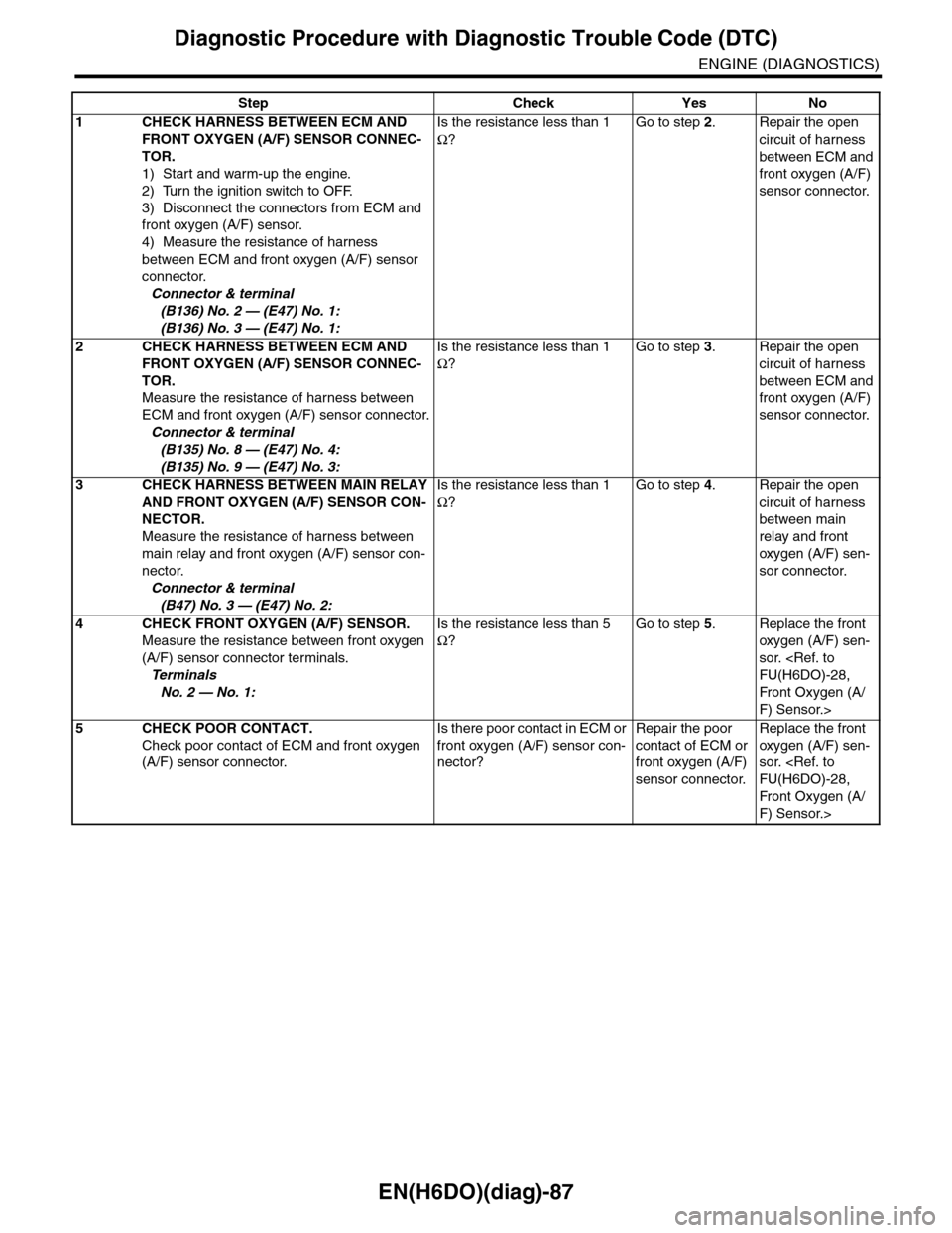
Step Check Yes No
1CHECK HARNESS BETWEEN ECM AND
FRONT OXYGEN (A/F) SENSOR CONNEC-
TOR.
1) Start and warm-up the engine.
2) Turn the ignition switch to OFF.
3) Disconnect the connectors from ECM and
front oxygen (A/F) sensor.
4) Measure the resistance of harness
between ECM and front oxygen (A/F) sensor
connector.
Connector & terminal
(B136) No. 2 — (E47) No. 1:
(B136) No. 3 — (E47) No. 1:
Is the resistance less than 1
Ω?
Go to step 2.Repair the open
circuit of harness
between ECM and
front oxygen (A/F)
sensor connector.
2CHECK HARNESS BETWEEN ECM AND
FRONT OXYGEN (A/F) SENSOR CONNEC-
TOR.
Measure the resistance of harness between
ECM and front oxygen (A/F) sensor connector.
Connector & terminal
(B135) No. 8 — (E47) No. 4:
(B135) No. 9 — (E47) No. 3:
Is the resistance less than 1
Ω?
Go to step 3.Repair the open
circuit of harness
between ECM and
front oxygen (A/F)
sensor connector.
3CHECK HARNESS BETWEEN MAIN RELAY
AND FRONT OXYGEN (A/F) SENSOR CON-
NECTOR.
Measure the resistance of harness between
main relay and front oxygen (A/F) sensor con-
nector.
Connector & terminal
(B47) No. 3 — (E47) No. 2:
Is the resistance less than 1
Ω?
Go to step 4.Repair the open
circuit of harness
between main
relay and front
oxygen (A/F) sen-
sor connector.
4CHECK FRONT OXYGEN (A/F) SENSOR.
Measure the resistance between front oxygen
(A/F) sensor connector terminals.
Te r m i n a l s
No. 2 — No. 1:
Is the resistance less than 5
Ω?
Go to step 5.Replace the front
oxygen (A/F) sen-
sor.
Fr o nt Ox yg en ( A /
F) Sensor.>
5CHECK POOR CONTACT.
Check poor contact of ECM and front oxygen
(A/F) sensor connector.
Is there poor contact in ECM or
front oxygen (A/F) sensor con-
nector?
Repair the poor
contact of ECM or
front oxygen (A/F)
sensor connector.
Replace the front
oxygen (A/F) sen-
sor.
Fr o nt Ox yg en ( A /
F) Sensor.>
Page 1249 of 2453
EN(H6DO)(diag)-88
Diagnostic Procedure with Diagnostic Trouble Code (DTC)
ENGINE (DIAGNOSTICS)
H: DTC P0031 HO2S HEATER CONTROL CIRCUIT LOW (BANK 1 SENSOR 1)
DTC DETECTING CONDITION:
•Immediately at fault recognition
•GENERAL DESCRIPTION
CAUTION:
After repair or replacement of faulty parts, perform Clear Memory Mode
Page 1250 of 2453
EN(H6DO)(diag)-89
Diagnostic Procedure with Diagnostic Trouble Code (DTC)
ENGINE (DIAGNOSTICS)
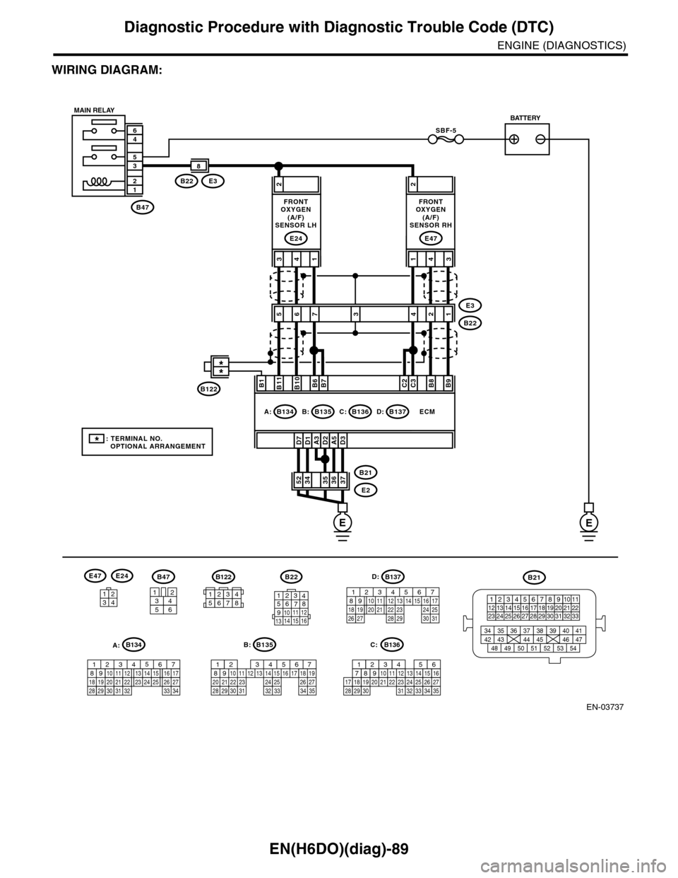
WIRING DIAGRAM:
EN-03737
SBF-5
B47
12
35
46
A3D1D7D2A5D3
2
3736353452B21
E2
ECM
B11B1B10B6B7C2C3B8B9
413
E24
2
431
E47
E3B22
8
56E3
B222134
B47
3456
12
B22
1234567891011 121314 15 16
3412
E47E24
B135
567821943102422 23 2511 12 13 14 1526 2728
16 17 18 1920 2129 30 31 32 33 34 35
B:
B21
123412131415567816171819910 1120212223 24 25 2627 28 29 3031 32 33
3534 37363938 41404342 4445 47464948 51505352 54
EE
B135B:B136C:B137D:B134A:
7
FRONTOXYGEN(A/F)SENSOR LH
FRONTOXYGEN(A/F)SENSOR RH
MAIN RELAYBATTERY
B136
16101112131415252430
9871718192028212223293231
123456
2726333435
C:
B137
85610 11 12 13 14 157213416
3019 20 2228 29
91718 2521 23 243126 27
D:B122
34561278
*: TERMINAL NO. OPTIONAL ARRANGEMENT
**
B122
A:B134
85610 11 12 13 14 157213416
3019 20 2228 29
91718252123 24323126 2733 34
Page 1251 of 2453
EN(H6DO)(diag)-90
Diagnostic Procedure with Diagnostic Trouble Code (DTC)
ENGINE (DIAGNOSTICS)
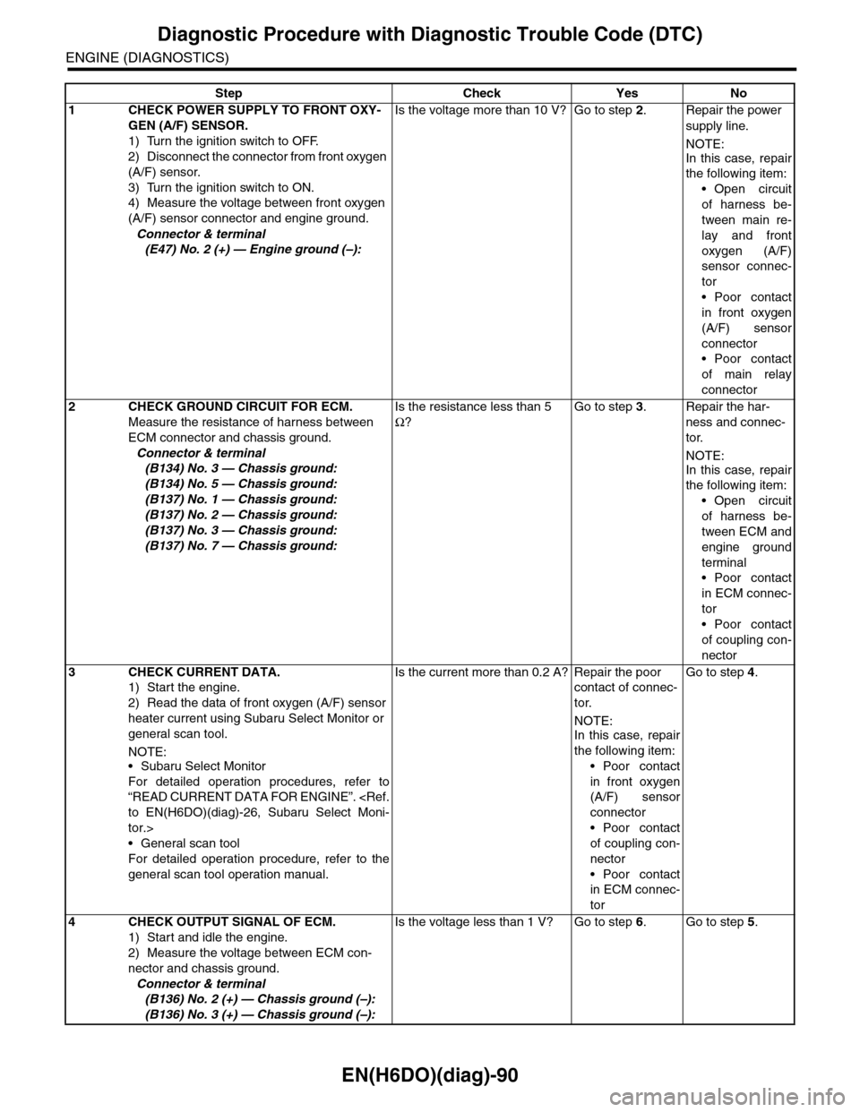
Step Check Yes No
1 CHECK POWER SUPPLY TO FRONT OXY-
GEN (A/F) SENSOR.
1) Turn the ignition switch to OFF.
2) Disconnect the connector from front oxygen
(A/F) sensor.
3) Turn the ignition switch to ON.
4) Measure the voltage between front oxygen
(A/F) sensor connector and engine ground.
Connector & terminal
(E47) No. 2 (+) — Engine ground (–):
Is the voltage more than 10 V? Go to step 2.Repair the power
supply line.
NOTE:
In this case, repair
the following item:
•Open circuit
of harness be-
tween main re-
lay and front
oxygen (A/F)
sensor connec-
tor
•Poor contact
in front oxygen
(A/F) sensor
connector
•Poor contact
of main relay
connector
2CHECK GROUND CIRCUIT FOR ECM.
Measure the resistance of harness between
ECM connector and chassis ground.
Connector & terminal
(B134) No. 3 — Chassis ground:
(B134) No. 5 — Chassis ground:
(B137) No. 1 — Chassis ground:
(B137) No. 2 — Chassis ground:
(B137) No. 3 — Chassis ground:
(B137) No. 7 — Chassis ground:
Is the resistance less than 5
Ω?
Go to step 3.Repair the har-
ness and connec-
tor.
NOTE:
In this case, repair
the following item:
•Open circuit
of harness be-
tween ECM and
engine ground
terminal
•Poor contact
in ECM connec-
tor
•Poor contact
of coupling con-
nector
3CHECK CURRENT DATA.
1) Start the engine.
2) Read the data of front oxygen (A/F) sensor
heater current using Subaru Select Monitor or
general scan tool.
NOTE:•Subaru Select Monitor
For detailed operation procedures, refer to
“READ CURRENT DATA FOR ENGINE”.
tor.>
•General scan tool
For detailed operation procedure, refer to the
general scan tool operation manual.
Is the current more than 0.2 A? Repair the poor
contact of connec-
tor.
NOTE:
In this case, repair
the following item:
•Poor contact
in front oxygen
(A/F) sensor
connector
•Poor contact
of coupling con-
nector
•Poor contact
in ECM connec-
tor
Go to step 4.
4CHECK OUTPUT SIGNAL OF ECM.
1) Start and idle the engine.
2) Measure the voltage between ECM con-
nector and chassis ground.
Connector & terminal
(B136) No. 2 (+) — Chassis ground (–):
(B136) No. 3 (+) — Chassis ground (–):
Is the voltage less than 1 V? Go to step 6.Go to step 5.