sensor SUBARU TRIBECA 2009 1.G Service Workshop Manual
[x] Cancel search | Manufacturer: SUBARU, Model Year: 2009, Model line: TRIBECA, Model: SUBARU TRIBECA 2009 1.GPages: 2453, PDF Size: 46.32 MB
Page 1559 of 2453
EX(H6DO)-5
Front Exhaust Pipe
EXHAUST
B: INSTALLATION
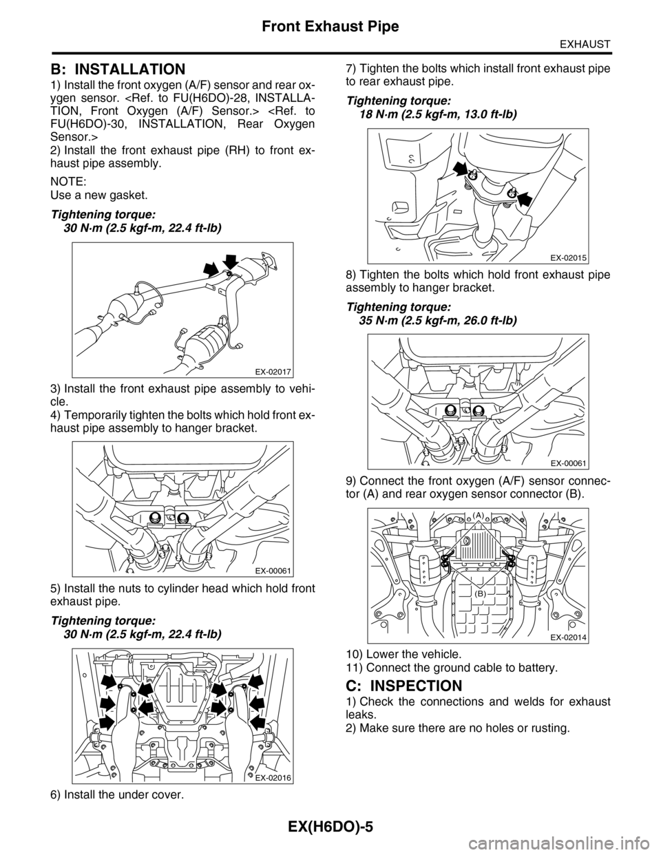
1) Install the front oxygen (A/F) sensor and rear ox-
ygen sensor.
Sensor.>
2) Install the front exhaust pipe (RH) to front ex-
haust pipe assembly.
NOTE:
Use a new gasket.
Tightening torque:
30 N·m (2.5 kgf-m, 22.4 ft-lb)
3) Install the front exhaust pipe assembly to vehi-
cle.
4) Temporarily tighten the bolts which hold front ex-
haust pipe assembly to hanger bracket.
5) Install the nuts to cylinder head which hold front
exhaust pipe.
Tightening torque:
30 N·m (2.5 kgf-m, 22.4 ft-lb)
6) Install the under cover.
7) Tighten the bolts which install front exhaust pipe
to rear exhaust pipe.
Tightening torque:
18 N·m (2.5 kgf-m, 13.0 ft-lb)
8) Tighten the bolts which hold front exhaust pipe
assembly to hanger bracket.
Tightening torque:
35 N·m (2.5 kgf-m, 26.0 ft-lb)
9) Connect the front oxygen (A/F) sensor connec-
tor (A) and rear oxygen sensor connector (B).
10) Lower the vehicle.
11) Connect the ground cable to battery.
C: INSPECTION
1) Check the connections and welds for exhaust
leaks.
2) Make sure there are no holes or rusting.
EX-02017
EX-00061
EX-02016
EX-02015
EX-00061
EX-02014
(A)
(B)
Page 1565 of 2453
FU(H6DO)-4
General Description
FUEL INJECTION (FUEL SYSTEMS)
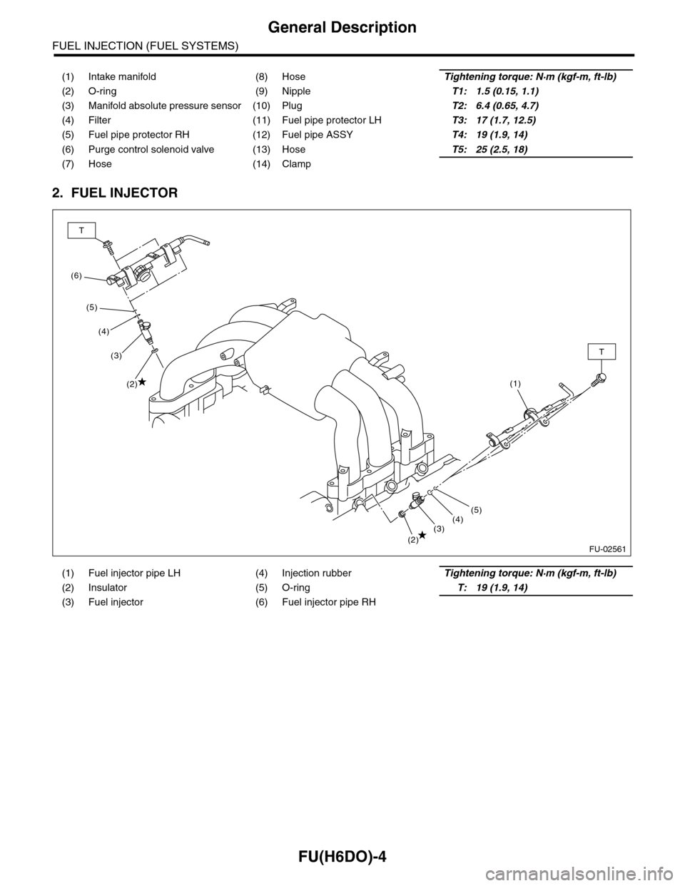
2. FUEL INJECTOR
(1) Intake manifold (8) HoseTightening torque: N·m (kgf-m, ft-lb)
(2) O-ring (9) NippleT1: 1.5 (0.15, 1.1)
(3) Manifold absolute pressure sensor (10) PlugT2: 6.4 (0.65, 4.7)
(4) Filter (11) Fuel pipe protector LHT3: 17 (1.7, 12.5)
(5) Fuel pipe protector RH (12) Fuel pipe ASSYT4: 19 (1.9, 14)
(6) Purge control solenoid valve (13) HoseT5: 25 (2.5, 18)
(7) Hose (14) Clamp
(1) Fuel injector pipe LH (4) Injection rubberTightening torque: N·m (kgf-m, ft-lb)
(2) Insulator (5) O-ringT: 19 (1.9, 14)
(3) Fuel injector (6) Fuel injector pipe RH
FU-02561
(6)
T
T
(5)
(4)
(3)
(2)
(2)(3)(4)(5)
(1)
Page 1567 of 2453
FU(H6DO)-6
General Description
FUEL INJECTION (FUEL SYSTEMS)
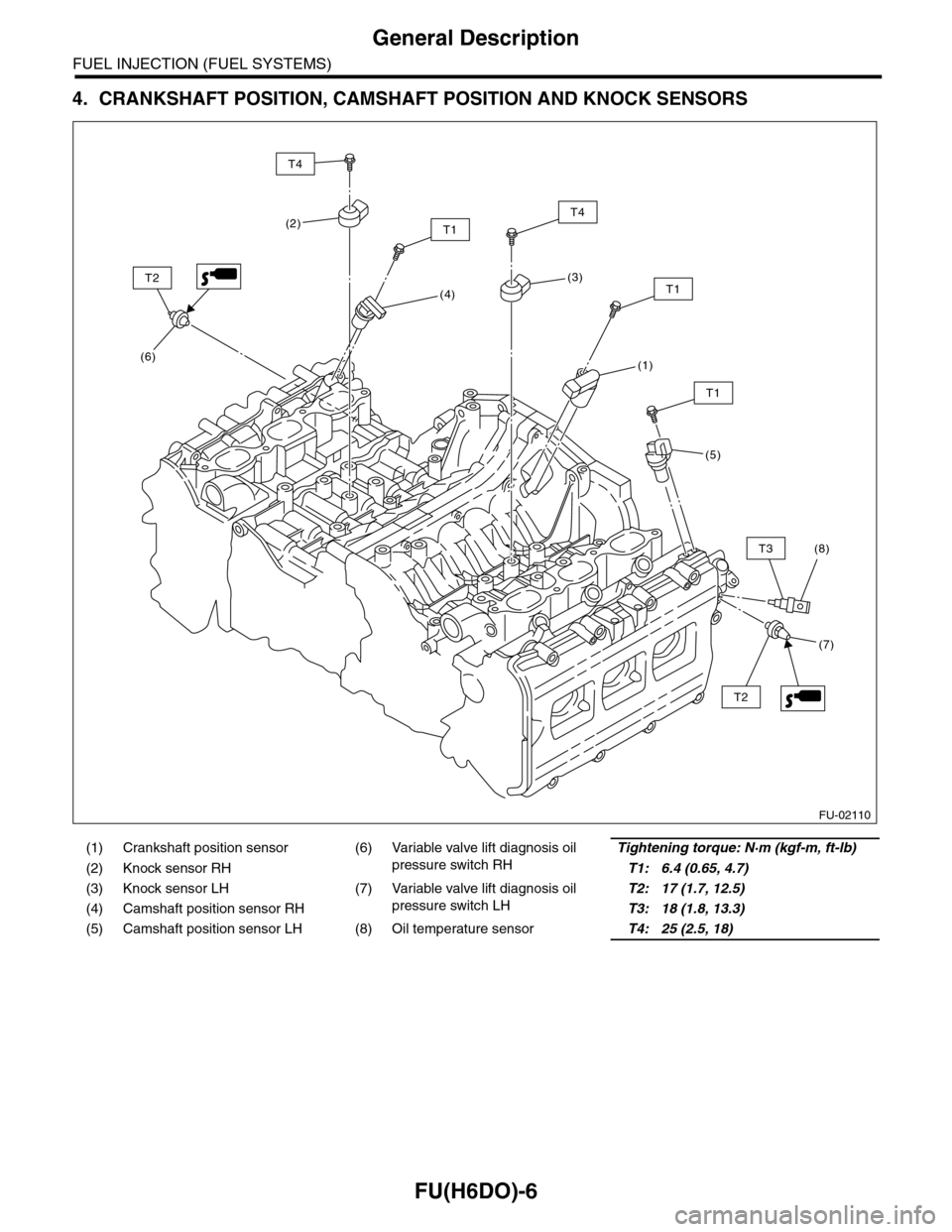
4. CRANKSHAFT POSITION, CAMSHAFT POSITION AND KNOCK SENSORS
(1) Crankshaft position sensor (6) Variable valve lift diagnosis oil
pressure switch RH
Tightening torque: N·m (kgf-m, ft-lb)
(2) Knock sensor RHT1: 6.4 (0.65, 4.7)
(3) Knock sensor LH (7) Variable valve lift diagnosis oil
pressure switch LH
T2: 17 (1.7, 12.5)
(4) Camshaft position sensor RHT3: 18 (1.8, 13.3)
(5) Camshaft position sensor LH (8) Oil temperature sensorT4: 25 (2.5, 18)
FU-02110
(6)
(4)
T2
T1
(3)
T4
(1)
(8)
T1
T3
(5)
T1
(2)
T4
(7)
T2
Page 1569 of 2453
FU(H6DO)-8
General Description
FUEL INJECTION (FUEL SYSTEMS)
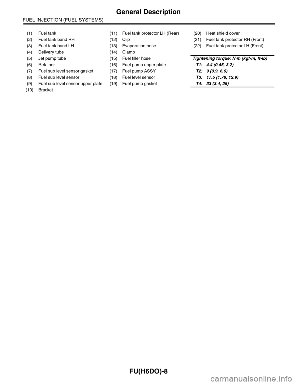
(1) Fuel tank (11) Fuel tank protector LH (Rear) (20) Heat shield cover
(2) Fuel tank band RH (12) Clip (21) Fuel tank protector RH (Front)
(3) Fuel tank band LH (13) Evaporation hose (22) Fuel tank protector LH (Front)
(4) Delivery tube (14) Clamp
(5) Jet pump tube (15) Fuel filler hoseTightening torque: N·m (kgf-m, ft-lb)
(6) Retainer (16) Fuel pump upper plateT1: 4.4 (0.45, 3.2)
(7) Fuel sub level sensor gasket (17) Fuel pump ASSYT2: 9 (0.9, 6.6)
(8) Fuel sub level sensor (18) Fuel level sensorT3: 17.5 (1.78, 12.9)
(9) Fuel sub level sensor upper plate (19) Fuel pump gasketT4: 33 (3.4, 25)
(10) Bracket
Page 1570 of 2453
FU(H6DO)-9
General Description
FUEL INJECTION (FUEL SYSTEMS)
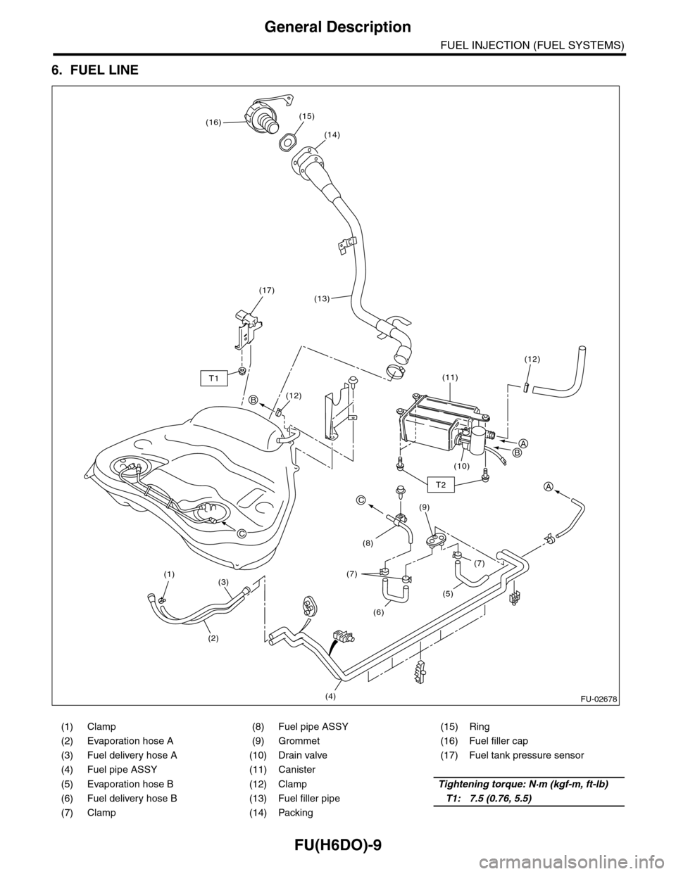
6. FUEL LINE
(1) Clamp (8) Fuel pipe ASSY (15) Ring
(2) Evaporation hose A (9) Grommet (16) Fuel filler cap
(3) Fuel delivery hose A (10) Drain valve (17) Fuel tank pressure sensor
(4) Fuel pipe ASSY (11) Canister
(5) Evaporation hose B (12) ClampTightening torque: N·m (kgf-m, ft-lb)
(6) Fuel delivery hose B (13) Fuel filler pipeT1: 7.5 (0.76, 5.5)
(7) Clamp (14) Packing
C
C
A
AB
B
(15)
(13)(17)
(16)
(14)
T1
T2
(5)
(6)
(4)
(7)(7)
(8)
(9)
(11)
(12)
(12)
(10)
(2)
(3)(1)
FU-02678
Page 1571 of 2453
FU(H6DO)-10
General Description
FUEL INJECTION (FUEL SYSTEMS)
C: CAUTION
•Wear work clothing, including a cap, protective goggles and protective shoes during operation.
•Remove contamination including dirt and corrosion before removal, installation or disassembly.
•Keep the disassembled parts in order and protect them from dust and dirt.
•Before removal, installation or disassembly, be sure to clarify the failure. Avoid unnecessary removal, in-
stallation, disassembly and replacement.
•Be careful not to burn yourself, because each part on the vehicle is hot after running.
•Be sure to tighten fasteners including bolts and nuts to the specified torque.
•Place shop jacks or rigid racks at the specified points.
•Before disconnecting connectors of sensors or units, be sure to disconnect the ground cable from the bat-
tery.
•Place “NO FIRE” signs near the working area.
•Be careful not to spill fuel on the floor.
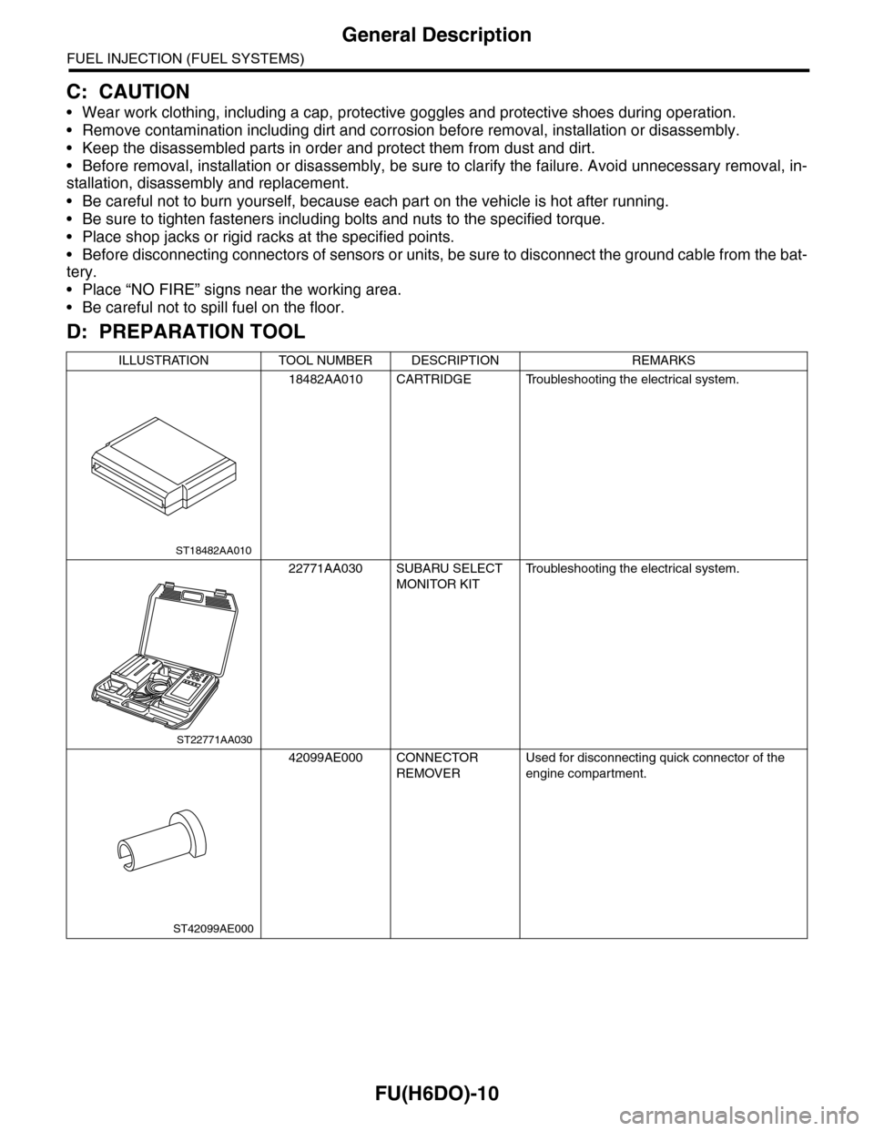
D: PREPARATION TOOL
ILLUSTRATION TOOL NUMBER DESCRIPTION REMARKS
18482AA010 CARTRIDGE Troubleshooting the electrical system.
22771AA030 SUBARU SELECT
MONITOR KIT
Tr o u b l e s h o o t i n g t h e e l e c t r i c a l s y s t e m .
42099AE000 CONNECTOR
REMOVER
Used for disconnecting quick connector of the
engine compartment.
ST18482AA010
ST22771AA030
ST42099AE000
Page 1572 of 2453
FU(H6DO)-11
Throttle Body
FUEL INJECTION (FUEL SYSTEMS)
2. Throttle Body
A: REMOVAL
1) Remove the collector cover.
2) Disconnect the ground cable from battery.
3) Remove the air intake chamber.
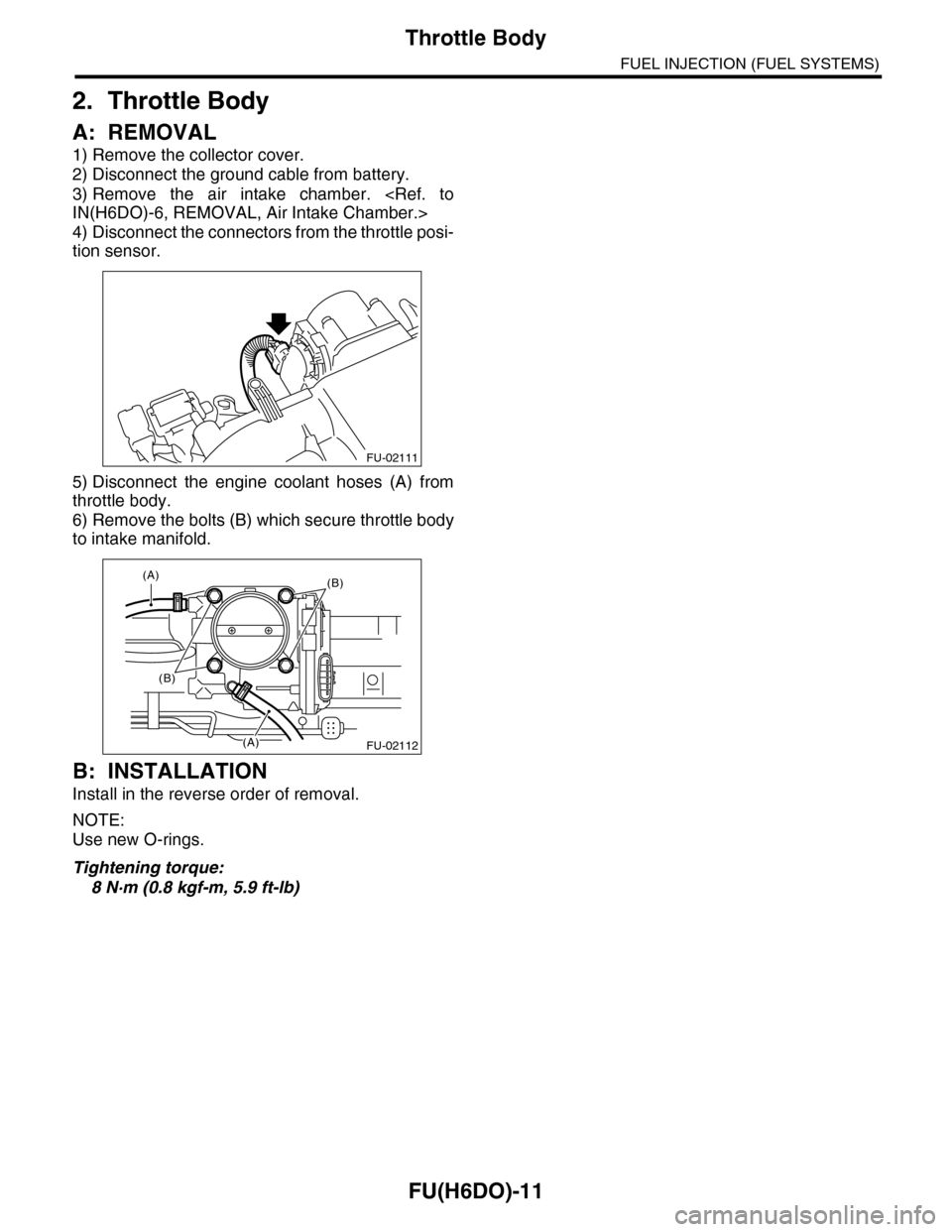
4) Disconnect the connectors from the throttle posi-
tion sensor.
5) Disconnect the engine coolant hoses (A) from
throttle body.
6) Remove the bolts (B) which secure throttle body
to intake manifold.
B: INSTALLATION
Install in the reverse order of removal.
NOTE:
Use new O-rings.
Tightening torque:
8 N·m (0.8 kgf-m, 5.9 ft-lb)
FU-02111
FU-02112
(A)(B)
(B)
(A)
Page 1576 of 2453
FU(H6DO)-15
Intake Manifold
FUEL INJECTION (FUEL SYSTEMS)
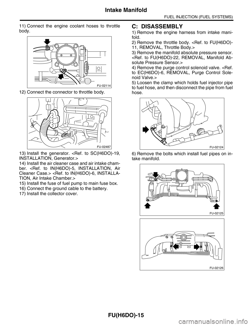
11) Connect the engine coolant hoses to throttle
body.
12) Connect the connector to throttle body.
13) Install the generator.
14) Install the air cleaner case and air intake cham-
ber.
15) Install the fuse of fuel pump to main fuse box.
16) Connect the ground cable to the battery.
17) Install the collector cover.
C: DISASSEMBLY
1) Remove the engine harness from intake mani-
fold.
2) Remove the throttle body.
3) Remove the manifold absolute pressure sensor.
4) Remove the purge control solenoid valve.
noid Valve.>
5) Loosen the clamp which holds fuel injector pipe
to fuel hose, and then disconnect the pipe from fuel
hose.
6) Remove the bolts which install fuel pipes on in-
take manifold.
FU-02114
FU-02487FU-02124
FU-02125
FU-02126
Page 1577 of 2453
FU(H6DO)-16
Intake Manifold
FUEL INJECTION (FUEL SYSTEMS)
D: ASSEMBLY
NOTE:
When assembling the nipple, apply liquid gasket.
Liquid gasket:
THREE BOND 1105 (Part No.004403010)
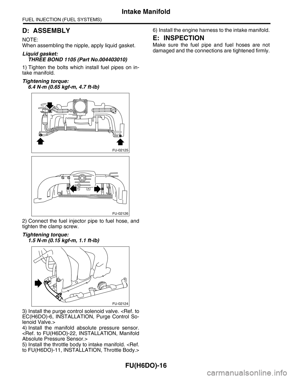
1) Tighten the bolts which install fuel pipes on in-
take manifold.
Tightening torque:
6.4 N·m (0.65 kgf-m, 4.7 ft-lb)
2) Connect the fuel injector pipe to fuel hose, and
tighten the clamp screw.
Tightening torque:
1.5 N·m (0.15 kgf-m, 1.1 ft-lb)
3) Install the purge control solenoid valve.
lenoid Valve.>
4) Install the manifold absolute pressure sensor.
5) Install the throttle body to intake manifold.
6) Install the engine harness to the intake manifold.
E: INSPECTION
Make sure the fuel pipe and fuel hoses are not
damaged and the connections are tightened firmly.
FU-02125
FU-02126
FU-02124
Page 1578 of 2453
FU(H6DO)-17
Engine Coolant Temperature Sensor
FUEL INJECTION (FUEL SYSTEMS)
4. Engine Coolant Temperature
Sensor
A: REMOVAL
1) Remove the collector cover.
2) Disconnect the ground cable from battery.
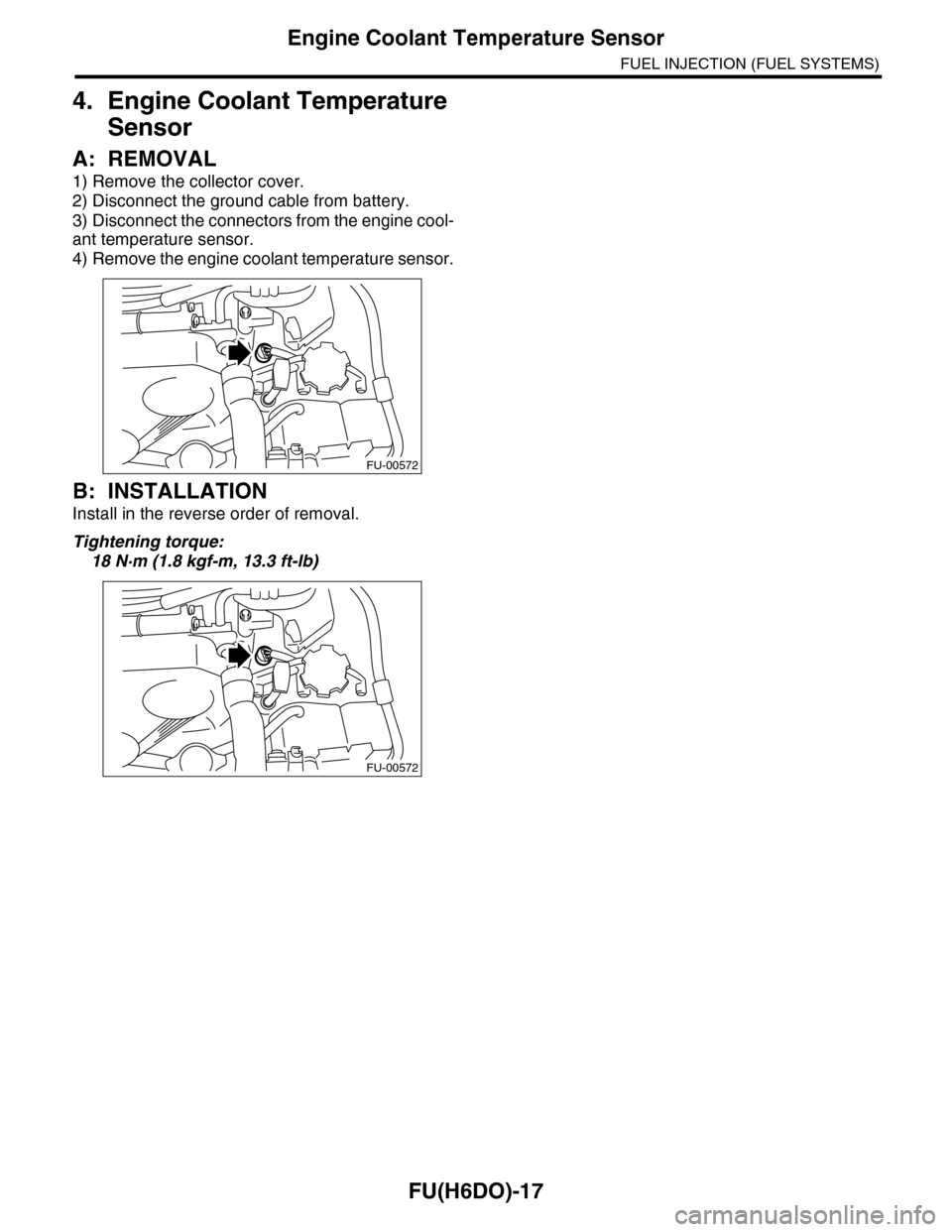
3) Disconnect the connectors from the engine cool-
ant temperature sensor.
4) Remove the engine coolant temperature sensor.
B: INSTALLATION
Install in the reverse order of removal.
Tightening torque:
18 N·m (1.8 kgf-m, 13.3 ft-lb)
FU-00572
FU-00572