sensor SUBARU TRIBECA 2009 1.G Service Workshop Manual
[x] Cancel search | Manufacturer: SUBARU, Model Year: 2009, Model line: TRIBECA, Model: SUBARU TRIBECA 2009 1.GPages: 2453, PDF Size: 46.32 MB
Page 1537 of 2453
EN(H6DO)(diag)-376
Diagnostic Procedure with Diagnostic Trouble Code (DTC)
ENGINE (DIAGNOSTICS)
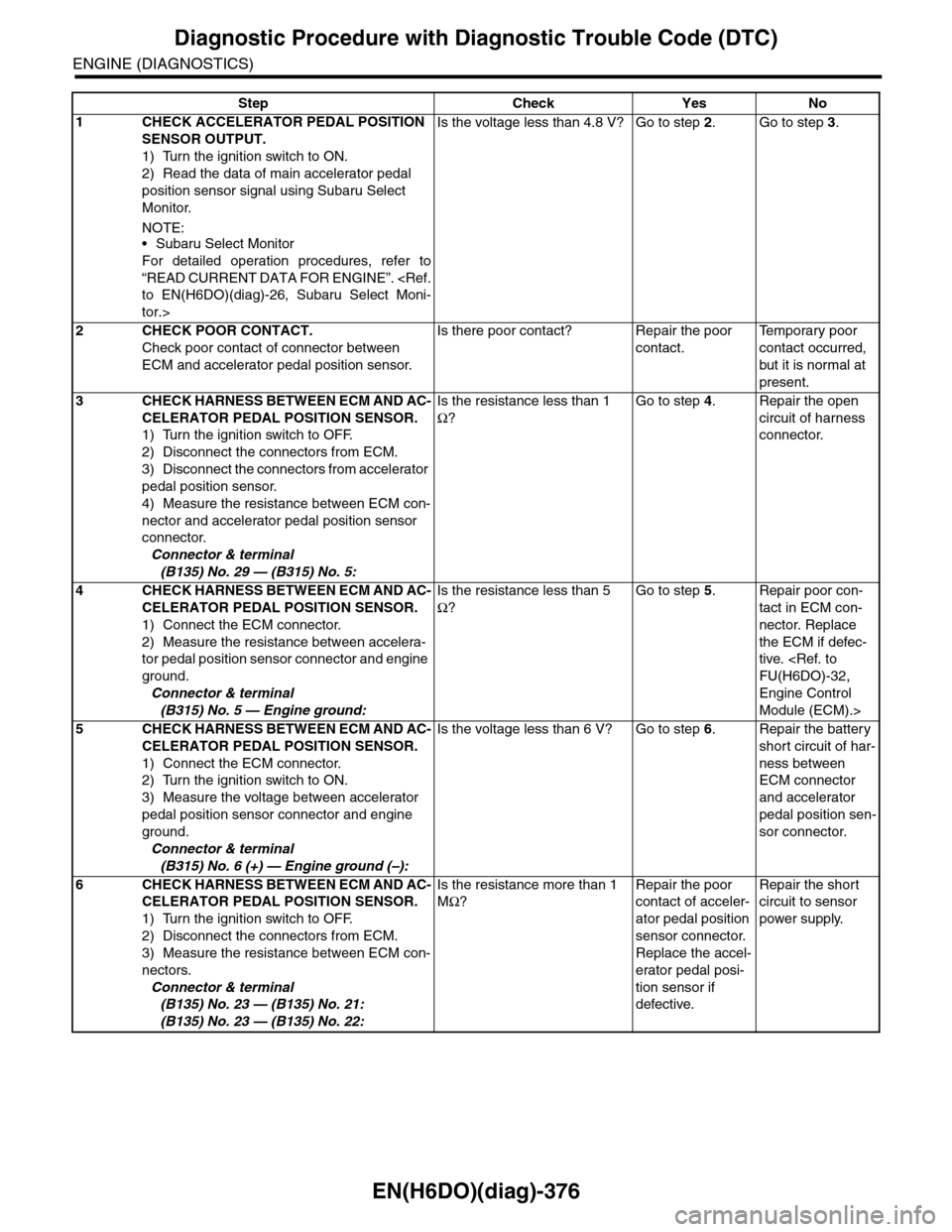
Step Check Yes No
1CHECK ACCELERATOR PEDAL POSITION
SENSOR OUTPUT.
1) Turn the ignition switch to ON.
2) Read the data of main accelerator pedal
position sensor signal using Subaru Select
Monitor.
NOTE:•Subaru Select Monitor
For detailed operation procedures, refer to
“READ CURRENT DATA FOR ENGINE”.
tor.>
Is the voltage less than 4.8 V? Go to step 2.Go to step 3.
2CHECK POOR CONTACT.
Check poor contact of connector between
ECM and accelerator pedal position sensor.
Is there poor contact? Repair the poor
contact.
Te m p o r a r y p o o r
contact occurred,
but it is normal at
present.
3CHECK HARNESS BETWEEN ECM AND AC-
CELERATOR PEDAL POSITION SENSOR.
1) Turn the ignition switch to OFF.
2) Disconnect the connectors from ECM.
3) Disconnect the connectors from accelerator
pedal position sensor.
4) Measure the resistance between ECM con-
nector and accelerator pedal position sensor
connector.
Connector & terminal
(B135) No. 29 — (B315) No. 5:
Is the resistance less than 1
Ω?
Go to step 4.Repair the open
circuit of harness
connector.
4CHECK HARNESS BETWEEN ECM AND AC-
CELERATOR PEDAL POSITION SENSOR.
1) Connect the ECM connector.
2) Measure the resistance between accelera-
tor pedal position sensor connector and engine
ground.
Connector & terminal
(B315) No. 5 — Engine ground:
Is the resistance less than 5
Ω?
Go to step 5.Repair poor con-
tact in ECM con-
nector. Replace
the ECM if defec-
tive.
Engine Control
Module (ECM).>
5CHECK HARNESS BETWEEN ECM AND AC-
CELERATOR PEDAL POSITION SENSOR.
1) Connect the ECM connector.
2) Turn the ignition switch to ON.
3) Measure the voltage between accelerator
pedal position sensor connector and engine
ground.
Connector & terminal
(B315) No. 6 (+) — Engine ground (–):
Is the voltage less than 6 V? Go to step 6.Repair the battery
short circuit of har-
ness between
ECM connector
and accelerator
pedal position sen-
sor connector.
6CHECK HARNESS BETWEEN ECM AND AC-
CELERATOR PEDAL POSITION SENSOR.
1) Turn the ignition switch to OFF.
2) Disconnect the connectors from ECM.
3) Measure the resistance between ECM con-
nectors.
Connector & terminal
(B135) No. 23 — (B135) No. 21:
(B135) No. 23 — (B135) No. 22:
Is the resistance more than 1
MΩ?
Repair the poor
contact of acceler-
ator pedal position
sensor connector.
Replace the accel-
erator pedal posi-
tion sensor if
defective.
Repair the short
circuit to sensor
power supply.
Page 1538 of 2453
EN(H6DO)(diag)-377
Diagnostic Procedure with Diagnostic Trouble Code (DTC)
ENGINE (DIAGNOSTICS)
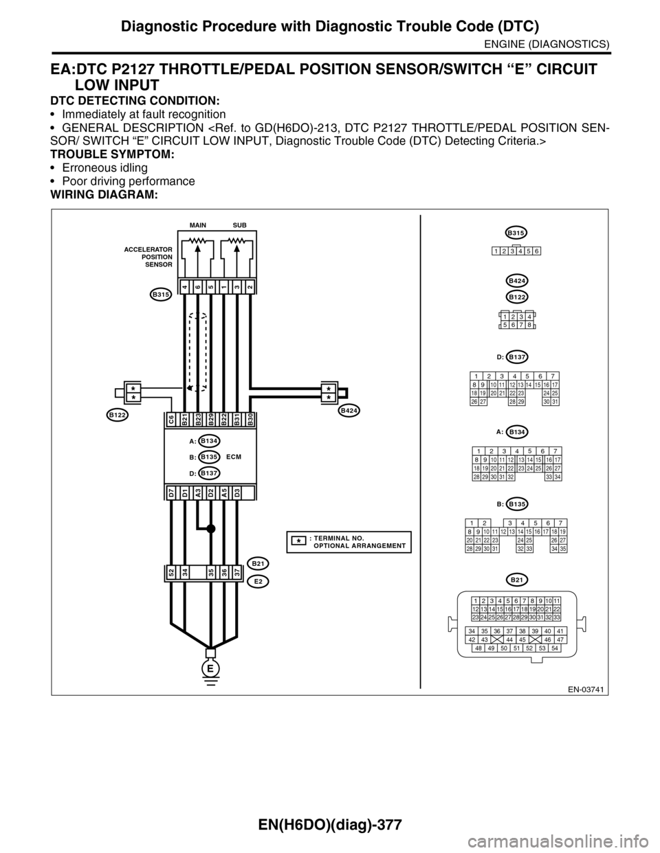
EA:DTC P2127 THROTTLE/PEDAL POSITION SENSOR/SWITCH “E” CIRCUIT
LOW INPUT
DTC DETECTING CONDITION:
•Immediately at fault recognition
•GENERAL DESCRIPTION
TROUBLE SYMPTOM:
•Erroneous idling
•Poor driving performance
WIRING DIAGRAM:
EN-03741
E
ECM
A:B134
B137D:
B424
B315
ACCELERATORPOSITIONSENSOR
**
465132
B21B23B29B22B31B30
A3D2
B21
E2
A5
MAIN SUB
B21
123412131415567816171819910 1120212223 24 25 2627 28 29 3031 32 33
3534 37363938 41404342 4445 47464948 51505352 54
B135
567821943102422 23 2511 12 13 14 1526 2728
16 17 18 1920 2129 30 31 32 33 34 35
B:
B137
5678219431022 2311 12 13 14 1524 2526
16 1718 19 20 2127 28 29 30 31
D:
12345678
B122
B424
D1D7
C6
B:B135
D3
3734355236
B122
B315
123456
**
*: TERMINAL NO. OPTIONAL ARRANGEMENT
B134
85610 11 12 13 14 157213416
3019 20 2228 29
91718252123 24323126 2733 34
A:
Page 1539 of 2453
EN(H6DO)(diag)-378
Diagnostic Procedure with Diagnostic Trouble Code (DTC)
ENGINE (DIAGNOSTICS)
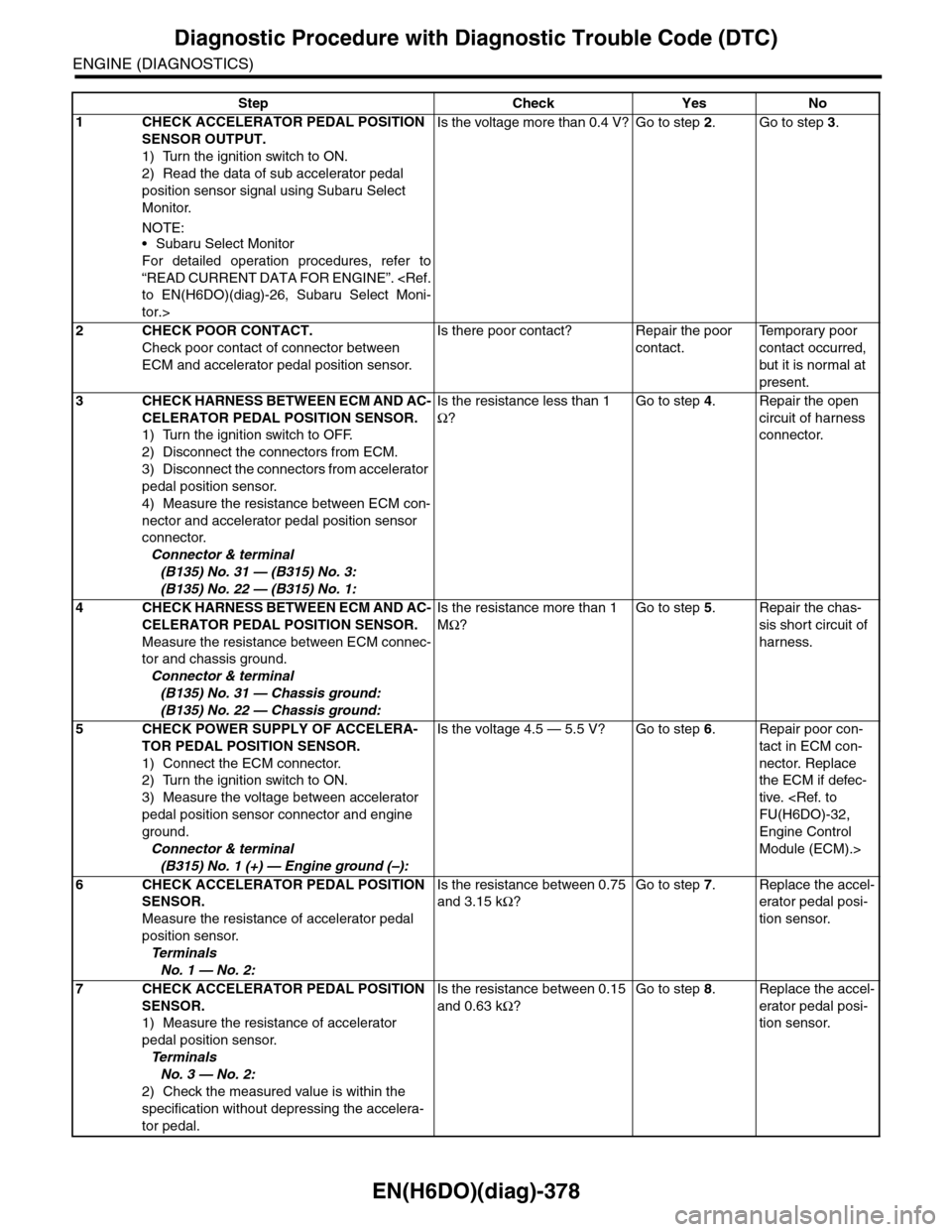
Step Check Yes No
1CHECK ACCELERATOR PEDAL POSITION
SENSOR OUTPUT.
1) Turn the ignition switch to ON.
2) Read the data of sub accelerator pedal
position sensor signal using Subaru Select
Monitor.
NOTE:•Subaru Select Monitor
For detailed operation procedures, refer to
“READ CURRENT DATA FOR ENGINE”.
tor.>
Is the voltage more than 0.4 V? Go to step 2.Go to step 3.
2CHECK POOR CONTACT.
Check poor contact of connector between
ECM and accelerator pedal position sensor.
Is there poor contact? Repair the poor
contact.
Te m p o r a r y p o o r
contact occurred,
but it is normal at
present.
3CHECK HARNESS BETWEEN ECM AND AC-
CELERATOR PEDAL POSITION SENSOR.
1) Turn the ignition switch to OFF.
2) Disconnect the connectors from ECM.
3) Disconnect the connectors from accelerator
pedal position sensor.
4) Measure the resistance between ECM con-
nector and accelerator pedal position sensor
connector.
Connector & terminal
(B135) No. 31 — (B315) No. 3:
(B135) No. 22 — (B315) No. 1:
Is the resistance less than 1
Ω?
Go to step 4.Repair the open
circuit of harness
connector.
4CHECK HARNESS BETWEEN ECM AND AC-
CELERATOR PEDAL POSITION SENSOR.
Measure the resistance between ECM connec-
tor and chassis ground.
Connector & terminal
(B135) No. 31 — Chassis ground:
(B135) No. 22 — Chassis ground:
Is the resistance more than 1
MΩ?
Go to step 5.Repair the chas-
sis short circuit of
harness.
5CHECK POWER SUPPLY OF ACCELERA-
TOR PEDAL POSITION SENSOR.
1) Connect the ECM connector.
2) Turn the ignition switch to ON.
3) Measure the voltage between accelerator
pedal position sensor connector and engine
ground.
Connector & terminal
(B315) No. 1 (+) — Engine ground (–):
Is the voltage 4.5 — 5.5 V? Go to step 6.Repair poor con-
tact in ECM con-
nector. Replace
the ECM if defec-
tive.
Engine Control
Module (ECM).>
6CHECK ACCELERATOR PEDAL POSITION
SENSOR.
Measure the resistance of accelerator pedal
position sensor.
Te r m i n a l s
No. 1 — No. 2:
Is the resistance between 0.75
and 3.15 kΩ?
Go to step 7.Replace the accel-
erator pedal posi-
tion sensor.
7CHECK ACCELERATOR PEDAL POSITION
SENSOR.
1) Measure the resistance of accelerator
pedal position sensor.
Te r m i n a l s
No. 3 — No. 2:
2) Check the measured value is within the
specification without depressing the accelera-
tor pedal.
Is the resistance between 0.15
and 0.63 kΩ?
Go to step 8.Replace the accel-
erator pedal posi-
tion sensor.
Page 1540 of 2453
EN(H6DO)(diag)-379
Diagnostic Procedure with Diagnostic Trouble Code (DTC)
ENGINE (DIAGNOSTICS)
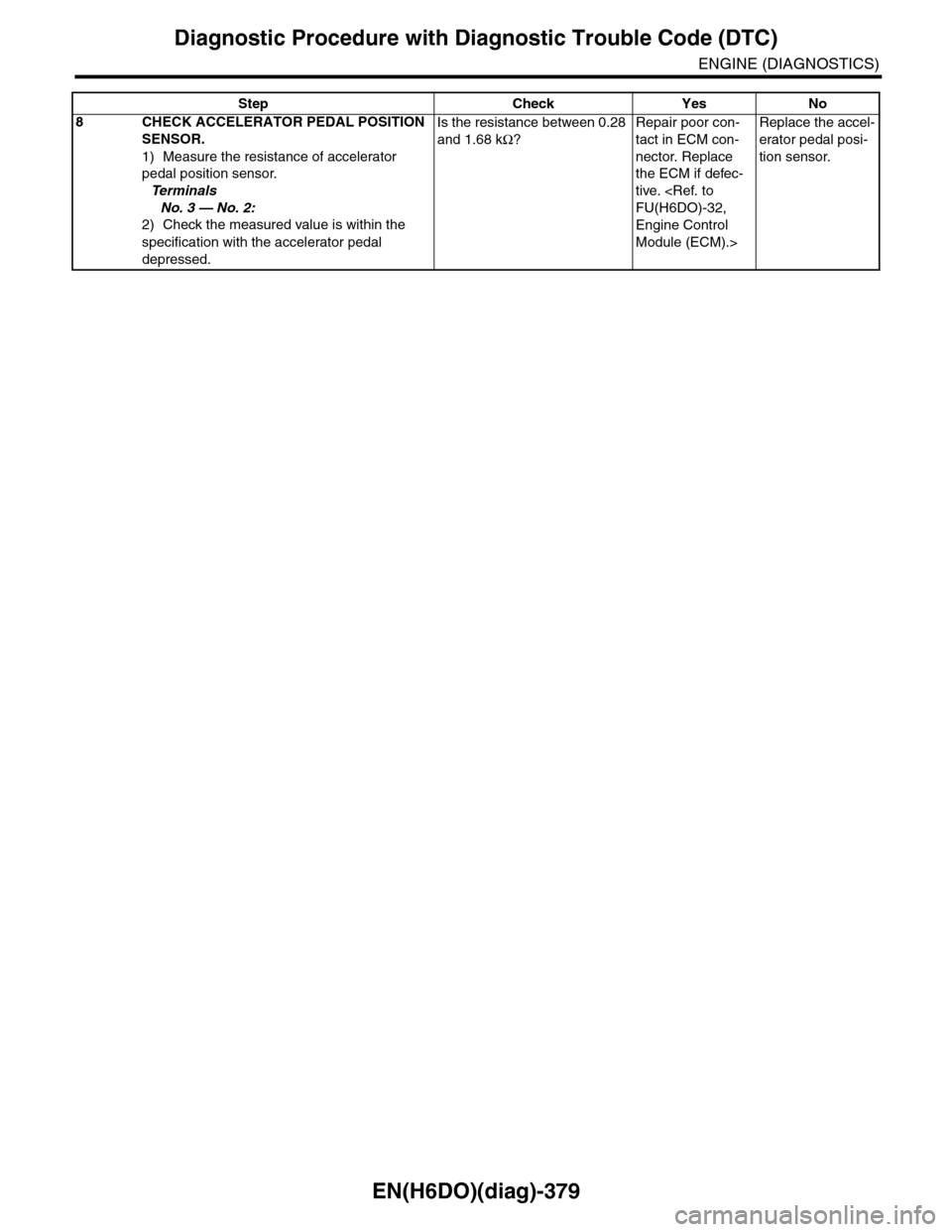
8CHECK ACCELERATOR PEDAL POSITION
SENSOR.
1) Measure the resistance of accelerator
pedal position sensor.
Te r m i n a l s
No. 3 — No. 2:
2) Check the measured value is within the
specification with the accelerator pedal
depressed.
Is the resistance between 0.28
and 1.68 kΩ?
Repair poor con-
tact in ECM con-
nector. Replace
the ECM if defec-
tive.
Engine Control
Module (ECM).>
Replace the accel-
erator pedal posi-
tion sensor.
Step Check Yes No
Page 1541 of 2453
EN(H6DO)(diag)-380
Diagnostic Procedure with Diagnostic Trouble Code (DTC)
ENGINE (DIAGNOSTICS)
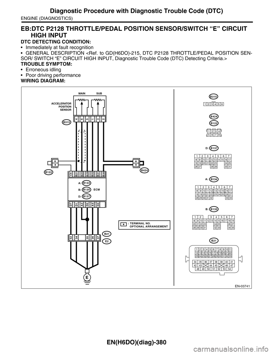
EB:DTC P2128 THROTTLE/PEDAL POSITION SENSOR/SWITCH “E” CIRCUIT
HIGH INPUT
DTC DETECTING CONDITION:
•Immediately at fault recognition
•GENERAL DESCRIPTION
TROUBLE SYMPTOM:
•Erroneous idling
•Poor driving performance
WIRING DIAGRAM:
EN-03741
E
ECM
A:B134
B137D:
B424
B315
ACCELERATORPOSITIONSENSOR
**
465132
B21B23B29B22B31B30
A3D2
B21
E2
A5
MAIN SUB
B21
123412131415567816171819910 1120212223 24 25 2627 28 29 3031 32 33
3534 37363938 41404342 4445 47464948 51505352 54
B135
567821943102422 23 2511 12 13 14 1526 2728
16 17 18 1920 2129 30 31 32 33 34 35
B:
B137
5678219431022 2311 12 13 14 1524 2526
16 1718 19 20 2127 28 29 30 31
D:
12345678
B122
B424
D1D7
C6
B:B135
D3
3734355236
B122
B315
123456
**
*: TERMINAL NO. OPTIONAL ARRANGEMENT
B134
85610 11 12 13 14 157213416
3019 20 2228 29
91718252123 24323126 2733 34
A:
Page 1542 of 2453
EN(H6DO)(diag)-381
Diagnostic Procedure with Diagnostic Trouble Code (DTC)
ENGINE (DIAGNOSTICS)
Step Check Yes No
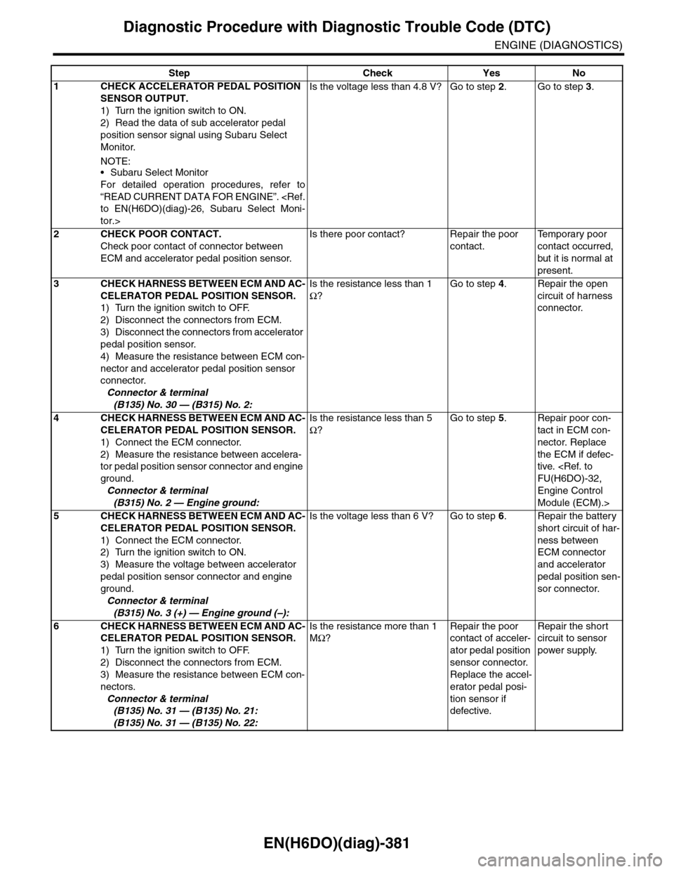
1CHECK ACCELERATOR PEDAL POSITION
SENSOR OUTPUT.
1) Turn the ignition switch to ON.
2) Read the data of sub accelerator pedal
position sensor signal using Subaru Select
Monitor.
NOTE:•Subaru Select Monitor
For detailed operation procedures, refer to
“READ CURRENT DATA FOR ENGINE”.
tor.>
Is the voltage less than 4.8 V? Go to step 2.Go to step 3.
2CHECK POOR CONTACT.
Check poor contact of connector between
ECM and accelerator pedal position sensor.
Is there poor contact? Repair the poor
contact.
Te m p o r a r y p o o r
contact occurred,
but it is normal at
present.
3CHECK HARNESS BETWEEN ECM AND AC-
CELERATOR PEDAL POSITION SENSOR.
1) Turn the ignition switch to OFF.
2) Disconnect the connectors from ECM.
3) Disconnect the connectors from accelerator
pedal position sensor.
4) Measure the resistance between ECM con-
nector and accelerator pedal position sensor
connector.
Connector & terminal
(B135) No. 30 — (B315) No. 2:
Is the resistance less than 1
Ω?
Go to step 4.Repair the open
circuit of harness
connector.
4CHECK HARNESS BETWEEN ECM AND AC-
CELERATOR PEDAL POSITION SENSOR.
1) Connect the ECM connector.
2) Measure the resistance between accelera-
tor pedal position sensor connector and engine
ground.
Connector & terminal
(B315) No. 2 — Engine ground:
Is the resistance less than 5
Ω?
Go to step 5.Repair poor con-
tact in ECM con-
nector. Replace
the ECM if defec-
tive.
Engine Control
Module (ECM).>
5CHECK HARNESS BETWEEN ECM AND AC-
CELERATOR PEDAL POSITION SENSOR.
1) Connect the ECM connector.
2) Turn the ignition switch to ON.
3) Measure the voltage between accelerator
pedal position sensor connector and engine
ground.
Connector & terminal
(B315) No. 3 (+) — Engine ground (–):
Is the voltage less than 6 V? Go to step 6.Repair the battery
short circuit of har-
ness between
ECM connector
and accelerator
pedal position sen-
sor connector.
6CHECK HARNESS BETWEEN ECM AND AC-
CELERATOR PEDAL POSITION SENSOR.
1) Turn the ignition switch to OFF.
2) Disconnect the connectors from ECM.
3) Measure the resistance between ECM con-
nectors.
Connector & terminal
(B135) No. 31 — (B135) No. 21:
(B135) No. 31 — (B135) No. 22:
Is the resistance more than 1
MΩ?
Repair the poor
contact of acceler-
ator pedal position
sensor connector.
Replace the accel-
erator pedal posi-
tion sensor if
defective.
Repair the short
circuit to sensor
power supply.
Page 1543 of 2453
EN(H6DO)(diag)-382
Diagnostic Procedure with Diagnostic Trouble Code (DTC)
ENGINE (DIAGNOSTICS)
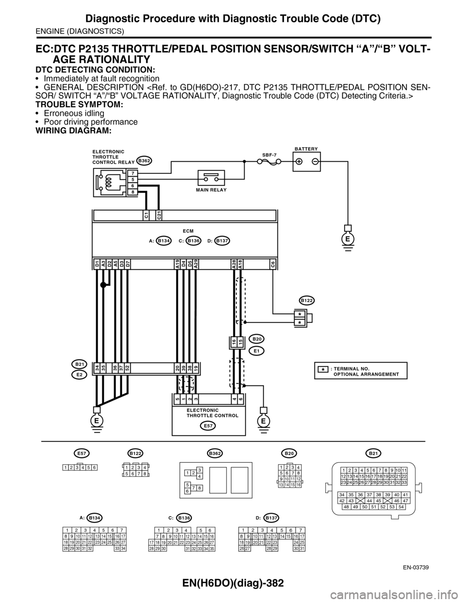
EC:DTC P2135 THROTTLE/PEDAL POSITION SENSOR/SWITCH “A”/“B” VOLT-
AGE RATIONALITY
DTC DETECTING CONDITION:
•Immediately at fault recognition
•GENERAL DESCRIPTION
TROUBLE SYMPTOM:
•Erroneous idling
•Poor driving performance
WIRING DIAGRAM:
EN-03739
SBF-7
B134A:B137B136D:
B362
E1
B20
C:E
EE
C1C21
38392019
1615
*
*
E2
B21
E57
461235
D4D5A29A19A5D3D7A3D2D1
3536375234
A28A18C6
ECM
57
86
B362
12
78
34
56
B21
12345678910 1112 1314 1516 1718 1920 21222324 25
34 35 36 37 38 39 40 41
48 49 50 51 52 53 5442 43 44 45 46 47
26 2728 2930 313233
B122
12345678
1289563410 11 121920 2129 3031
13 14 15161727281822 2324 25 267
32 3334 35
B136C:
12789563410 11 121920 2129 30 31
13 14 151617
27 281822 23 24 2526
B137D:
BATTERY
MAIN RELAY
ELECTRONICTHROTTLECONTROL RELAY
ELECTRONICTHROTTLE CONTROL
B20
1234567891011 121314 15 16
E57
123456
B122
*: TERMINAL NO. OPTIONAL ARRANGEMENT
A:B134
85610 11 12 13 14 157213416
3019 20 2228 29
91718252123 24323126 2733 34
Page 1544 of 2453
EN(H6DO)(diag)-383
Diagnostic Procedure with Diagnostic Trouble Code (DTC)
ENGINE (DIAGNOSTICS)
Step Check Yes No
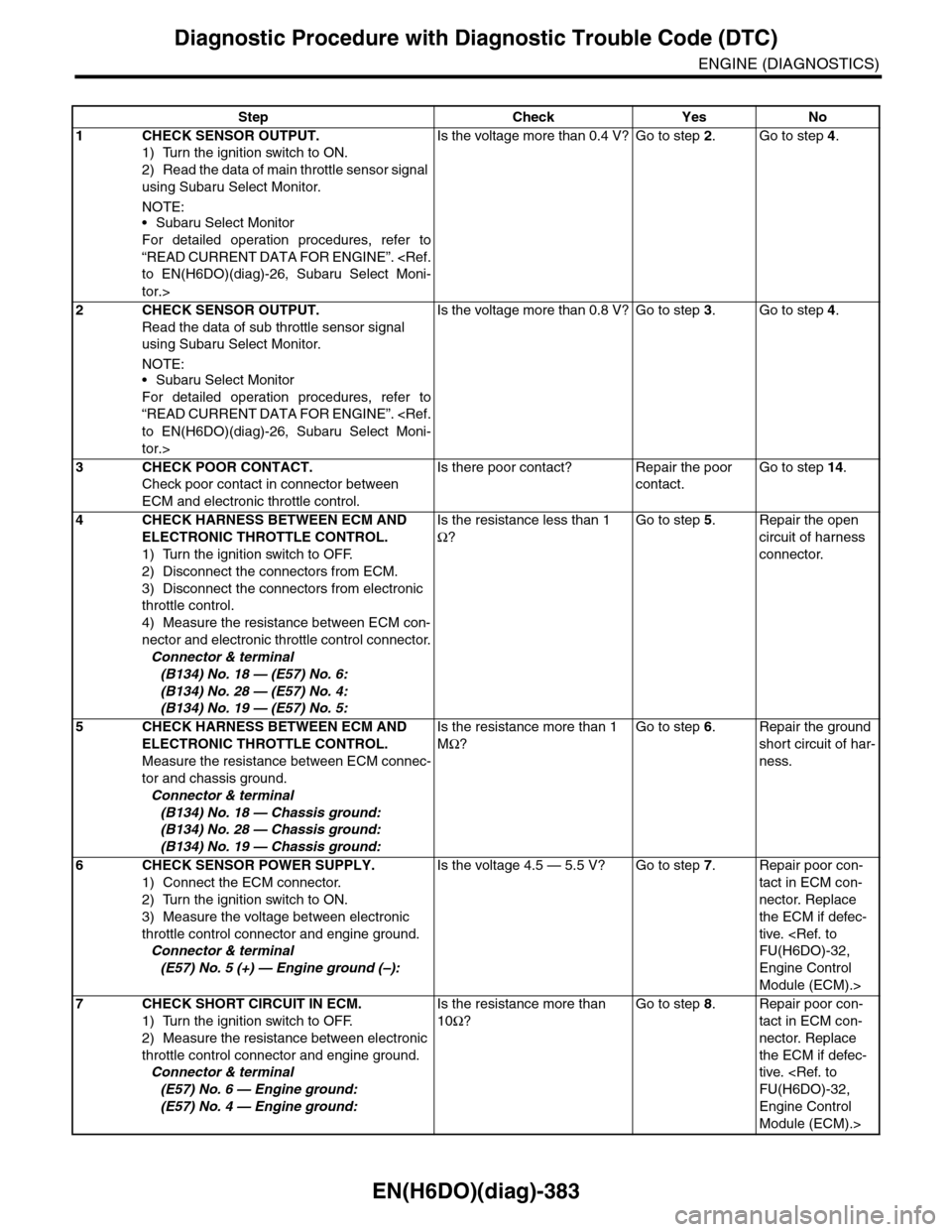
1CHECK SENSOR OUTPUT.
1) Turn the ignition switch to ON.
2) Read the data of main throttle sensor signal
using Subaru Select Monitor.
NOTE:•Subaru Select Monitor
For detailed operation procedures, refer to
“READ CURRENT DATA FOR ENGINE”.
tor.>
Is the voltage more than 0.4 V? Go to step 2.Go to step 4.
2CHECK SENSOR OUTPUT.
Read the data of sub throttle sensor signal
using Subaru Select Monitor.
NOTE:•Subaru Select Monitor
For detailed operation procedures, refer to
“READ CURRENT DATA FOR ENGINE”.
tor.>
Is the voltage more than 0.8 V? Go to step 3.Go to step 4.
3CHECK POOR CONTACT.
Check poor contact in connector between
ECM and electronic throttle control.
Is there poor contact? Repair the poor
contact.
Go to step 14.
4CHECK HARNESS BETWEEN ECM AND
ELECTRONIC THROTTLE CONTROL.
1) Turn the ignition switch to OFF.
2) Disconnect the connectors from ECM.
3) Disconnect the connectors from electronic
throttle control.
4) Measure the resistance between ECM con-
nector and electronic throttle control connector.
Connector & terminal
(B134) No. 18 — (E57) No. 6:
(B134) No. 28 — (E57) No. 4:
(B134) No. 19 — (E57) No. 5:
Is the resistance less than 1
Ω?
Go to step 5.Repair the open
circuit of harness
connector.
5CHECK HARNESS BETWEEN ECM AND
ELECTRONIC THROTTLE CONTROL.
Measure the resistance between ECM connec-
tor and chassis ground.
Connector & terminal
(B134) No. 18 — Chassis ground:
(B134) No. 28 — Chassis ground:
(B134) No. 19 — Chassis ground:
Is the resistance more than 1
MΩ?
Go to step 6.Repair the ground
short circuit of har-
ness.
6CHECK SENSOR POWER SUPPLY.
1) Connect the ECM connector.
2) Turn the ignition switch to ON.
3) Measure the voltage between electronic
throttle control connector and engine ground.
Connector & terminal
(E57) No. 5 (+) — Engine ground (–):
Is the voltage 4.5 — 5.5 V? Go to step 7.Repair poor con-
tact in ECM con-
nector. Replace
the ECM if defec-
tive.
Engine Control
Module (ECM).>
7CHECK SHORT CIRCUIT IN ECM.
1) Turn the ignition switch to OFF.
2) Measure the resistance between electronic
throttle control connector and engine ground.
Connector & terminal
(E57) No. 6 — Engine ground:
(E57) No. 4 — Engine ground:
Is the resistance more than
10Ω?
Go to step 8.Repair poor con-
tact in ECM con-
nector. Replace
the ECM if defec-
tive.
Engine Control
Module (ECM).>
Page 1545 of 2453
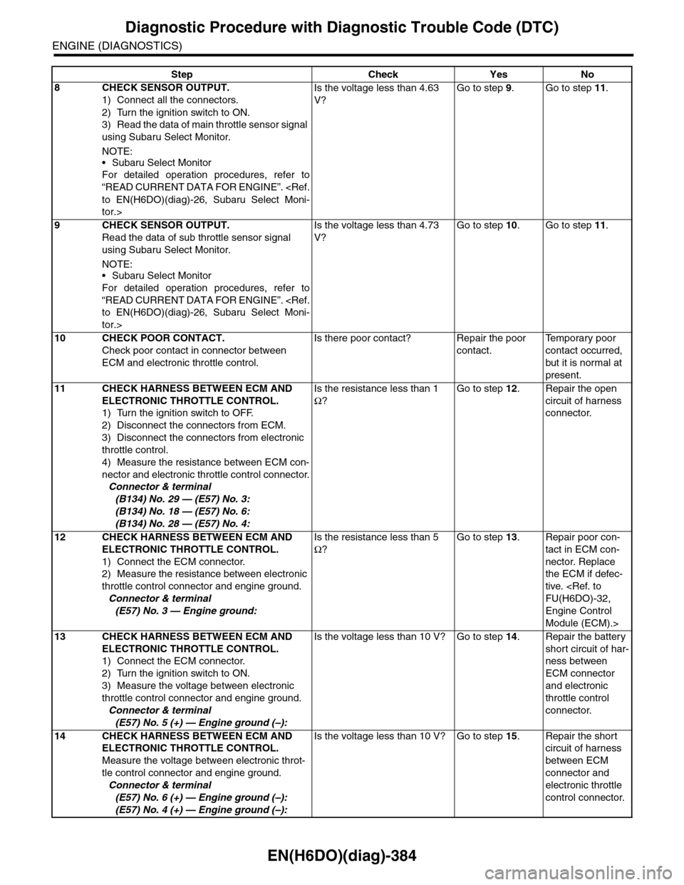
EN(H6DO)(diag)-384
Diagnostic Procedure with Diagnostic Trouble Code (DTC)
ENGINE (DIAGNOSTICS)
8CHECK SENSOR OUTPUT.
1) Connect all the connectors.
2) Turn the ignition switch to ON.
3) Read the data of main throttle sensor signal
using Subaru Select Monitor.
NOTE:
•Subaru Select Monitor
For detailed operation procedures, refer to
“READ CURRENT DATA FOR ENGINE”.
tor.>
Is the voltage less than 4.63
V?
Go to step 9.Go to step 11.
9CHECK SENSOR OUTPUT.
Read the data of sub throttle sensor signal
using Subaru Select Monitor.
NOTE:•Subaru Select Monitor
For detailed operation procedures, refer to
“READ CURRENT DATA FOR ENGINE”.
tor.>
Is the voltage less than 4.73
V?
Go to step 10.Go to step 11.
10 CHECK POOR CONTACT.
Check poor contact in connector between
ECM and electronic throttle control.
Is there poor contact? Repair the poor
contact.
Te m p o r a r y p o o r
contact occurred,
but it is normal at
present.
11 CHECK HARNESS BETWEEN ECM AND
ELECTRONIC THROTTLE CONTROL.
1) Turn the ignition switch to OFF.
2) Disconnect the connectors from ECM.
3) Disconnect the connectors from electronic
throttle control.
4) Measure the resistance between ECM con-
nector and electronic throttle control connector.
Connector & terminal
(B134) No. 29 — (E57) No. 3:
(B134) No. 18 — (E57) No. 6:
(B134) No. 28 — (E57) No. 4:
Is the resistance less than 1
Ω?
Go to step 12.Repair the open
circuit of harness
connector.
12 CHECK HARNESS BETWEEN ECM AND
ELECTRONIC THROTTLE CONTROL.
1) Connect the ECM connector.
2) Measure the resistance between electronic
throttle control connector and engine ground.
Connector & terminal
(E57) No. 3 — Engine ground:
Is the resistance less than 5
Ω?
Go to step 13.Repair poor con-
tact in ECM con-
nector. Replace
the ECM if defec-
tive.
Engine Control
Module (ECM).>
13 CHECK HARNESS BETWEEN ECM AND
ELECTRONIC THROTTLE CONTROL.
1) Connect the ECM connector.
2) Turn the ignition switch to ON.
3) Measure the voltage between electronic
throttle control connector and engine ground.
Connector & terminal
(E57) No. 5 (+) — Engine ground (–):
Is the voltage less than 10 V? Go to step 14.Repair the battery
short circuit of har-
ness between
ECM connector
and electronic
throttle control
connector.
14 CHECK HARNESS BETWEEN ECM AND
ELECTRONIC THROTTLE CONTROL.
Measure the voltage between electronic throt-
tle control connector and engine ground.
Connector & terminal
(E57) No. 6 (+) — Engine ground (–):
(E57) No. 4 (+) — Engine ground (–):
Is the voltage less than 10 V? Go to step 15.Repair the short
circuit of harness
between ECM
connector and
electronic throttle
control connector.
Step Check Yes No
Page 1546 of 2453
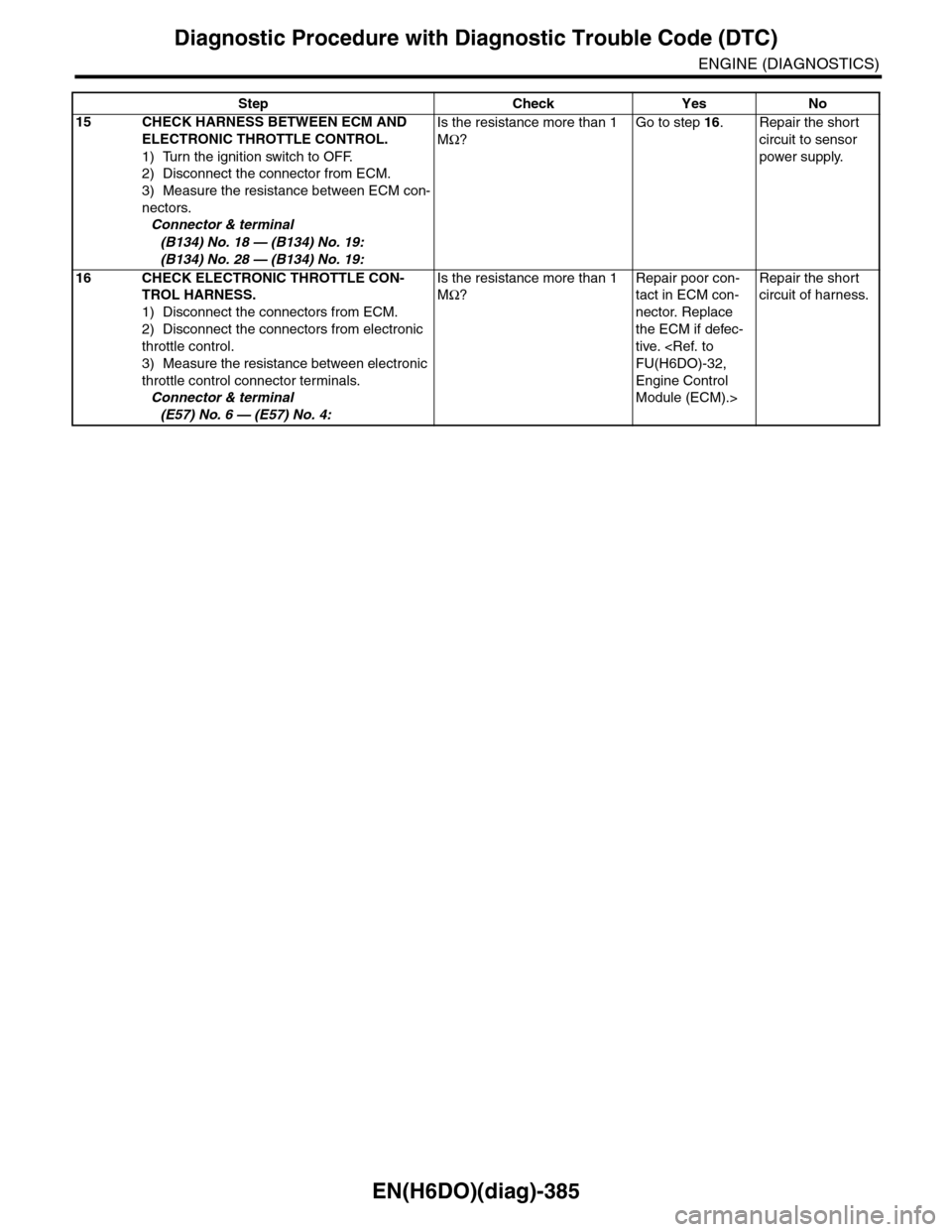
EN(H6DO)(diag)-385
Diagnostic Procedure with Diagnostic Trouble Code (DTC)
ENGINE (DIAGNOSTICS)
15 CHECK HARNESS BETWEEN ECM AND
ELECTRONIC THROTTLE CONTROL.
1) Turn the ignition switch to OFF.
2) Disconnect the connector from ECM.
3) Measure the resistance between ECM con-
nectors.
Connector & terminal
(B134) No. 18 — (B134) No. 19:
(B134) No. 28 — (B134) No. 19:
Is the resistance more than 1
MΩ?
Go to step 16.Repair the short
circuit to sensor
power supply.
16 CHECK ELECTRONIC THROTTLE CON-
TROL HARNESS.
1) Disconnect the connectors from ECM.
2) Disconnect the connectors from electronic
throttle control.
3) Measure the resistance between electronic
throttle control connector terminals.
Connector & terminal
(E57) No. 6 — (E57) No. 4:
Is the resistance more than 1
MΩ?
Repair poor con-
tact in ECM con-
nector. Replace
the ECM if defec-
tive.
Engine Control
Module (ECM).>
Repair the short
circuit of harness.
Step Check Yes No