SUBARU TRIBECA 2009 1.G Service Workshop Manual
TRIBECA 2009 1.G
SUBARU
SUBARU
https://www.carmanualsonline.info/img/17/7322/w960_7322-0.png
SUBARU TRIBECA 2009 1.G Service Workshop Manual
Page 1579 of 2453
FU(H6DO)-18
Crankshaft Position Sensor
FUEL INJECTION (FUEL SYSTEMS)
5. Crankshaft Position Sensor
A: REMOVAL
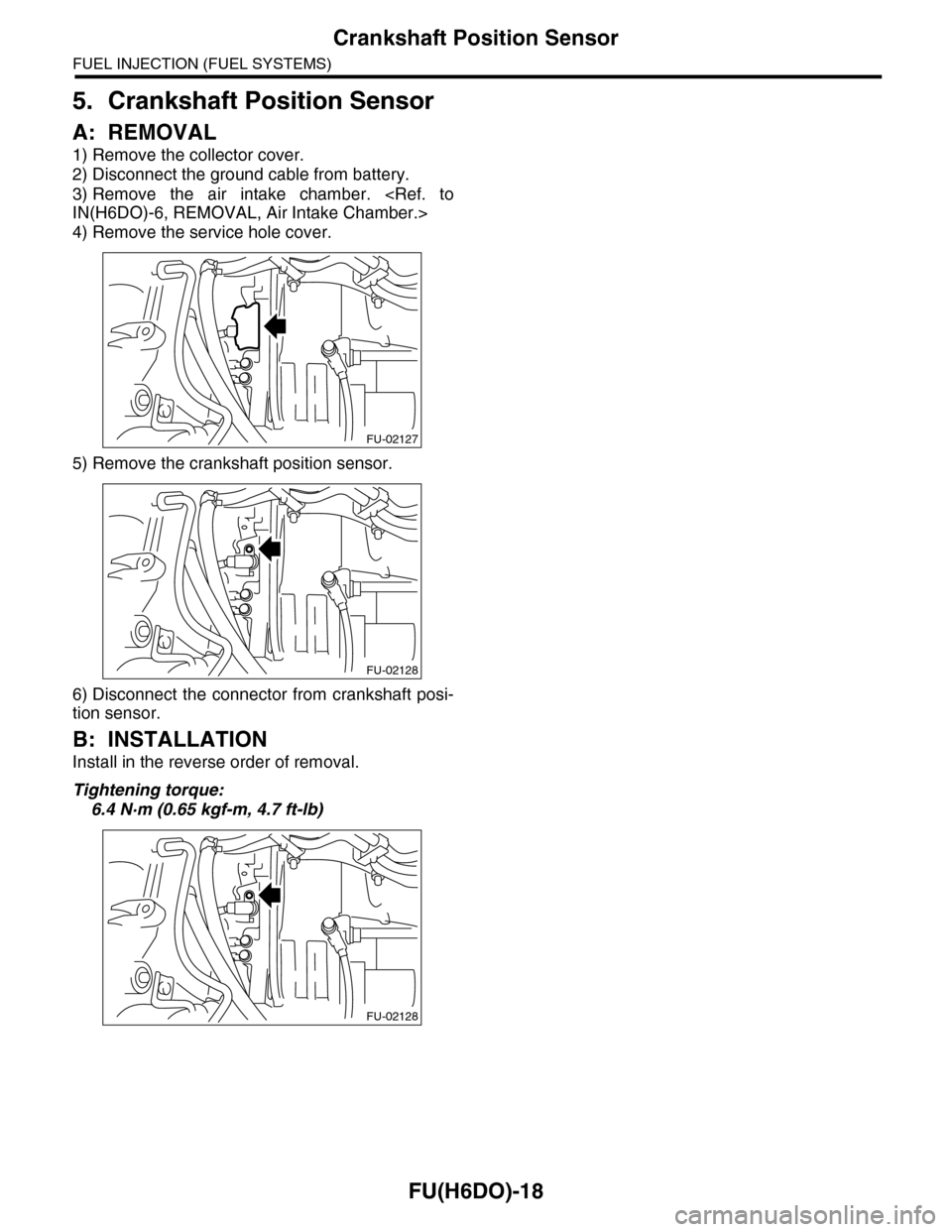
1) Remove the collector cover.
2) Disconnect the ground cable from battery.
3) Remove the air intake chamber.
IN(H6DO)-6, REMOVAL, Air Intake Chamber.>
4) Remove the service hole cover.
5) Remove the crankshaft position sensor.
6) Disconnect the connector from crankshaft posi-
tion sensor.
B: INSTALLATION
Install in the reverse order of removal.
Tightening torque:
6.4 N·m (0.65 kgf-m, 4.7 ft-lb)
FU-02127
FU-02128
FU-02128
Page 1580 of 2453
FU(H6DO)-19
Camshaft Position Sensor
FUEL INJECTION (FUEL SYSTEMS)
6. Camshaft Position Sensor
A: REMOVAL
1) Remove the collector cover.
2) Disconnect the ground cable from battery.
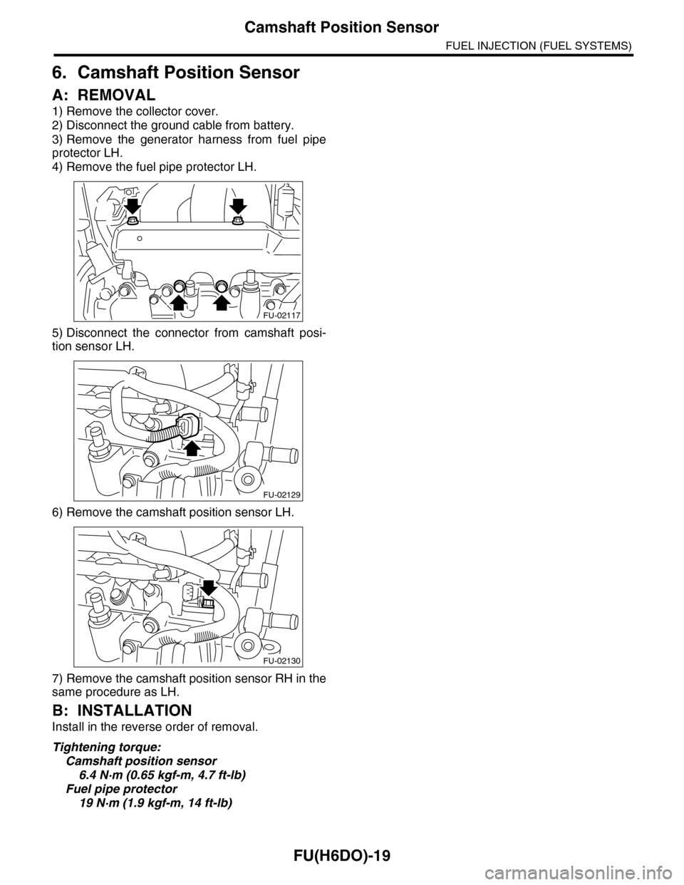
3) Remove the generator harness from fuel pipe
protector LH.
4) Remove the fuel pipe protector LH.
5) Disconnect the connector from camshaft posi-
tion sensor LH.
6) Remove the camshaft position sensor LH.
7) Remove the camshaft position sensor RH in the
same procedure as LH.
B: INSTALLATION
Install in the reverse order of removal.
Tightening torque:
Camshaft position sensor
6.4 N·m (0.65 kgf-m, 4.7 ft-lb)
Fuel pipe protector
19 N·m (1.9 kgf-m, 14 ft-lb)
FU-02117
FU-02129
FU-02130
Page 1581 of 2453
FU(H6DO)-20
Knock Sensor
FUEL INJECTION (FUEL SYSTEMS)
7. Knock Sensor
A: REMOVAL
1) Remove the collector cover.
2) Disconnect the ground cable from battery.
3) Remove the intake manifold.
fold.>
4) Disconnect the knock sensor connector.
5) Remove the knock sensor from cylinder block.
B: INSTALLATION
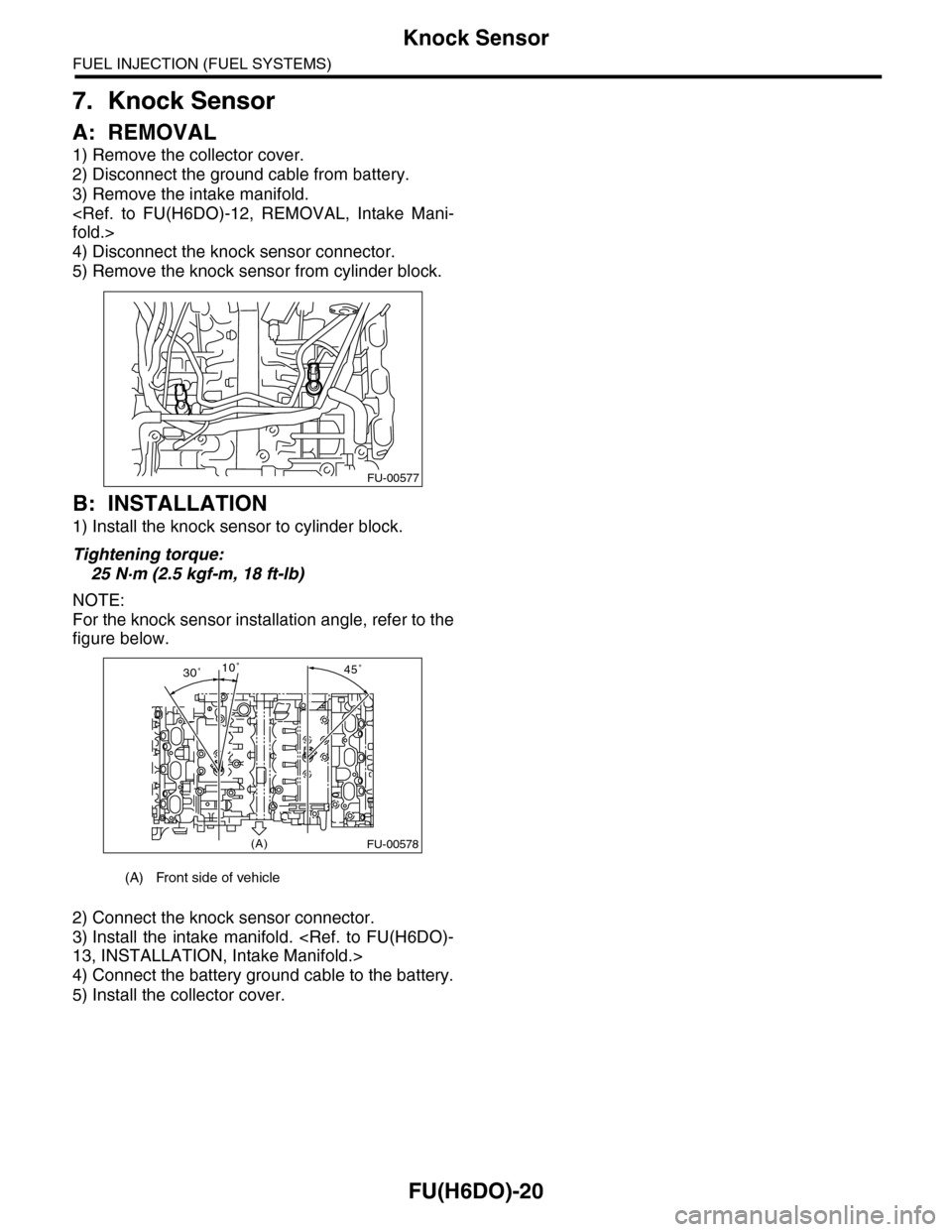
1) Install the knock sensor to cylinder block.
Tightening torque:
25 N·m (2.5 kgf-m, 18 ft-lb)
NOTE:
For the knock sensor installation angle, refer to the
figure below.
2) Connect the knock sensor connector.
3) Install the intake manifold.
13, INSTALLATION, Intake Manifold.>
4) Connect the battery ground cable to the battery.
5) Install the collector cover.
(A) Front side of vehicle
FU-00577
45˚30˚10˚
(A)FU-00578
Page 1582 of 2453
FU(H6DO)-21
Throttle Position Sensor
FUEL INJECTION (FUEL SYSTEMS)
8. Throttle Position Sensor
A: SPECIFICATION
Throttle body is a non-disassembled part, so do not
remove the throttle position sensor from throttle
body.
Refer to “Throttle Body” for removal and installation
procedure.
Throttle Body.>
LATION, Throttle Body.>
Page 1583 of 2453
FU(H6DO)-22
Manifold Absolute Pressure Sensor
FUEL INJECTION (FUEL SYSTEMS)
9. Manifold Absolute Pressure
Sensor
A: REMOVAL
1) Remove the collector cover.
2) Disconnect the ground cable from battery.
3) Disconnect the connector from manifold abso-
lute pressure sensor (A), and remove the filter as-
sembly (B) from intake manifold.
4) Remove the manifold absolute pressure sensor
from intake manifold.
B: INSTALLATION
Install in the reverse order of removal.
Tightening torque:
6.4 N·m (0.65 kgf-m, 4.7 ft-lb)
FU-02131
(B)(A)
Page 1584 of 2453
FU(H6DO)-23
Mass Air Flow and Intake Air Temperature Sensor
FUEL INJECTION (FUEL SYSTEMS)
10.Mass Air Flow and Intake Air
Temperature Sensor
A: REMOVAL
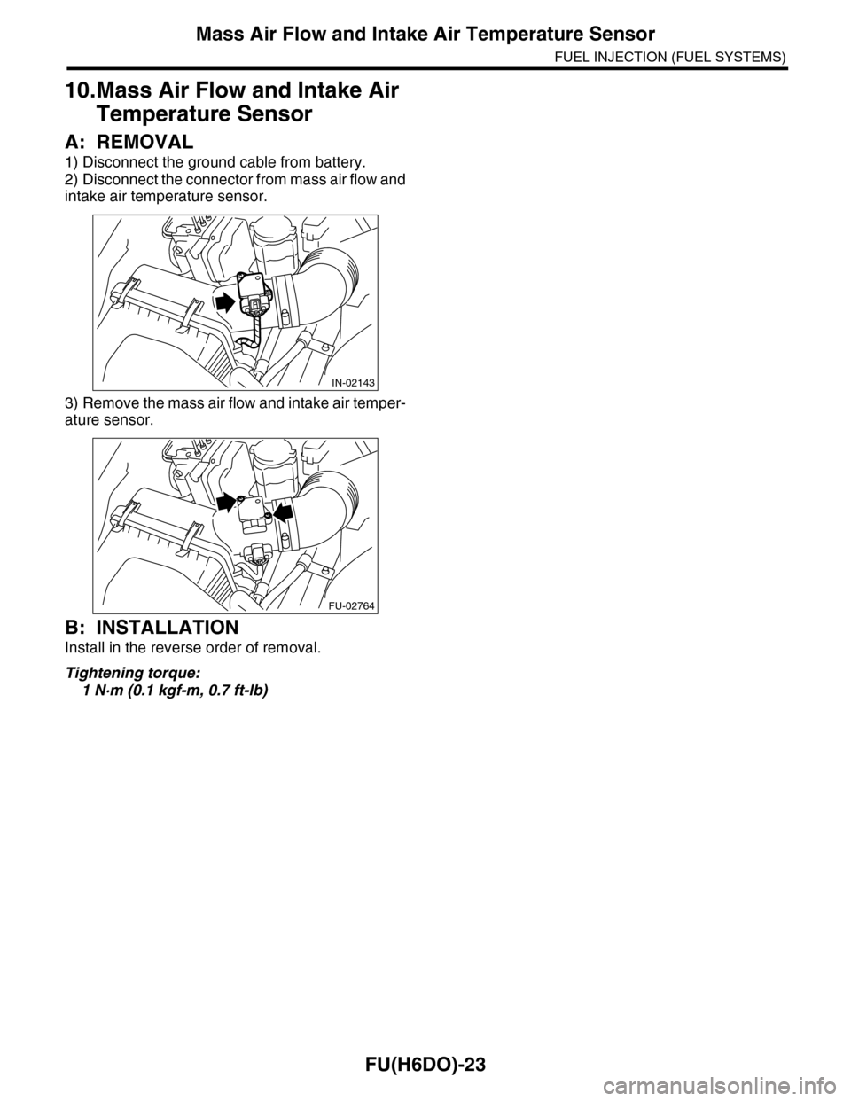
1) Disconnect the ground cable from battery.
2) Disconnect the connector from mass air flow and
intake air temperature sensor.
3) Remove the mass air flow and intake air temper-
ature sensor.
B: INSTALLATION
Install in the reverse order of removal.
Tightening torque:
1 N·m (0.1 kgf-m, 0.7 ft-lb)
IN-02143
FU-02764
Page 1588 of 2453
FU(H6DO)-27
Oil Temperature Sensor
FUEL INJECTION (FUEL SYSTEMS)
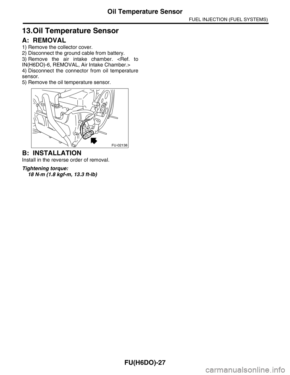
13.Oil Temperature Sensor
A: REMOVAL
1) Remove the collector cover.
2) Disconnect the ground cable from battery.
3) Remove the air intake chamber.
IN(H6DO)-6, REMOVAL, Air Intake Chamber.>
4) Disconnect the connector from oil temperature
sensor.
5) Remove the oil temperature sensor.
B: INSTALLATION
Install in the reverse order of removal.
Tightening torque:
18 N·m (1.8 kgf-m, 13.3 ft-lb)
FU-02138
Page 1589 of 2453
FU(H6DO)-28
Front Oxygen (A/F) Sensor
FUEL INJECTION (FUEL SYSTEMS)
14.Front Oxygen (A/F) Sensor
A: REMOVAL
1) Set the vehicle on a lift.
2) Disconnect the ground cable from battery.
3) Lift-up the vehicle.
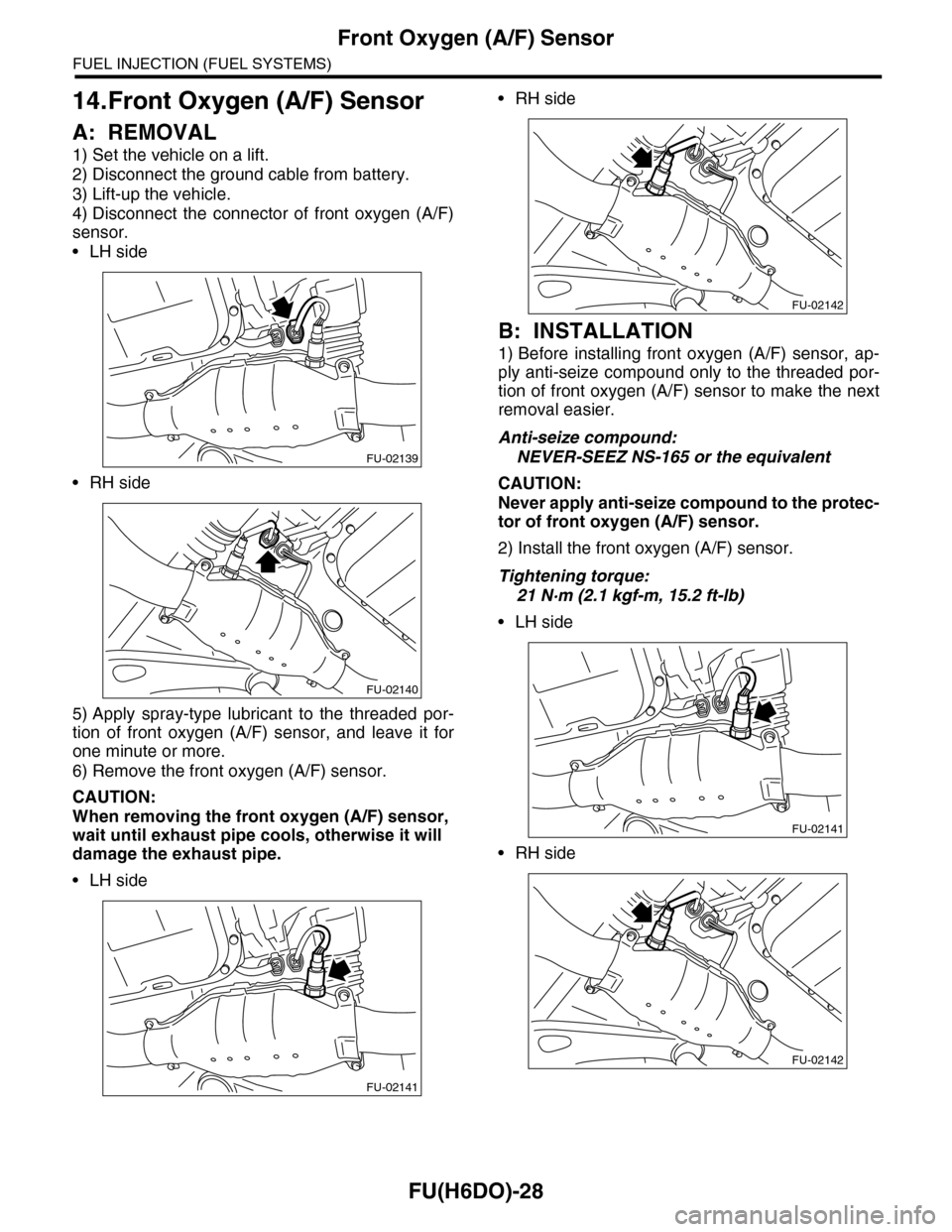
4) Disconnect the connector of front oxygen (A/F)
sensor.
•LH side
•RH side
5) Apply spray-type lubricant to the threaded por-
tion of front oxygen (A/F) sensor, and leave it for
one minute or more.
6) Remove the front oxygen (A/F) sensor.
CAUTION:
When removing the front oxygen (A/F) sensor,
wait until exhaust pipe cools, otherwise it will
damage the exhaust pipe.
•LH side
•RH side
B: INSTALLATION
1) Before installing front oxygen (A/F) sensor, ap-
ply anti-seize compound only to the threaded por-
tion of front oxygen (A/F) sensor to make the next
removal easier.
Anti-seize compound:
NEVER-SEEZ NS-165 or the equivalent
CAUTION:
Never apply anti-seize compound to the protec-
tor of front oxygen (A/F) sensor.
2) Install the front oxygen (A/F) sensor.
Tightening torque:
21 N·m (2.1 kgf-m, 15.2 ft-lb)
•LH side
•RH side
FU-02139
FU-02140
FU-02141
FU-02142
FU-02141
FU-02142
Page 1590 of 2453
FU(H6DO)-29
Front Oxygen (A/F) Sensor
FUEL INJECTION (FUEL SYSTEMS)
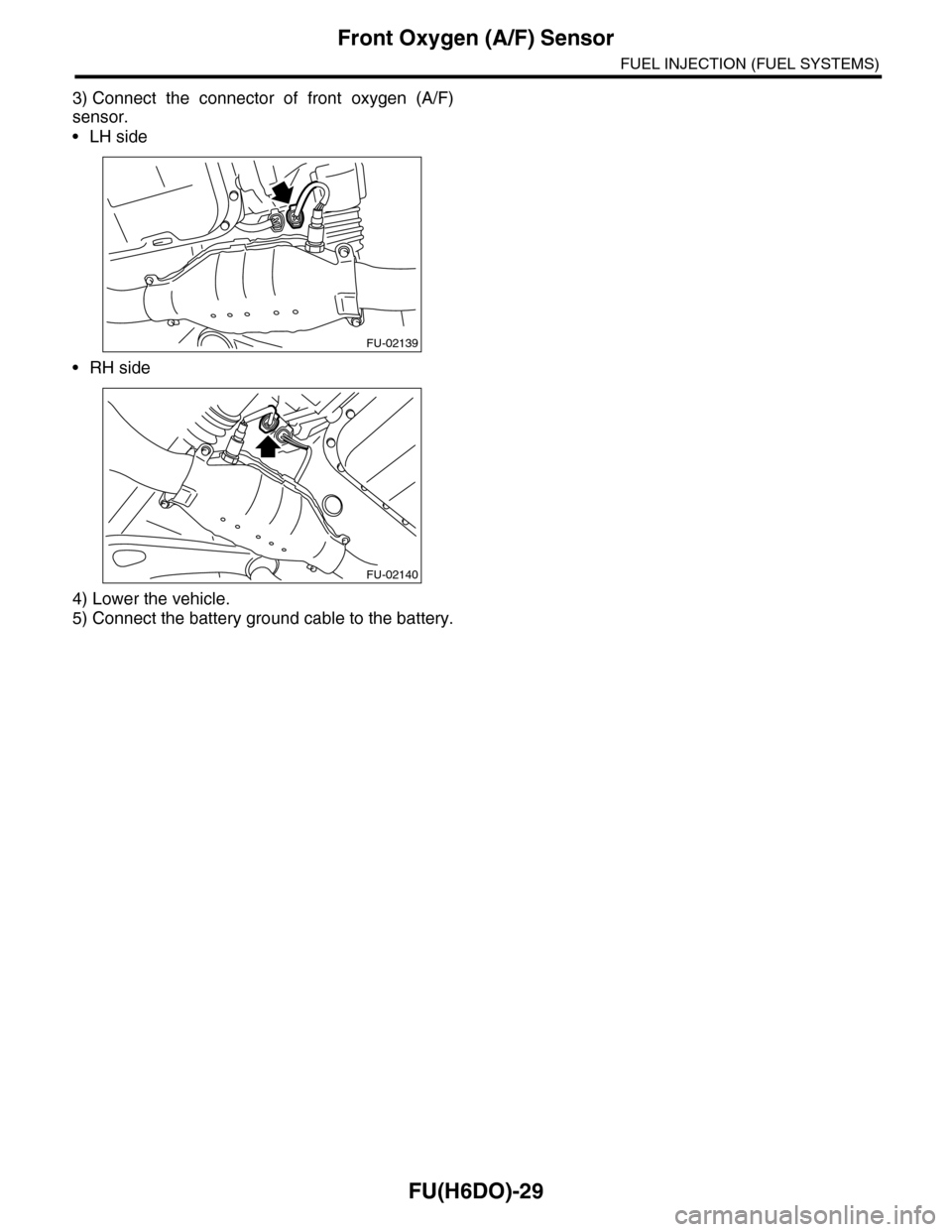
3) Connect the connector of front oxygen (A/F)
sensor.
•LH side
•RH side
4) Lower the vehicle.
5) Connect the battery ground cable to the battery.
FU-02139
FU-02140
Page 1591 of 2453
FU(H6DO)-30
Rear Oxygen Sensor
FUEL INJECTION (FUEL SYSTEMS)
15.Rear Oxygen Sensor
A: REMOVAL
1) Set the vehicle on a lift.
2) Disconnect the ground cable from battery.
3) Lift-up the vehicle.
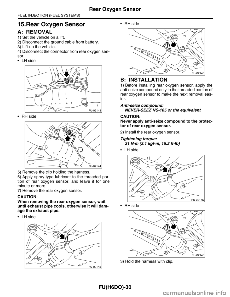
4) Disconnect the connector from rear oxygen sen-
sor.
•LH side
•RH side
5) Remove the clip holding the harness.
6) Apply spray-type lubricant to the threaded por-
tion of rear oxygen sensor, and leave it for one
minute or more.
7) Remove the rear oxygen sensor.
CAUTION:
When removing the rear oxygen sensor, wait
until exhaust pipe cools, otherwise it will dam-
age the exhaust pipe.
•LH side
•RH side
B: INSTALLATION
1) Before installing rear oxygen sensor, apply the
anti-seize compound only to the threaded portion of
rear oxygen sensor to make the next removal eas-
ier.
Anti-seize compound:
NEVER-SEEZ NS-165 or the equivalent
CAUTION:
Never apply anti-seize compound to the protec-
tor of rear oxygen sensor.
2) Install the rear oxygen sensor.
Tightening torque:
21 N·m (2.1 kgf-m, 15.2 ft-lb)
•LH side
•RH side
3) Hold the harness with clip.
FU-02143
FU-02144
FU-02145
FU-02146
FU-02145
FU-02146
