sensor SUBARU TRIBECA 2009 1.G Service Workshop Manual
[x] Cancel search | Manufacturer: SUBARU, Model Year: 2009, Model line: TRIBECA, Model: SUBARU TRIBECA 2009 1.GPages: 2453, PDF Size: 46.32 MB
Page 1789 of 2453
GD(H6DO)-177
Diagnostic Trouble Code (DTC) Detecting Criteria
GENERAL DESCRIPTION
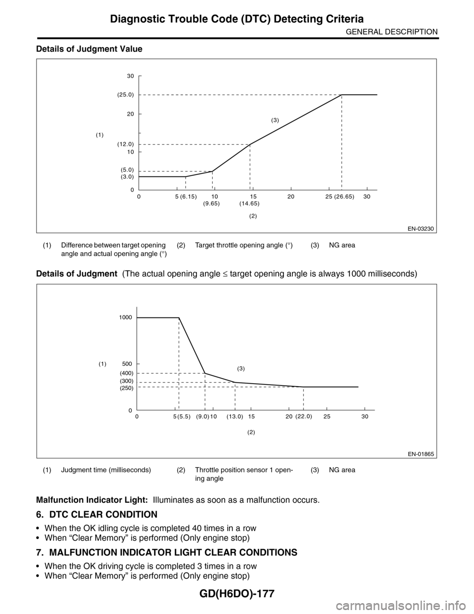
Details of Judgment Value
Details of Judgment (The actual opening angle ≤ target opening angle is always 1000 milliseconds)
Malfunction Indicator Light: Illuminates as soon as a malfunction occurs.
6. DTC CLEAR CONDITION
•When the OK idling cycle is completed 40 times in a row
•When “Clear Memory” is performed (Only engine stop)
7. MALFUNCTION INDICATOR LIGHT CLEAR CONDITIONS
•When the OK driving cycle is completed 3 times in a row
•When “Clear Memory” is performed (Only engine stop)
(1) Difference between target opening
angle and actual opening angle (°)
(2) Target throttle opening angle (°) (3) NG area
(1) Judgment time (milliseconds) (2) Throttle position sensor 1 open-
ing angle
(3) NG area
EN-03230
30
20
10
0
(25.0)
(12.0)
(5.0)(3.0)
05(6.15)10(9.65)(14.65)15 20 25 (26.65) 30
(1)
(3)
(2)
EN-01865
05(5.5)10(9.0)(13.0) 15 20 25 30
(2)
0
1000
(250)
(22.0)
(300)
(400)
500(3)(1)
Page 1794 of 2453
GD(H6DO)-182
Diagnostic Trouble Code (DTC) Detecting Criteria
GENERAL DESCRIPTION
DF:DTC P1152 O2 SENSOR CIRCUIT RANGE/PERFORMANCE (LOW) (BANK 1
SENSOR 1)
1. OUTLINE OF DIAGNOSIS
Detect that λ value remains low.
Judge as NG when lambda value is abnormal in accordance with λ value of front oxygen (A/F) sensor and
running conditions such as vehicle speed, amount of intake air engine coolant temperature, sub feedback
control, etc.
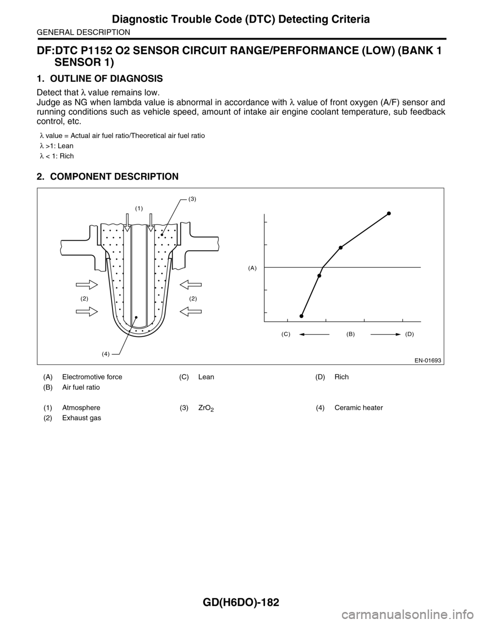
2. COMPONENT DESCRIPTION
λ value = Actual air fuel ratio/Theoretical air fuel ratio
λ >1: Lean
λ < 1: Rich
(A) Electromotive force (C) Lean (D) Rich
(B) Air fuel ratio
(1) Atmosphere (3) ZrO2(4) Ceramic heater
(2) Exhaust gas
(1)
(2)
(4)
(2)
(3)
EN-01693
(C) (B) (D)
(A)
Page 1795 of 2453
GD(H6DO)-183
Diagnostic Trouble Code (DTC) Detecting Criteria
GENERAL DESCRIPTION
3. ENABLE CONDITIONS
4. GENERAL DRIVING CYCLE
Perform diagnosis continuously at a constant speed of 20 km/h (12 MPH) or more, starting from 60 seconds
after starting the engine.
5. DIAGNOSTIC METHOD
Judge as NG when the continuous time of meeting the malfunction criteria below becomes more than the
time needed for diagnosis (10 seconds). Judge as OK and clear the NG when the malfunction criteria below
are not met.
Time Needed for Diagnosis: 10 seconds
Malfunction Indicator Light Illumination: Illuminates when malfunctions occur in 2 continuous driving cy-
cles.
6. DTC CLEAR CONDITION
•When the OK idling cycle is completed 40 times in a row
•When “Clear Memory” is performed
7. MALFUNCTION INDICATOR LIGHT CLEAR CONDITIONS
•When the OK driving cycle is completed 3 times in a row
•When “Clear Memory” is performed
8. FAIL SAFE
•Front oxygen (A/F) sensor main learning compensation: Not allowed to calculate.
•Rear oxygen sensor sub learning compensation: Not allowed to calculate.
•Purge control: Not allowed to purge
9. ECM OPERATION AT DTC SETTING
Memorize the freeze frame data. (For test mode $02)
Secondary Parameters Enable Conditions
All secondary parameters enable conditions4 seconds or more
Battery voltage > 10.9 V
Atmospheric pressure > 75.1 kPa (563 mmHg, 22.2 inHg)
Rear oxygen sensor sub feedback Execution
Rear oxygen sensor output voltage –
Feedback target voltage
–0.2 V ←→ 0.1 V
or rear oxygen sensor sub feedback
compensation coefficient
On Min.
or rear oxygen sensor sub feedback
compensation coefficient
On Max.
After engine starting 60 seconds or more
Engine coolant temperature≥ 75°C (167°F)
Ve h i c l e s p e e d≥ 20 km/h (12 MPH)
Amount of intake air≥ 8 g (0.28 oz)/s
Load change in 1/3 engine revolution.≤ 0.02g (0.001 oz)/rev
Fr o nt ox yg e n ( A / F) s en so r im pe d an c e 0 ←→ 50 Ω
Learning value of evaporation gas density≤ 0.12
To t a l t i m e o f o p e r a t i n g c a n i s t e r p u r g e 2 0 s e c o n d s o r m o r e
Ta r g e t e d l a m b d a v a l u e l o a d c o m p e n s a -
tion coefficient
–0.05 ←→ 0.05
Judgment Value
Malfunction Criteria Threshold Value
Output λ value when rear oxygen sensor
sub feedback compensation coefficient
is not at maximum limit
≤ 0.85
Page 1796 of 2453
GD(H6DO)-184
Diagnostic Trouble Code (DTC) Detecting Criteria
GENERAL DESCRIPTION
DG:DTC P1153 O2 SENSOR CIRCUIT RANGE/PERFORMANCE (HIGH) (BANK 1
SENSOR 1)
1. OUTLINE OF DIAGNOSIS
Detect that λ value remains high.
Judge as NG when lambda value is abnormal in accordance with λ value of front oxygen (A/F) sensor and
running conditions such as vehicle speed, amount of intake air engine coolant temperature, sub feedback
control, etc.
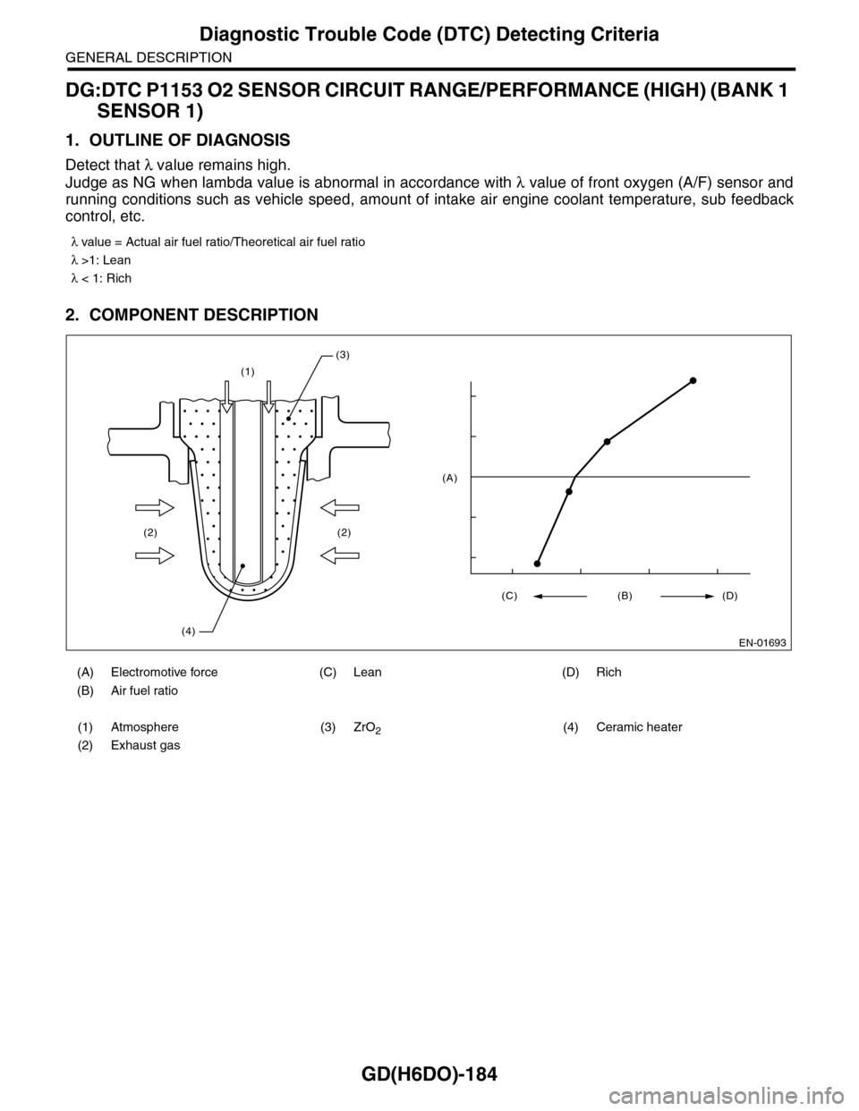
2. COMPONENT DESCRIPTION
λ value = Actual air fuel ratio/Theoretical air fuel ratio
λ >1: Lean
λ < 1: Rich
(A) Electromotive force (C) Lean (D) Rich
(B) Air fuel ratio
(1) Atmosphere (3) ZrO2(4) Ceramic heater
(2) Exhaust gas
(1)
(2)
(4)
(2)
(3)
EN-01693
(C) (B) (D)
(A)
Page 1797 of 2453
GD(H6DO)-185
Diagnostic Trouble Code (DTC) Detecting Criteria
GENERAL DESCRIPTION
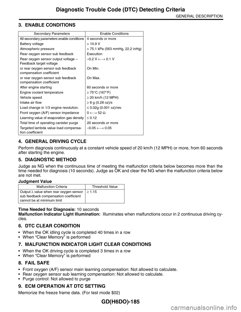
3. ENABLE CONDITIONS
4. GENERAL DRIVING CYCLE
Perform diagnosis continuously at a constant vehicle speed of 20 km/h (12 MPH) or more, from 60 seconds
after starting the engine.
5. DIAGNOSTIC METHOD
Judge as NG when the continuous time of meeting the malfunction criteria below becomes more than the
time needed for diagnosis (10 seconds). Judge as OK and clear the NG when the malfunction criteria below
are not met.
Time Needed for Diagnosis: 10 seconds
Malfunction Indicator Light Illumination: Illuminates when malfunctions occur in 2 continuous driving cy-
cles.
6. DTC CLEAR CONDITION
•When the OK idling cycle is completed 40 times in a row
•When “Clear Memory” is performed
7. MALFUNCTION INDICATOR LIGHT CLEAR CONDITIONS
•When the OK driving cycle is completed 3 times in a row
•When “Clear Memory” is performed
8. FAIL SAFE
•Front oxygen (A/F) sensor main learning compensation: Not allowed to calculate.
•Rear oxygen sensor sub learning compensation: Not allowed to calculate.
•Purge control: Not allowed to purge
9. ECM OPERATION AT DTC SETTING
Memorize the freeze frame data. (For test mode $02)
Secondary Parameters Enable Conditions
All secondary parameters enable conditions4 seconds or more
Battery voltage > 10.9 V
Atmospheric pressure > 75.1 kPa (563 mmHg, 22.2 inHg)
Rear oxygen sensor sub feedback Execution
Rear oxygen sensor output voltage –
Feedback target voltage
–0.2 V ←→ 0.1 V
or rear oxygen sensor sub feedback
compensation coefficient
On Min.
or rear oxygen sensor sub feedback
compensation coefficient
On Max.
After engine starting 60 seconds or more
Engine coolant temperature≥ 75°C (167°F)
Ve h i c l e s p e e d≥ 20 km/h (12 MPH)
Intake air flow≥ 8 g (0.28 oz)/s
Load change in 1/3 engine revolution.≤ 0.02g (0.001 oz)/rev
Fr o nt ox yg e n ( A / F) s en so r im pe d an c e 0 ←→ 52 Ω
Learning value of evaporation gas density≤ 0.12
To t a l t i m e o f o p e r a t i n g c a n i s t e r p u r g e 2 0 s e c o n d s o r m o r e
Ta r g e t e d l a m b d a v a l u e l o a d c o m p e n s a -
tion coefficient
–0.05 ←→ 0.05
Judgment Value
Malfunction Criteria Threshold Value
Output λ value when rear oxygen sensor
sub feedback compensation coefficient
cannot be at minimum limit
≥ 1.15
Page 1798 of 2453
GD(H6DO)-186
Diagnostic Trouble Code (DTC) Detecting Criteria
GENERAL DESCRIPTION
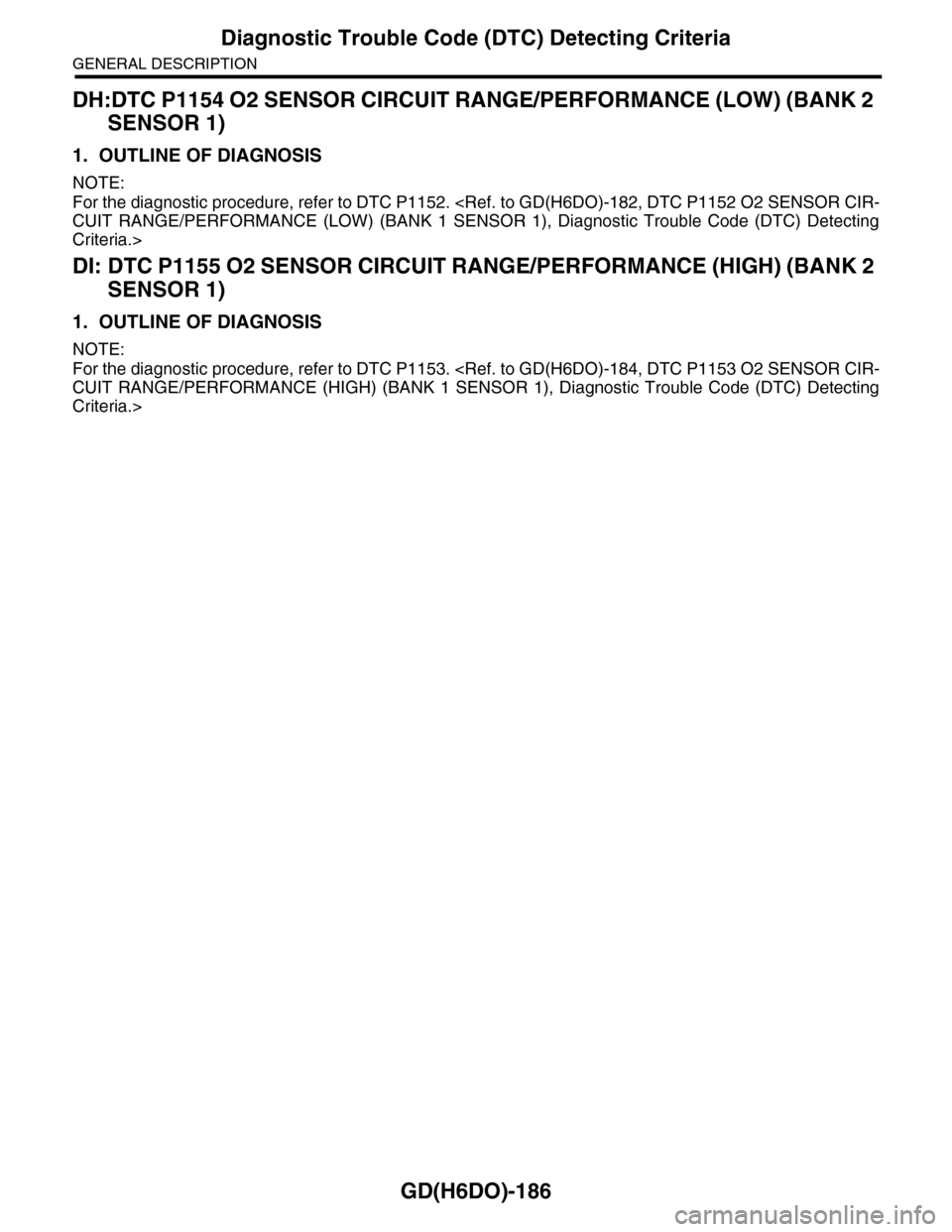
DH:DTC P1154 O2 SENSOR CIRCUIT RANGE/PERFORMANCE (LOW) (BANK 2
SENSOR 1)
1. OUTLINE OF DIAGNOSIS
NOTE:
For the diagnostic procedure, refer to DTC P1152.
Criteria.>
DI: DTC P1155 O2 SENSOR CIRCUIT RANGE/PERFORMANCE (HIGH) (BANK 2
SENSOR 1)
1. OUTLINE OF DIAGNOSIS
NOTE:
For the diagnostic procedure, refer to DTC P1153.
Criteria.>
Page 1799 of 2453
GD(H6DO)-187
Diagnostic Trouble Code (DTC) Detecting Criteria
GENERAL DESCRIPTION
DJ:DTC P1160 RETURN SPRING FAILURE
1. OUTLINE OF DIAGNOSIS
Judge as NG when the valve is opened more than the default opening angle, but does not move to the close
direction with the motor power stopped.
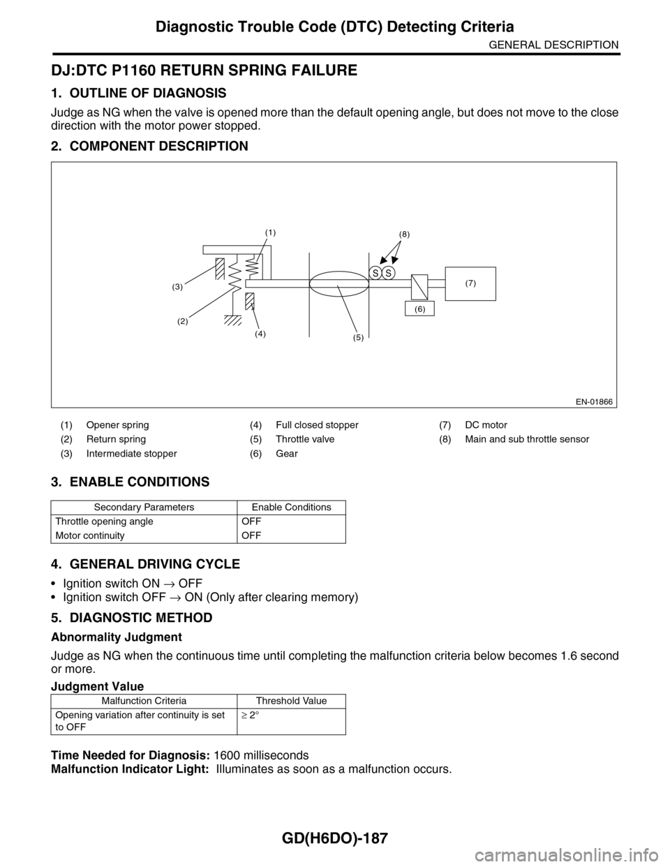
2. COMPONENT DESCRIPTION
3. ENABLE CONDITIONS
4. GENERAL DRIVING CYCLE
•Ignition switch ON → OFF
•Ignition switch OFF → ON (Only after clearing memory)
5. DIAGNOSTIC METHOD
Abnormality Judgment
Judge as NG when the continuous time until completing the malfunction criteria below becomes 1.6 second
or more.
Time Needed for Diagnosis: 1600 milliseconds
Malfunction Indicator Light: Illuminates as soon as a malfunction occurs.
(1) Opener spring (4) Full closed stopper (7) DC motor
(2) Return spring (5) Throttle valve (8) Main and sub throttle sensor
(3) Intermediate stopper (6) Gear
Secondary Parameters Enable Conditions
Throttle opening angle OFF
Motor continuity OFF
Judgment Value
Malfunction Criteria Threshold Value
Opening variation after continuity is set
to OFF
≥ 2°
EN-01866
SS
(8)
(6)
(7)
(5)
(1)
(3)
(2)
(4)
Page 1819 of 2453
GD(H6DO)-207
Diagnostic Trouble Code (DTC) Detecting Criteria
GENERAL DESCRIPTION
EF:DTC P2109 THROTTLE/PEDAL POSITION SENSOR A MINIMUM STOP PER-
FORMANCE
1. OUTLINE OF DIAGNOSIS
Judge as NG when fully close point learning cannot conducted or abnormal value is detected.
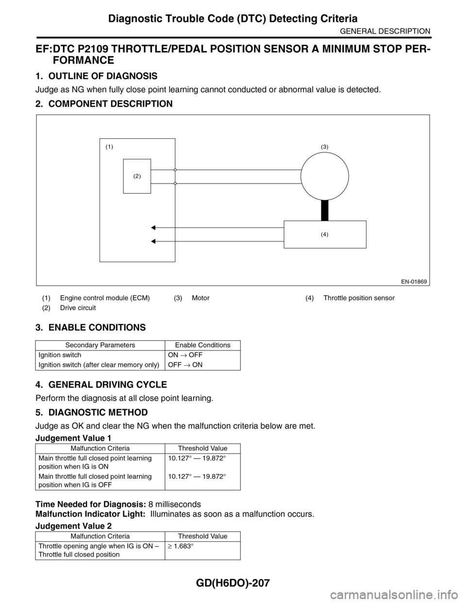
2. COMPONENT DESCRIPTION
3. ENABLE CONDITIONS
4. GENERAL DRIVING CYCLE
Perform the diagnosis at all close point learning.
5. DIAGNOSTIC METHOD
Judge as OK and clear the NG when the malfunction criteria below are met.
Time Needed for Diagnosis: 8 milliseconds
Malfunction Indicator Light: Illuminates as soon as a malfunction occurs.
(1) Engine control module (ECM) (3) Motor (4) Throttle position sensor
(2) Drive circuit
Secondary Parameters Enable Conditions
Ignition switch ON → OFF
Ignition switch (after clear memory only) OFF → ON
Judgement Value 1
Malfunction Criteria Threshold Value
Main throttle full closed point learning
position when IG is ON
10.127° — 19.872°
Main throttle full closed point learning
position when IG is OFF
10.127° — 19.872°
Judgement Value 2
Malfunction Criteria Threshold Value
Throttle opening angle when IG is ON –
Throttle full closed position
≥ 1.683°
EN-01869
(1)
(2)
(3)
(4)
Page 1821 of 2453
GD(H6DO)-209
Diagnostic Trouble Code (DTC) Detecting Criteria
GENERAL DESCRIPTION
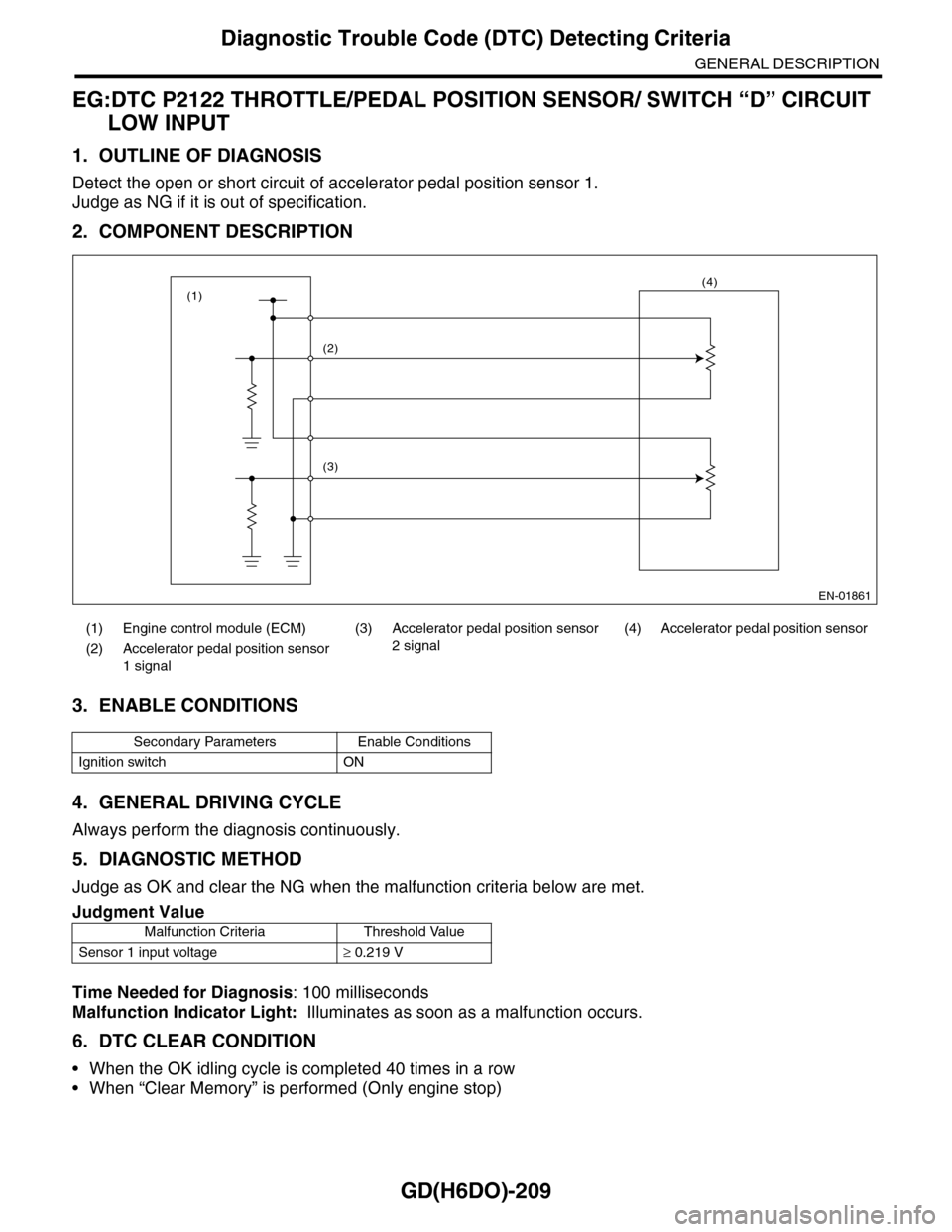
EG:DTC P2122 THROTTLE/PEDAL POSITION SENSOR/ SWITCH “D” CIRCUIT
LOW INPUT
1. OUTLINE OF DIAGNOSIS
Detect the open or short circuit of accelerator pedal position sensor 1.
Judge as NG if it is out of specification.
2. COMPONENT DESCRIPTION
3. ENABLE CONDITIONS
4. GENERAL DRIVING CYCLE
Always perform the diagnosis continuously.
5. DIAGNOSTIC METHOD
Judge as OK and clear the NG when the malfunction criteria below are met.
Time Needed for Diagnosis: 100 milliseconds
Malfunction Indicator Light: Illuminates as soon as a malfunction occurs.
6. DTC CLEAR CONDITION
•When the OK idling cycle is completed 40 times in a row
•When “Clear Memory” is performed (Only engine stop)
(1) Engine control module (ECM) (3) Accelerator pedal position sensor
2 signal
(4) Accelerator pedal position sensor
(2) Accelerator pedal position sensor
1 signal
Secondary Parameters Enable Conditions
Ignition switch ON
Judgment Value
Malfunction Criteria Threshold Value
Sensor 1 input voltage≥ 0.219 V
EN-01861
(2)
(3)
(4)(1)
Page 1822 of 2453
GD(H6DO)-210
Diagnostic Trouble Code (DTC) Detecting Criteria
GENERAL DESCRIPTION
7. MALFUNCTION INDICATOR LIGHT CLEAR CONDITIONS
•When the OK driving cycle is completed 3 times in a row
•When “Clear Memory” is performed (Only engine stop)
8. FAIL SAFE
•Single malfunction: Control with normal sensor
•Simultaneous failure: Throttle opening is fixed to 6.375°.
9. ECM OPERATION AT DTC SETTING
Memorize the freeze frame data. (For test mode $02)