sensor SUBARU TRIBECA 2009 1.G Service Workshop Manual
[x] Cancel search | Manufacturer: SUBARU, Model Year: 2009, Model line: TRIBECA, Model: SUBARU TRIBECA 2009 1.GPages: 2453, PDF Size: 46.32 MB
Page 1823 of 2453
GD(H6DO)-211
Diagnostic Trouble Code (DTC) Detecting Criteria
GENERAL DESCRIPTION
EH:DTC P2123 THROTTLE/PEDAL POSITION SENSOR/ SWITCH “D” CIRCUIT
HIGH INPUT
1. OUTLINE OF DIAGNOSIS
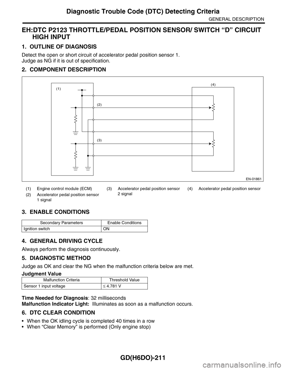
Detect the open or short circuit of accelerator pedal position sensor 1.
Judge as NG if it is out of specification.
2. COMPONENT DESCRIPTION
3. ENABLE CONDITIONS
4. GENERAL DRIVING CYCLE
Always perform the diagnosis continuously.
5. DIAGNOSTIC METHOD
Judge as OK and clear the NG when the malfunction criteria below are met.
Time Needed for Diagnosis: 32 milliseconds
Malfunction Indicator Light: Illuminates as soon as a malfunction occurs.
6. DTC CLEAR CONDITION
•When the OK idling cycle is completed 40 times in a row
•When “Clear Memory” is performed (Only engine stop)
(1) Engine control module (ECM) (3) Accelerator pedal position sensor
2 signal
(4) Accelerator pedal position sensor
(2) Accelerator pedal position sensor
1 signal
Secondary Parameters Enable Conditions
Ignition switch ON
Judgment Value
Malfunction Criteria Threshold Value
Sensor 1 input voltage≤ 4.781 V
EN-01861
(2)
(3)
(4)(1)
Page 1824 of 2453
GD(H6DO)-212
Diagnostic Trouble Code (DTC) Detecting Criteria
GENERAL DESCRIPTION
7. MALFUNCTION INDICATOR LIGHT CLEAR CONDITIONS
•When the OK driving cycle is completed 3 times in a row
•When “Clear Memory” is performed (Only engine stop)
8. FAIL SAFE
•Single malfunction: Control with normal sensor
•Simultaneous failure: Throttle opening is fixed to 6.375°.
9. ECM OPERATION AT DTC SETTING
Memorize the freeze frame data. (For test mode $02)
Page 1825 of 2453
GD(H6DO)-213
Diagnostic Trouble Code (DTC) Detecting Criteria
GENERAL DESCRIPTION
EI: DTC P2127 THROTTLE/PEDAL POSITION SENSOR/ SWITCH “E” CIRCUIT
LOW INPUT
1. OUTLINE OF DIAGNOSIS
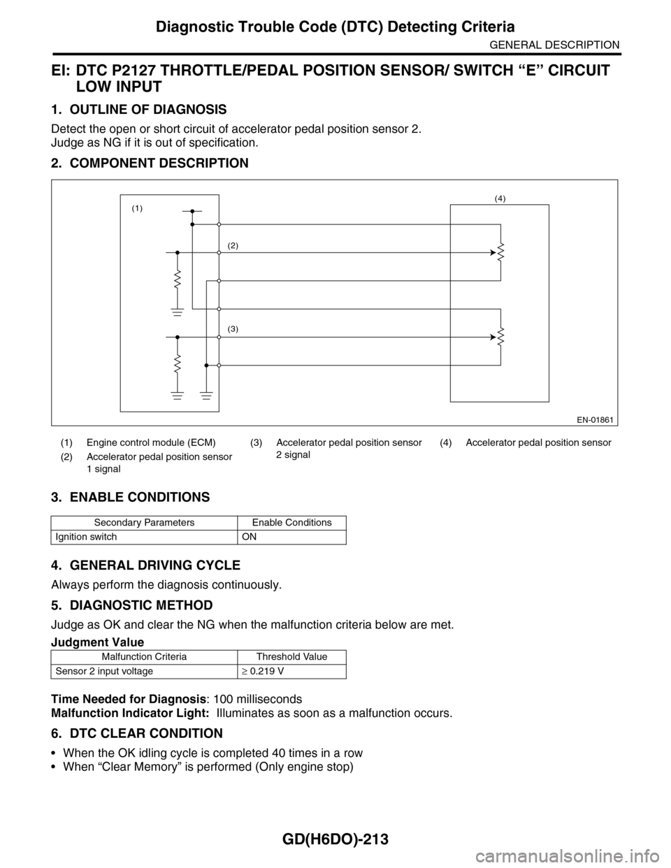
Detect the open or short circuit of accelerator pedal position sensor 2.
Judge as NG if it is out of specification.
2. COMPONENT DESCRIPTION
3. ENABLE CONDITIONS
4. GENERAL DRIVING CYCLE
Always perform the diagnosis continuously.
5. DIAGNOSTIC METHOD
Judge as OK and clear the NG when the malfunction criteria below are met.
Time Needed for Diagnosis: 100 milliseconds
Malfunction Indicator Light: Illuminates as soon as a malfunction occurs.
6. DTC CLEAR CONDITION
•When the OK idling cycle is completed 40 times in a row
•When “Clear Memory” is performed (Only engine stop)
(1) Engine control module (ECM) (3) Accelerator pedal position sensor
2 signal
(4) Accelerator pedal position sensor
(2) Accelerator pedal position sensor
1 signal
Secondary Parameters Enable Conditions
Ignition switch ON
Judgment Value
Malfunction Criteria Threshold Value
Sensor 2 input voltage≥ 0.219 V
EN-01861
(2)
(3)
(4)(1)
Page 1826 of 2453
GD(H6DO)-214
Diagnostic Trouble Code (DTC) Detecting Criteria
GENERAL DESCRIPTION
7. MALFUNCTION INDICATOR LIGHT CLEAR CONDITIONS
•When the OK driving cycle is completed 3 times in a row
•When “Clear Memory” is performed (Only engine stop)
8. FAIL SAFE
•Single malfunction: Control with normal sensor
•Simultaneous failure: Throttle opening is fixed to 6.375°.
9. ECM OPERATION AT DTC SETTING
Memorize the freeze frame data. (For test mode $02)
Page 1827 of 2453

GD(H6DO)-215
Diagnostic Trouble Code (DTC) Detecting Criteria
GENERAL DESCRIPTION
EJ: DTC P2128 THROTTLE/PEDAL POSITION SENSOR/ SWITCH “E” CIRCUIT
HIGH INPUT
1. OUTLINE OF DIAGNOSIS
Detect the open or short circuit of accelerator pedal position sensor 2.
Judge as NG if it is out of specification.
2. COMPONENT DESCRIPTION
3. ENABLE CONDITIONS
4. GENERAL DRIVING CYCLE
Always perform the diagnosis continuously.
5. DIAGNOSTIC METHOD
Judge as OK and clear the NG when the malfunction criteria below are met.
Time Needed for Diagnosis: 100 milliseconds
Malfunction Indicator Light: Illuminates as soon as a malfunction occurs.
6. DTC CLEAR CONDITION
•When the OK idling cycle is completed 40 times in a row
•When “Clear Memory” is performed (Only engine stop)
(1) Engine control module (ECM) (3) Accelerator pedal position sensor
2 signal
(4) Accelerator pedal position sensor
(2) Accelerator pedal position sensor
1 signal
Secondary Parameters Enable Conditions
Ignition switch ON
Judgment Value
Malfunction Criteria Threshold Value
Sensor 2 input voltage≤ 4.781 V
EN-01861
(2)
(3)
(4)(1)
Page 1828 of 2453
GD(H6DO)-216
Diagnostic Trouble Code (DTC) Detecting Criteria
GENERAL DESCRIPTION
7. MALFUNCTION INDICATOR LIGHT CLEAR CONDITIONS
•When the OK driving cycle is completed 3 times in a row
•When “Clear Memory” is performed (Only engine stop)
8. FAIL SAFE
•Single malfunction: Control with normal sensor
•Simultaneous failure: Throttle opening is fixed to 6.375°.
9. ECM OPERATION AT DTC SETTING
Memorize the freeze frame data. (For test mode $02)
Page 1829 of 2453
GD(H6DO)-217
Diagnostic Trouble Code (DTC) Detecting Criteria
GENERAL DESCRIPTION
EK:DTC P2135 THROTTLE/PEDAL POSITION SENSOR/ SWITCH “A”/“B”
VOLTAGE RATIONALITY
1. OUTLINE OF DIAGNOSIS
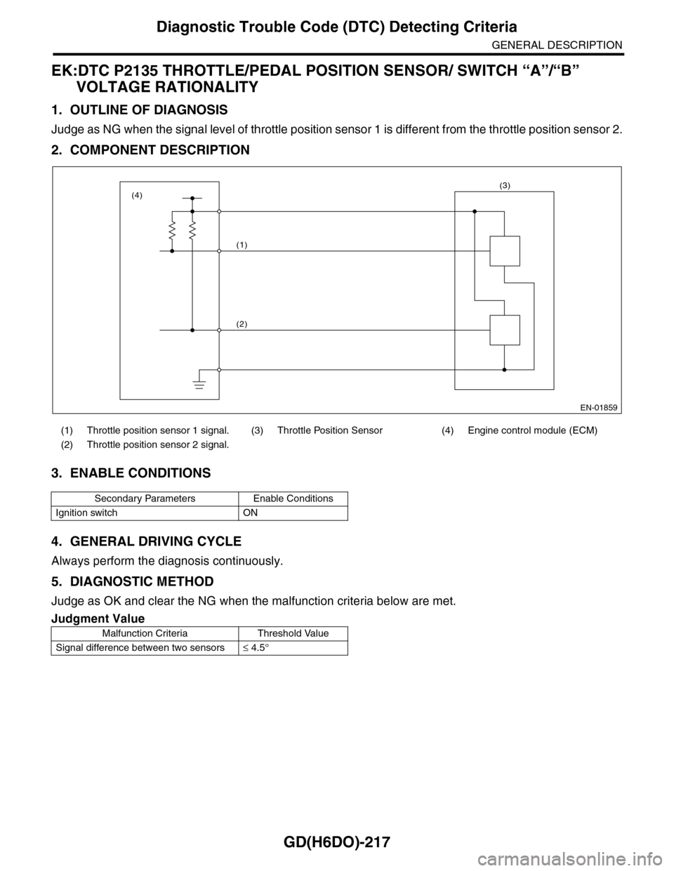
Judge as NG when the signal level of throttle position sensor 1 is different from the throttle position sensor 2.
2. COMPONENT DESCRIPTION
3. ENABLE CONDITIONS
4. GENERAL DRIVING CYCLE
Always perform the diagnosis continuously.
5. DIAGNOSTIC METHOD
Judge as OK and clear the NG when the malfunction criteria below are met.
(1) Throttle position sensor 1 signal. (3) Throttle Position Sensor (4) Engine control module (ECM)
(2) Throttle position sensor 2 signal.
Secondary Parameters Enable Conditions
Ignition switch ON
Judgment Value
Malfunction Criteria Threshold Value
Signal difference between two sensors≤ 4.5°
EN-01859
(1)
(2)
(3)(4)
Page 1830 of 2453
GD(H6DO)-218
Diagnostic Trouble Code (DTC) Detecting Criteria
GENERAL DESCRIPTION
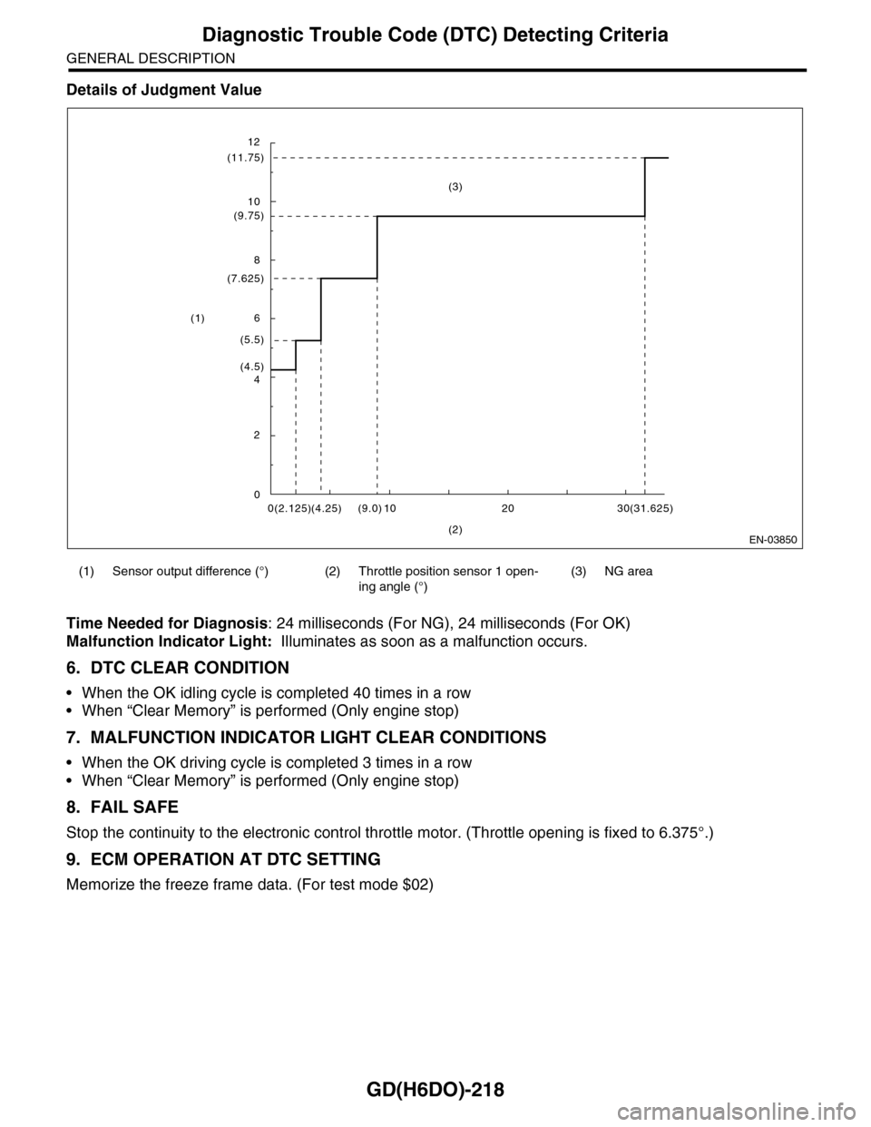
Details of Judgment Value
Time Needed for Diagnosis: 24 milliseconds (For NG), 24 milliseconds (For OK)
Malfunction Indicator Light: Illuminates as soon as a malfunction occurs.
6. DTC CLEAR CONDITION
•When the OK idling cycle is completed 40 times in a row
•When “Clear Memory” is performed (Only engine stop)
7. MALFUNCTION INDICATOR LIGHT CLEAR CONDITIONS
•When the OK driving cycle is completed 3 times in a row
•When “Clear Memory” is performed (Only engine stop)
8. FAIL SAFE
Stop the continuity to the electronic control throttle motor. (Throttle opening is fixed to 6.375°.)
9. ECM OPERATION AT DTC SETTING
Memorize the freeze frame data. (For test mode $02)
(1) Sensor output difference (°) (2) Throttle position sensor 1 open-
ing angle (°)
(3) NG area
EN-03850
12
(11.75)
10
(9.75)
8
(7.625)
6
(5.5)
(4.5)4
2
00(2.125)(4.25) 10(9.0) 20 30(31.625)
(2)
(1)
(3)
Page 1831 of 2453
GD(H6DO)-219
Diagnostic Trouble Code (DTC) Detecting Criteria
GENERAL DESCRIPTION
EL:DTC P2138 THROTTLE/PEDAL POSITION SENSOR/ SWITCH “D”/“E” VOLT-
AGE RATIONALITY
1. OUTLINE OF DIAGNOSIS
Judge as NG when the signal level of throttle position sensor 1 is different from the throttle position sensor 2.
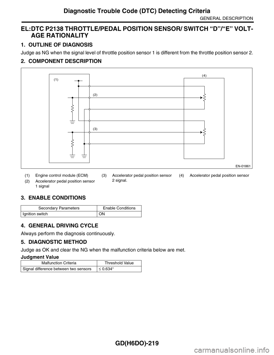
2. COMPONENT DESCRIPTION
3. ENABLE CONDITIONS
4. GENERAL DRIVING CYCLE
Always perform the diagnosis continuously.
5. DIAGNOSTIC METHOD
Judge as OK and clear the NG when the malfunction criteria below are met.
(1) Engine control module (ECM) (3)
Accelerator pedal position sensor
2 signal.
(4) Accelerator pedal position sensor
(2) Accelerator pedal position sensor
1 signal
Secondary Parameters Enable Conditions
Ignition switch ON
Judgment Value
Malfunction Criteria Threshold Value
Signal difference between two sensors≤ 0.634°
EN-01861
(2)
(3)
(4)(1)
Page 1832 of 2453

GD(H6DO)-220
Diagnostic Trouble Code (DTC) Detecting Criteria
GENERAL DESCRIPTION
Details of Judgment Value
Time Needed for Diagnosis:
•116 milliseconds (For NG)
•1000 milliseconds (For OK)
Malfunction Indicator Light: Illuminates as soon as a malfunction occurs.
6. DTC CLEAR CONDITION
•When the OK idling cycle is completed 40 times in a row
•When “Clear Memory” is performed
7. MALFUNCTION INDICATOR LIGHT CLEAR CONDITIONS
•When the OK driving cycle is completed 3 times in a row
•When “Clear Memory” is performed
8. FAIL SAFE
Throttle opening is fixed to 6.375°.
9. ECM OPERATION AT DTC SETTING
Memorize the freeze frame data. (For test mode $02)
(1) Sensor output difference (°) (2) Throttle position sensor 2 open-
ing angle (°)
(3) NG area
EN-03851
0
(0.916)
(0.634)
(1.297)
(1)
(3)
0(0.6)
(2)
(1.2)(4.0)(2.0)
(2.492)
(1.947)