sensor SUBARU TRIBECA 2009 1.G Service Workshop Manual
[x] Cancel search | Manufacturer: SUBARU, Model Year: 2009, Model line: TRIBECA, Model: SUBARU TRIBECA 2009 1.GPages: 2453, PDF Size: 46.32 MB
Page 1880 of 2453
ME(H6DO)-14
General Description
MECHANICAL
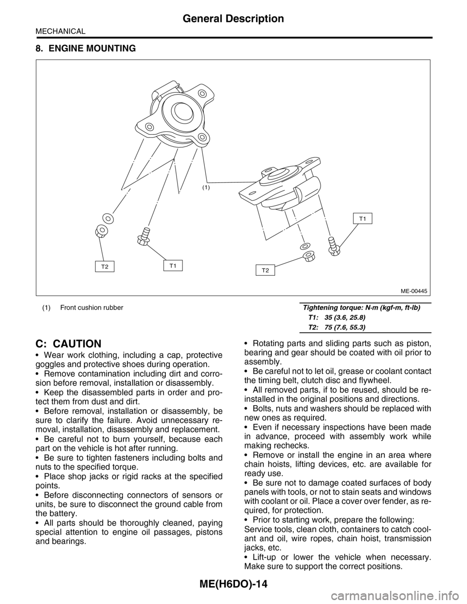
8. ENGINE MOUNTING
C: CAUTION
•Wear work clothing, including a cap, protective
goggles and protective shoes during operation.
•Remove contamination including dirt and corro-
sion before removal, installation or disassembly.
•Keep the disassembled parts in order and pro-
tect them from dust and dirt.
•Before removal, installation or disassembly, be
sure to clarify the failure. Avoid unnecessary re-
moval, installation, disassembly and replacement.
•Be careful not to burn yourself, because each
part on the vehicle is hot after running.
•Be sure to tighten fasteners including bolts and
nuts to the specified torque.
•Place shop jacks or rigid racks at the specified
points.
•Before disconnecting connectors of sensors or
units, be sure to disconnect the ground cable from
the battery.
•All parts should be thoroughly cleaned, paying
special attention to engine oil passages, pistons
and bearings.
•Rotating parts and sliding parts such as piston,
bearing and gear should be coated with oil prior to
assembly.
•Be careful not to let oil, grease or coolant contact
the timing belt, clutch disc and flywheel.
•All removed parts, if to be reused, should be re-
installed in the original positions and directions.
•Bolts, nuts and washers should be replaced with
new ones as required.
•Even if necessary inspections have been made
in advance, proceed with assembly work while
making rechecks.
•Remove or install the engine in an area where
chain hoists, lifting devices, etc. are available for
ready use.
•Be sure not to damage coated surfaces of body
panels with tools, or not to stain seats and windows
with coolant or oil. Place a cover over fender, as re-
quired, for protection.
•Prior to starting work, prepare the following:
Service tools, clean cloth, containers to catch cool-
ant and oil, wire ropes, chain hoist, transmission
jacks, etc.
•Lift-up or lower the vehicle when necessary.
Make sure to support the correct positions.
(1) Front cushion rubber Tightening torque: N·m (kgf-m, ft-lb)
T1: 35 (3.6, 25.8)
T2: 75 (7.6, 55.3)
(1)
T2
T1
T1T2
ME-00445
Page 1906 of 2453
ME(H6DO)-40
Preparation for Overhaul
MECHANICAL
12.Preparation for Overhaul
A: REMOVAL
1) Remove the engine assembly from the body.
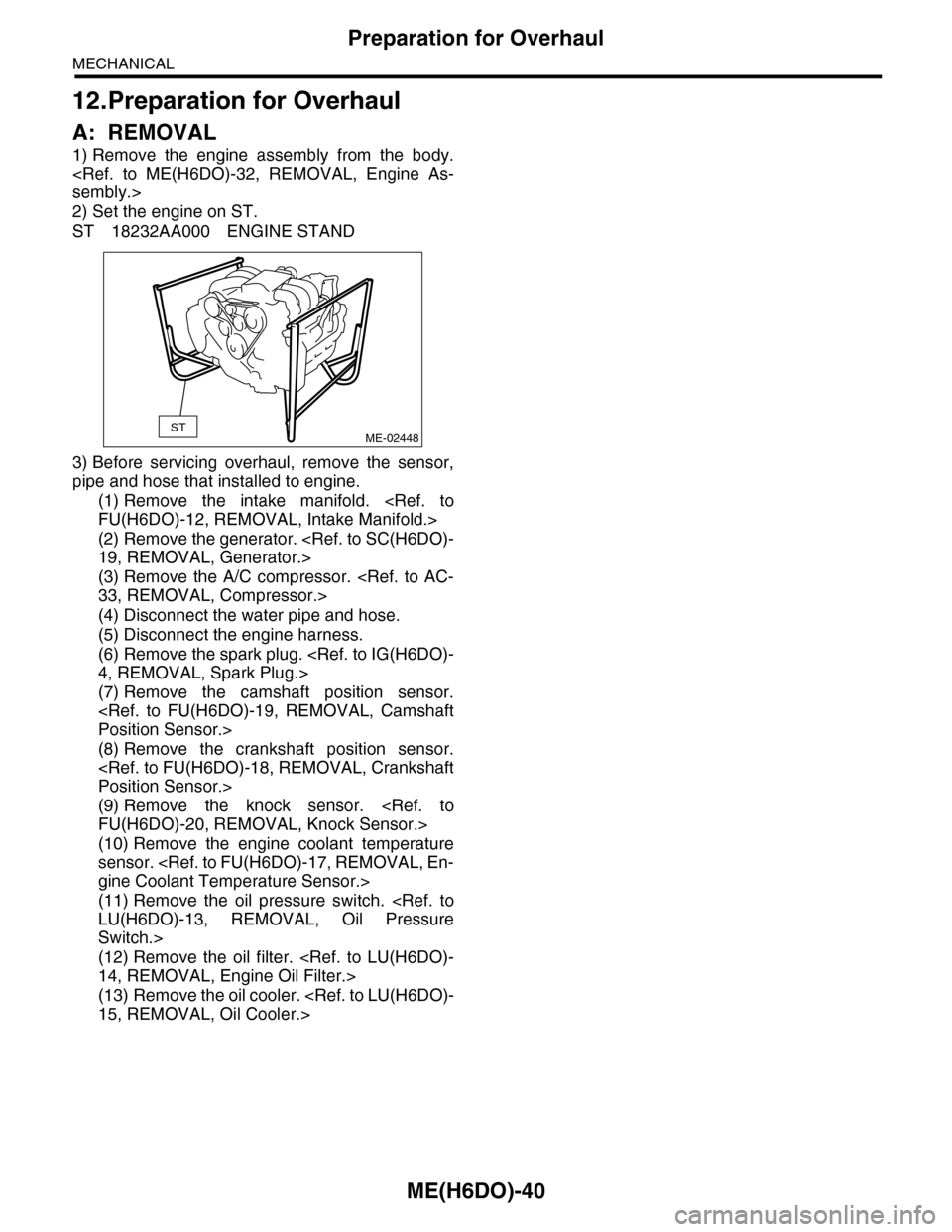
2) Set the engine on ST.
ST 18232AA000 ENGINE STAND
3) Before servicing overhaul, remove the sensor,
pipe and hose that installed to engine.
(1) Remove the intake manifold.
(2) Remove the generator.
(3) Remove the A/C compressor.
(4) Disconnect the water pipe and hose.
(5) Disconnect the engine harness.
(6) Remove the spark plug.
(7) Remove the camshaft position sensor.
(8) Remove the crankshaft position sensor.
(9) Remove the knock sensor.
(10) Remove the engine coolant temperature
sensor.
(11) Remove the oil pressure switch.
Switch.>
(12) Remove the oil filter.
(13) Remove the oil cooler.
STME-02448
Page 1928 of 2453

ME(H6DO)-62
Cylinder Block
MECHANICAL
21.Cylinder Block
A: REMOVAL
NOTE:
Before conducting this procedure, drain the engine
oil completely.
1) Remove the crank pulley.
2) Remove the front chain cover.
3) Remove the timing chain assembly.
4) Remove the cam sprocket.
5) Remove the crank sprocket.
6) Remove the rear chain cover.
7) Remove the camshaft.
8) Remove the cylinder head.
9) Remove the drive plate.
Using the ST, lock the crankshaft.
ST 498497100 CRANKSHAFT STOPPER
10) Remove the crankshaft position sensor plate.
11) Remove the crankshaft position sensor brack-
et.
12) Rotate the engine to set oil pan upper.
13) Remove the bolts which secure oil pan lower to
oil pan upper.
14) Insert an oil pan cutter blade between cylinder
block-to-oil pan clearance and remove the oil pan.
CAUTION:
Do not use a screwdriver or similar tools in
place of oil pan cutter.
15) Remove the oil strainer.
ME-02664
ST
ME-00558
ME-00559
ME-00560
LU-02108
Page 1933 of 2453
ME(H6DO)-67
Cylinder Block
MECHANICAL
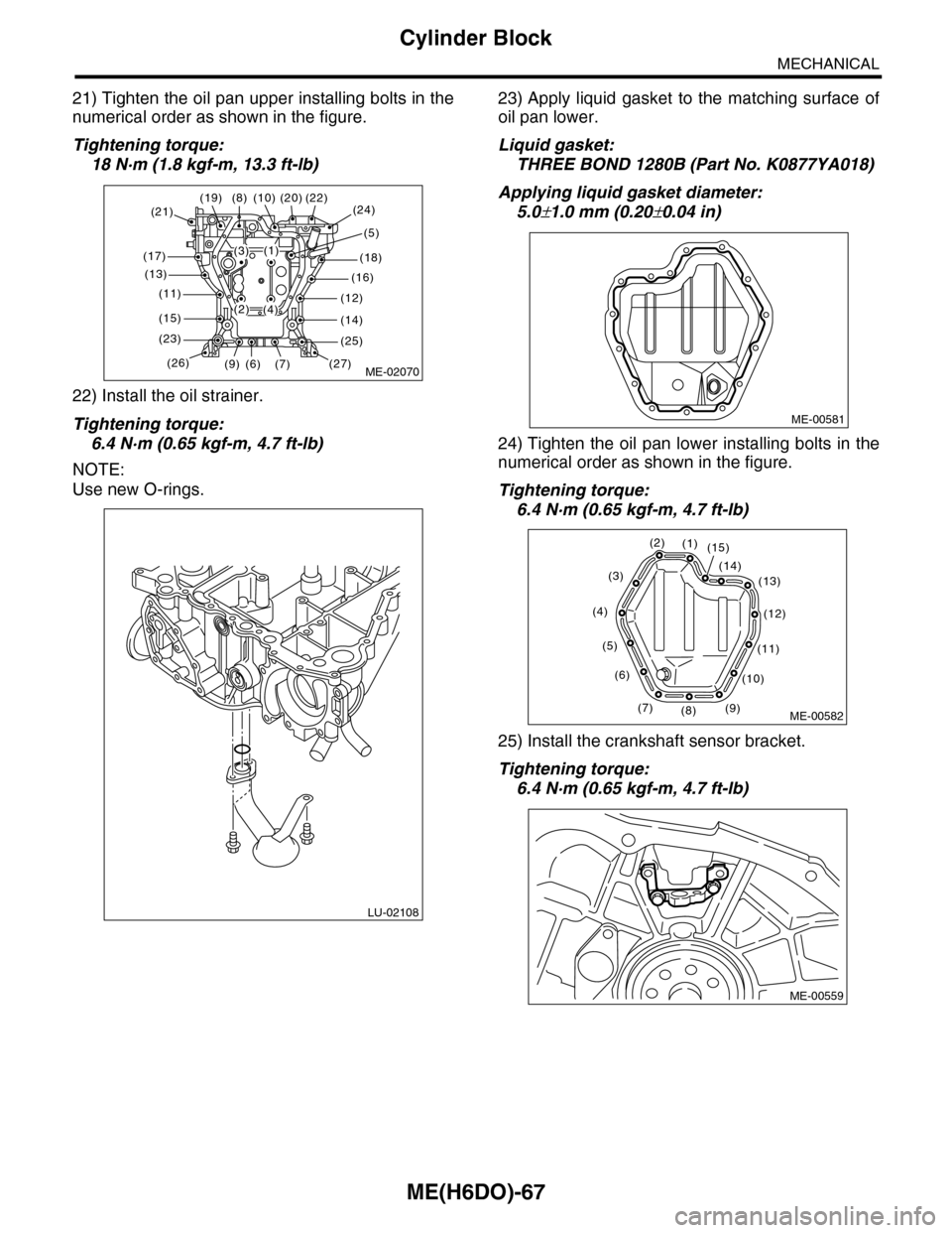
21) Tighten the oil pan upper installing bolts in the
numerical order as shown in the figure.
Tightening torque:
18 N·m (1.8 kgf-m, 13.3 ft-lb)
22) Install the oil strainer.
Tightening torque:
6.4 N·m (0.65 kgf-m, 4.7 ft-lb)
NOTE:
Use new O-rings.
23) Apply liquid gasket to the matching surface of
oil pan lower.
Liquid gasket:
THREE BOND 1280B (Part No. K0877YA018)
Applying liquid gasket diameter:
5.0±1.0 mm (0.20±0.04 in)
24) Tighten the oil pan lower installing bolts in the
numerical order as shown in the figure.
Tightening torque:
6.4 N·m (0.65 kgf-m, 4.7 ft-lb)
25) Install the crankshaft sensor bracket.
Tightening torque:
6.4 N·m (0.65 kgf-m, 4.7 ft-lb)
ME-02070
(19)
(14)
(12)
(16)
(24)(22)
(27)
(25)
(21)
(17)
(13)
(11)
(15)
(23)
(26)
(20)
(18)
(7)(6)(9)
(8) (10)
(5)
(3)
(4)
(1)
(2)
LU-02108
ME-00581
(1)(2)
(3)
(4)
(5)
(6)
(7)(8)(9)
(10)
(11)
(12)
(13)(14)
(15)
ME-00582
ME-00559
Page 1934 of 2453
ME(H6DO)-68
Cylinder Block
MECHANICAL
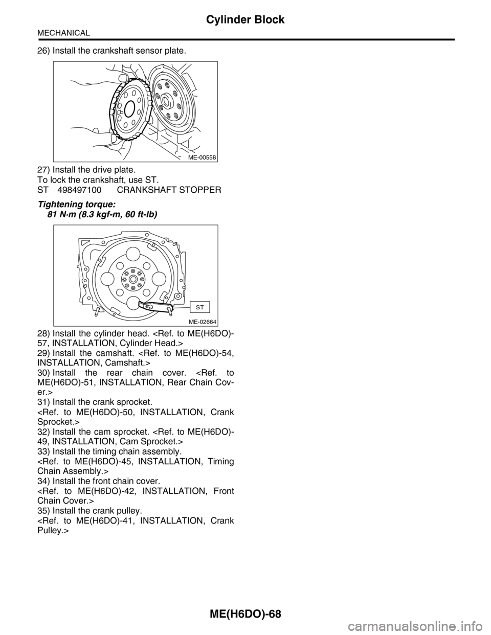
26) Install the crankshaft sensor plate.
27) Install the drive plate.
To lock the crankshaft, use ST.
ST 498497100 CRANKSHAFT STOPPER
Tightening torque:
81 N·m (8.3 kgf-m, 60 ft-lb)
28) Install the cylinder head.
29) Install the camshaft.
30) Install the rear chain cover.
er.>
31) Install the crank sprocket.
32) Install the cam sprocket.
33) Install the timing chain assembly.
34) Install the front chain cover.
35) Install the crank pulley.
ME-00558
ME-02664
ST
Page 1944 of 2453
ME(H6DO)-78
Oil Switching Solenoid Valve
MECHANICAL
23.Oil Switching Solenoid Valve
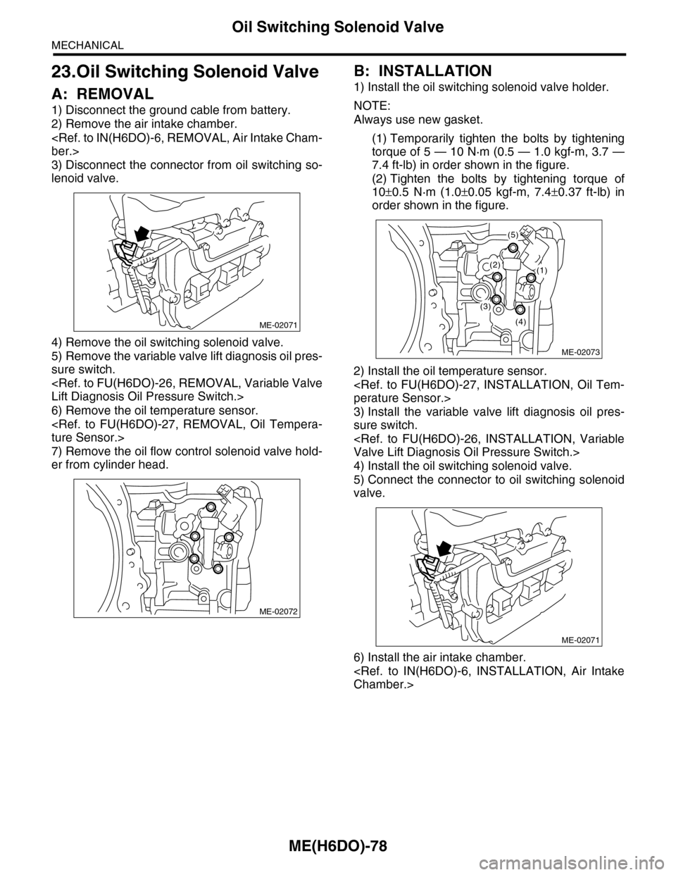
A: REMOVAL
1) Disconnect the ground cable from battery.
2) Remove the air intake chamber.
3) Disconnect the connector from oil switching so-
lenoid valve.
4) Remove the oil switching solenoid valve.
5) Remove the variable valve lift diagnosis oil pres-
sure switch.
6) Remove the oil temperature sensor.
7) Remove the oil flow control solenoid valve hold-
er from cylinder head.
B: INSTALLATION
1) Install the oil switching solenoid valve holder.
NOTE:
Always use new gasket.
(1) Temporarily tighten the bolts by tightening
torque of 5 — 10 N·m (0.5 — 1.0 kgf-m, 3.7 —
7.4 ft-lb) in order shown in the figure.
(2) Tighten the bolts by tightening torque of
10±0.5 N·m (1.0±0.05 kgf-m, 7.4±0.37 ft-lb) in
order shown in the figure.
2) Install the oil temperature sensor.
3) Install the variable valve lift diagnosis oil pres-
sure switch.
4) Install the oil switching solenoid valve.
5) Connect the connector to oil switching solenoid
valve.
6) Install the air intake chamber.
ME-02071
ME-02072
ME-02073
(2)(1)
(5)
(4)
(3)
ME-02071
Page 1957 of 2453
SP(H6DO)-2
General Description
SPEED CONTROL SYSTEMS
1. General Description
A: SPECIFICATION
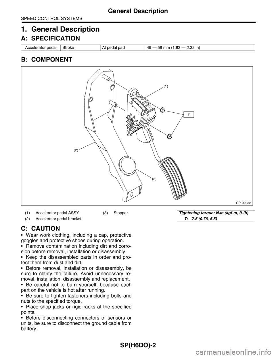
B: COMPONENT
C: CAUTION
•Wear work clothing, including a cap, protective
goggles and protective shoes during operation.
•Remove contamination including dirt and corro-
sion before removal, installation or disassembly.
•Keep the disassembled parts in order and pro-
tect them from dust and dirt.
•Before removal, installation or disassembly, be
sure to clarify the failure. Avoid unnecessary re-
moval, installation, disassembly and replacement.
•Be careful not to burn yourself, because each
part on the vehicle is hot after running.
•Be sure to tighten fasteners including bolts and
nuts to the specified torque.
•Place shop jacks or rigid racks at the specified
points.
•Before disconnecting connectors of sensors or
units, be sure to disconnect the ground cable from
battery.
Accelerator pedal Stroke At pedal pad 49 — 59 mm (1.93 — 2.32 in)
(1) Accelerator pedal ASSY (3) StopperTightening torque: N·m (kgf-m, ft-lb)
(2) Accelerator pedal bracket T: 7.5 (0.76, 5.5)
SP-02032
(1)
(2)
(3)
T
Page 1963 of 2453
SC(H6DO)-5
General Description
STARTING/CHARGING SYSTEMS
C: CAUTION
•Wear work clothing, including a cap, protective
goggles and protective shoes during operation.
•Remove contamination including dirt and corro-
sion before removal, installation or disassembly.
•Keep the disassembled parts in order and pro-
tect them from dust and dirt.
•Before removal, installation or disassembly, be
sure to clarify the failure. Avoid unnecessary re-
moval, installation, disassembly and replacement.
•Be careful not to burn yourself, because each
part on the vehicle is hot after running.
•Be sure to tighten fasteners including bolts and
nuts to the specified torque.
•Place shop jacks or rigid racks at the specified
points.
•Before disconnecting connectors of sensors or
units, be sure to disconnect the ground cable from
battery.
Page 2020 of 2453
5AT-4
General Description
AUTOMATIC TRANSMISSION
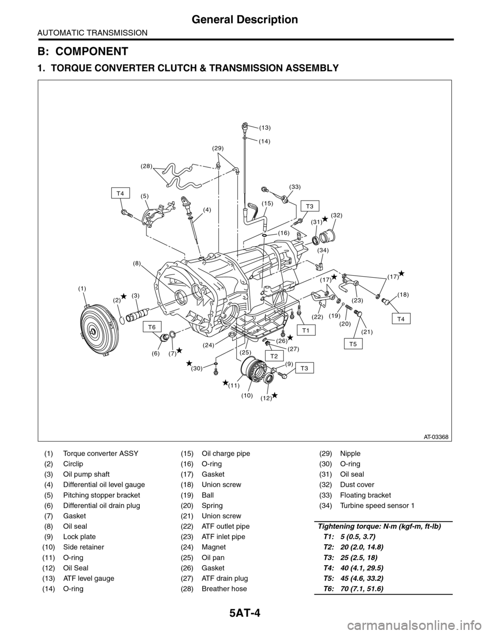
B: COMPONENT
1. TORQUE CONVERTER CLUTCH & TRANSMISSION ASSEMBLY
(1) Torque converter ASSY (15) Oil charge pipe (29) Nipple
(2) Circlip (16) O-ring (30) O-ring
(3) Oil pump shaft (17) Gasket (31) Oil seal
(4) Differential oil level gauge (18) Union screw (32) Dust cover
(5) Pitching stopper bracket (19) Ball (33) Floating bracket
(6) Differential oil drain plug (20) Spring (34) Turbine speed sensor 1
(7) Gasket (21) Union screw
(8) Oil seal (22) ATF outlet pipeTightening torque: N·m (kgf-m, ft-lb)
(9) Lock plate (23) ATF inlet pipeT1: 5 (0.5, 3.7)
(10) Side retainer (24) MagnetT2: 20 (2.0, 14.8)
(11) O-ring (25) Oil panT3: 25 (2.5, 18)
(12) Oil Seal (26) GasketT4: 40 (4.1, 29.5)
(13) ATF level gauge (27) ATF drain plugT5: 45 (4.6, 33.2)
(14) O-ring (28) Breather hoseT6: 70 (7.1, 51.6)
T6
T4
T3
T5
T1
T2
T4
T3
(12)
(11)
(7)(6)
(10)
(21)
(20)
(23)
(26)
(25)(24)(27)
(30)
(19)(22)
(18)
(17)
(34)
(32)
(16)
(15)
(14)
(13)
(28)
(4)
(5)
(1)
(2)(3)
(8)
(29)
(33)
(31)
(9)
(17)
AT-03368
Page 2025 of 2453
5AT-9
General Description
AUTOMATIC TRANSMISSION
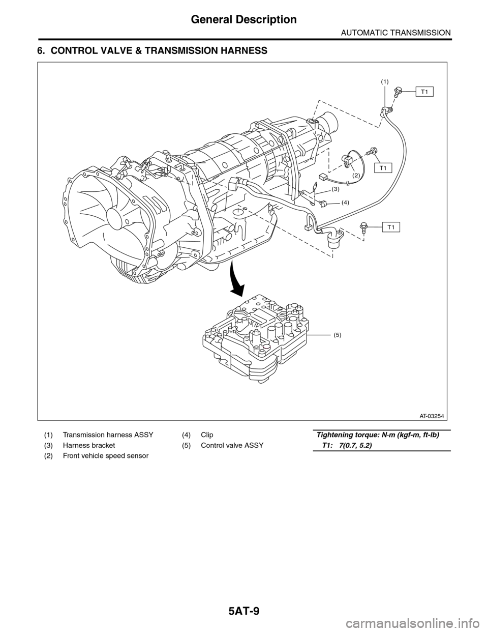
6. CONTROL VALVE & TRANSMISSION HARNESS
(1) Transmission harness ASSY (4) ClipTightening torque: N·m (kgf-m, ft-lb)
(3) Harness bracket (5) Control valve ASSYT1: 7(0.7, 5.2)
(2) Front vehicle speed sensor
(1)
(2)
(3)
(4)
(5)
T1
T1
T1
AT-03254